EP0304584A1 - Kreiselmäher - Google Patents
Kreiselmäher Download PDFInfo
- Publication number
- EP0304584A1 EP0304584A1 EP88110204A EP88110204A EP0304584A1 EP 0304584 A1 EP0304584 A1 EP 0304584A1 EP 88110204 A EP88110204 A EP 88110204A EP 88110204 A EP88110204 A EP 88110204A EP 0304584 A1 EP0304584 A1 EP 0304584A1
- Authority
- EP
- European Patent Office
- Prior art keywords
- bearing
- mower according
- cylinder
- bearing cylinder
- bore
- Prior art date
- Legal status (The legal status is an assumption and is not a legal conclusion. Google has not performed a legal analysis and makes no representation as to the accuracy of the status listed.)
- Ceased
Links
- 230000005540 biological transmission Effects 0.000 claims description 25
- 238000005520 cutting process Methods 0.000 claims description 23
- 238000007789 sealing Methods 0.000 claims description 13
- 238000005096 rolling process Methods 0.000 claims description 10
- 239000000314 lubricant Substances 0.000 claims description 9
- 210000000056 organ Anatomy 0.000 claims description 3
- 125000006850 spacer group Chemical group 0.000 description 14
- 230000001681 protective effect Effects 0.000 description 8
- 238000004804 winding Methods 0.000 description 5
- 239000000463 material Substances 0.000 description 4
- 230000007246 mechanism Effects 0.000 description 4
- 239000004459 forage Substances 0.000 description 3
- 238000003754 machining Methods 0.000 description 3
- 230000000295 complement effect Effects 0.000 description 2
- 230000000694 effects Effects 0.000 description 2
- 238000000034 method Methods 0.000 description 2
- 230000008439 repair process Effects 0.000 description 2
- 239000002689 soil Substances 0.000 description 2
- 229910001018 Cast iron Inorganic materials 0.000 description 1
- 239000000853 adhesive Substances 0.000 description 1
- 230000001070 adhesive effect Effects 0.000 description 1
- 238000000429 assembly Methods 0.000 description 1
- 238000005452 bending Methods 0.000 description 1
- 230000015572 biosynthetic process Effects 0.000 description 1
- 230000000903 blocking effect Effects 0.000 description 1
- 238000010276 construction Methods 0.000 description 1
- 230000002950 deficient Effects 0.000 description 1
- 238000006073 displacement reaction Methods 0.000 description 1
- 238000003306 harvesting Methods 0.000 description 1
- 238000005461 lubrication Methods 0.000 description 1
- 238000004519 manufacturing process Methods 0.000 description 1
- 238000012986 modification Methods 0.000 description 1
- 230000004048 modification Effects 0.000 description 1
- 238000000465 moulding Methods 0.000 description 1
- 230000008569 process Effects 0.000 description 1
- 230000035939 shock Effects 0.000 description 1
- 238000003466 welding Methods 0.000 description 1
Images


Classifications
-
- A—HUMAN NECESSITIES
- A01—AGRICULTURE; FORESTRY; ANIMAL HUSBANDRY; HUNTING; TRAPPING; FISHING
- A01D—HARVESTING; MOWING
- A01D34/00—Mowers; Mowing apparatus of harvesters
- A01D34/01—Mowers; Mowing apparatus of harvesters characterised by features relating to the type of cutting apparatus
- A01D34/412—Mowers; Mowing apparatus of harvesters characterised by features relating to the type of cutting apparatus having rotating cutters
- A01D34/63—Mowers; Mowing apparatus of harvesters characterised by features relating to the type of cutting apparatus having rotating cutters having cutters rotating about a vertical axis
- A01D34/64—Mowers; Mowing apparatus of harvesters characterised by features relating to the type of cutting apparatus having rotating cutters having cutters rotating about a vertical axis mounted on a vehicle, e.g. a tractor, or drawn by an animal or a vehicle
- A01D34/66—Mowers; Mowing apparatus of harvesters characterised by features relating to the type of cutting apparatus having rotating cutters having cutters rotating about a vertical axis mounted on a vehicle, e.g. a tractor, or drawn by an animal or a vehicle with two or more cutters
- A01D34/664—Disc cutter bars
Definitions
- the present invention relates to a mower comprising rotary cutting members provided with at least one cutting tool, at least one of said rotary cutting members being driven by transmission means housed in a casing situated under said rotary cutting members, said transmission means comprising a wheel integral with the shaft of the rotary cutting member driven from below which is guided in rotation in a bearing housed in the bore of a bearing cylinder forming an integral part of the casing.
- Such a mower has certain advantages, in that, in order to link the bearing cylinder to the housing, there is no need to carry out complex machining on the bearing cylinder and the housing, nor to provide for components 'complex assembly.
- Such a connection can in fact be made directly by molding, for example when the casing comprises cast iron elements, or be made by a welding process.
- the object of the present invention is, therefore, to modify the known mowers so that their mounting can be done economically and that subsequent interventions can be carried out very quickly and without incurring significant costs.
- the mower according to the invention is characterized in that the smallest diameter of the bore of the bearing cylinder is greater than the outside diameter of the wheel fixed on the shaft, so that the assembly pre-assembled shaft - wheel - bearing can be mounted in the bore of the bearing cylinder and disassembled from said bore.
- the mounting of the mower according to the invention can be done very easily. economic.
- the shaft - wheel - bearing assembly which represents a small unit, can be pre-assembled before final assembly. As this assembly is compact, this pre-assembly can even be automated.
- the bearing which guides the shaft of the corresponding rotary cutting member in rotation comprises a rolling box and at least one bearing.
- the bearing or bearings are mounted in the bearing box in a non-removable manner.
- the assembly comprises means which allow a substantially continuous adjustment of the operating clearance of the transmission means such as pairs of toothed wheels for example.
- the means which allow this adjustment consist of at least one member which is deformed during mounting of the bearing in the bearing cylinder.
- the bearing which has on its external surface at least a part which is threaded, and which collaborates with a threaded part of the bore of the bearing cylinder.
- This latter embodiment makes it possible to have a large range of adjustment. The adjustment is all the more fine as the thread pitch is fine.
- the outer surface of the bearing comprises an unthreaded part which centers in an unthreaded part of the bearing cylinder. This arrangement makes it possible to have good centering of the shaft of the rotary cutting member in the bearing cylinder.
- the non-threaded parts of the bearing and of the bearing cylinder cooperate before the threaded parts of said bearing and of said bearing cylinder begin to be engaged.
- This arrangement allows the bearing to be easily screwed into the bearing cylinder. Indeed, as the bearing is already centered in the bearing cylinder before screwing, any trial and error, to bring the threaded part of the bearing and that of the bearing cylinder opposite one another so that the screwing can actually be undertaken, is eliminated.
- the threaded parts of the bearing and of the bearing cylinder are arranged in such a way that they cannot be brought into engagement with one another when, during assembly, the transmission means such as the pair of toothed wheels for example, are not in engagement.
- This characteristic is very advantageous in terms of mounting. Indeed, it allows the use of screwing machines without risking blocking the bearing in the bearing cylinder while the transmission means are not engaged. This characteristic therefore reduces the risks of assembly and correlatively also the assembly costs.
- these members are brought into collaboration by deformation of one and / or the other.
- This arrangement thus makes it possible to precisely maintain the operating clearance of the transmission means without causing high mounting costs.
- the bearing is provided with gripping means which allow its screwing and unscrewing.
- these means are constituted by at least one recess arranged in the upper face of the bearing. It is thus possible to be able to disassemble the bearing with a striking tool such as a hammer, without risking breaking said gripping means.
- the gripping means are constituted by a central part which emerges at the upper face of the bearing and which has a non-circular and preferably polygonal outer surface.
- sealing means prevent leakage of lubricant between the bearing and the bearing cylinder.
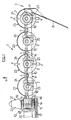
- FIG. 1 there is shown a mower or more precisely the cutter bar (1) of a mower.
- This cutter bar (1) comprises four discs (2,3) each rotating around an axis directed upwards.
- Each disc (2, 3) is provided with two cutting tools (4) which are mounted diametrically opposite on the outer edge of the disc.
- the cutting tools (4) are mounted on the discs (2, 3) so that said cutting tools (4) extend outwards under the effect of centrifugal force, and qu '' they can pivot backwards when they encounter an obstacle during their rotation.
- the disc (3) located at the right end (5) of the cutter bar (1), seen in the working direction defined by the arrow (6), is surmounted by a cap (7).
- This cover (7) collaborates with a device for reducing the swath of cut fodder such as the swath board (8) for example, so that the cut swath of fodder is separated from the forage still standing.
- the discs (2, 3) are guided in rotation in a casing (9) disposed under said discs.
- This casing (9), as will be explained below in more detail, is formed by a succession of modules (10).
- the casing (9) is provided with an end module (11) which extends substantially up to the external trajectory described by the disc ( 3), or slightly beyond said trajectory.
- the casing (9) is provided with a return casing (13).
- transmission means such as a transmission shaft (14) which collaborates with toothed wheels for example, with a view to rotating the discs (2, 3).
- the rotary drive of these transmission means is achieved by means of a drive mechanism housed in the gearbox (13) and which will be described later in more detail.
- This drive mechanism receives the movement of a pulley (15) wedged on the axis (16).
- the pulley (15) is rotated by means of another pulley not shown by means of belts (17).
- This other pulley is, in a manner known to those skilled in the art, driven by the power take-off of a tractor, not shown, to which the mower is coupled, by means of a universal joint shaft, not shown. .
- the gearbox (13) has two cylindrical surfaces (18) substantially concentric with the axis (16) of the input of said gearbox (13). These cylindrical bearings (18) support a yoke (19) fixed to a frame (20) by means of which the mower is coupled to the tractor. With this arrangement, the cutter bar (1) can follow the unevenness of the ground by pivoting around the axis of the cylindrical bearings (18) without the various drive members being subjected to additional stresses. Furthermore, it is possible to pivot the cutter bar (1) to a sensitive position vertical to reduce the width of the mower during transport.
- a shoe (21) which has a front part (22) raised like the front of 'a ski. This shoe (21) allows the mower to slide on the ground and avoid catching cut forage on the gearbox (13).
- disc protective pads At the front, under each disc (2, 3), the casing (9) is provided with disc protective pads (23). These disc protective pads have a front portion (24) having a top circular shape whose radius is larger than the radius of the extreme trajectory of the discs (2, 3) but smaller than the radius of the trajectory end of the cutting tools (4). Furthermore, said disc protective pads (23) have a back portion (25) in the form of a pad, on which also rests the cutter bar (1).
- the casing (9) comprises a plurality of modules (10).
- Each module (10) supports a disc (2, 3).
- the module (10) consists of a housing (26) in which said disc (2, 3) is guided in rotation, and a spacer (27) which extends between this housing (26) and the housing ( 26) of an adjacent module (10).
- the spacer (27) of a module (10) extends to the left of the housing (26) of the same module, seen in the direction of advance of the machine at work.
- the different modules (10) are centered relative to each other by means of a centering ring (28) which extends both inside the spacer (27) of a module (10) and inside the housing (26) of the adjacent module (10).
- the centering ring (28) has a length such that it can absorb part of the bending forces exerted on the cutter bar (1) during tra vail and during transport.
- the different modules (10) are linked to each other by means of assembly members (29). To do this, each module (10) has at each of its ends a flange (30).
- the flanges (30) of two adjacent modules (10) are linked together by the assembly members (29) which are constituted, in the embodiment described, by screws (31) whose rod (32) passes through the two adjacent flanges (30), and by nuts (33) screwed onto said rods (32).
- the flanges (30) each have a certain width so that the length of the screws (31) is sufficient to allow them to withstand the stresses to which they are subjected.
- the casing (9) thus formed contains a transmission shaft (14).
- the transmission shaft (14) collaborates with a pair of bevel gearwheels (34, 35) in order to transmit the movement to the corresponding disc (2, 3).
- the drive shaft (14) passes through the bore (36) of the toothed wheel (34) which has the shape complementary to that of the drive shaft (14).
- the drive shaft (14) has a hexagonal section (see Figure 4). It is however possible that the shaft has a section of another shape as soon as this shape allows a rotation drive. Similarly, it is possible that the drive shaft (14) has the shape allowing the rotational drive only in the area where it collaborates with the toothed wheel (34).
- the toothed wheel (34) is integral with a sleeve (37) which also surrounds the transmission shaft (14).
- the gear wheel (34) - sleeve (37) assembly is guided in rotation in the housing (26) by means of two bearings such as ball bearings (38, 39).
- the toothed wheel (34) has a cylindrical surface (40) on which is mounted the bearing (38) which abuts against a shoulder (41) of the toothed wheel (34).
- the sleeve (37) meanwhile, has at its end remote from the toothed wheel (34), also a cylindrical surface (42) on which is mounted the bearing (39) which abuts against a shoulder (43) of the sleeve ( 37).
- the bearings (38, 39) are thus mounted on the toothed wheel (34) - sleeve (37) assembly so that the teeth of the toothed wheel (34) are located between the two bearings (38, 39).
- the outer diameter of the bearings (38, 39) is the same, which has advantages in the production of the outer surfaces (44, 45) machined in the housing (26). Likewise, the length of said outer surfaces is reduced to a minimum to reduce machining times and facilitate assembly.
- the part (46) of the housing (26) located between the outer surfaces (44, 45) has a larger diameter than the diameter of the surfaces (44, 45).
- Maintaining in translation of the toothed wheel assembly (34) -forge (37) in the housing (26) is produced on the one hand by a shoulder (47) arranged in the housing (26), and on the other hand by a stop member such as a circlip (48). Between the bearing (39) and the stop member (48), thickness washers (49) have been arranged which allow the mounting to reduce or eliminate the axial play resulting from the different dimensional tolerances.
- sealing members such as the sealing rings (50, 40) have been arranged on the cylindrical surfaces (40, 42) of the toothed wheel (34) of the sleeve (37) respectively. 51) which act between the housing (26) and the toothed wheel (34) - sheath (37) assembly.
- the two sealing members (50, 51) are arranged so that the two bearings (38, 39) and the toothing of the toothed wheel (34) are located between the two sealing members (50, 51). With this arrangement, the housing (26) therefore remains sealed inde pending the presence of the drive shaft (14).
- the toothed wheel (34) meshes with the toothed wheel (35) which is integral with a disc shaft (52).
- the disc shaft (52) is guided in rotation in a bearing cylinder (53) by means of a bearing (54) which consists, in the embodiment described, of a rolling box (55) and a bearing (56).
- the bearing cylinder (53) is an integral part of the housing (26) and therefore of the module (10).
- the inner bore of the bearing cylinder (53) has a smooth part (57) and a threaded part (58).
- the outer surface of the bearing (54) also includes a smooth part (59) and a threaded part (60).
- the threading of the threaded parts (58, 60) is advantageously a fine pitch thread.
- the bearing (54) is centered in the bearing cylinder (53), and thanks to the threaded parts (58, 60), said bearing (54) is held in translation in said bearing cylinder (53).
- said paleir (54) is provided at its upper part with a thin cylindrical crown (61) which is partially deformed to collaborate with at least one notch (62) arranged in the upper part of the bearing cylinder (53).
- the bearing box (55) supports the bearing (56) which is centered in the bore of said bearing box.
- This bearing is in the example described, a double row bearing of angular contact balls. It is provided with integrated sealing means (63).
- the bearing (56) is held in translation in the bearing box (55) by means of two shoulders (64, 65).
- the shoulder (64) is produced by machining while the shoulder (65) is produced after mounting the bearing (56) in a manner which will be explained later.
- the disc shaft (52) - toothed wheel (35) assembly is centered in the bore of the bearing (56), the inner ring of which abuts against the shoulder (66) of the toothed wheel (35). Near its free end, the disc shaft (52) is provided with splines (67) which collaborate, with a view to the rotational drive of the disc (2, 3) with splines (68) arranged in a driver ( 69) secured to the disc (2, 3). In order to fix the disc (2, 3) on the disc shaft (52), the latter ends with a threaded part (70) which extends outside the driver (69), and on which is screwed a nut (71) after interposition of a washer (72).
- the bearing (56) is blocked between the shoulder (66) and the driver (69).
- the nut (71) is housed in a recess (73) arranged in the upper part of the driver (69).
- the mounting of a housing (26) is carried out as follows. First, the gear wheel (34) - sleeve (37) assembly is premounted, that is to say that the bearing (38) and then the sealing member (50) are mounted on the cylindrical part (40). ), and on the cylindrical part (42) the bearing (39). The assembly thus pre-assembled is then threaded into the housing (26) until the bearing (38) abuts against the shoulder (47). The number of washers of thickness (49) is then put in place and the assembly is locked axially using the stop member (48). The housing (26) is then sealed by mounting the sealing member (51). The gear wheel (35) - disc shaft (52) - bearing (54) is then premounted.
- the bearing (54) is mounted on the disc shaft (52) until it abuts on the shoulder (66). This assembly is then mounted in the bearing cylinder (53). This is possible because the smaller diameter of the bearing cylinder bore (53) is more larger than the outside diameter of the gear wheel (35).
- the bearing (54) first centers in the bearing cylinder (53) via the smooth parts (57, 59) before the threaded parts (58, 60) can be screwed one inside the other. This ensures that the two threaded parts (58, 60) are opposite one another, which makes it possible to avoid trial and error when the screwing begins.
- the threaded parts (58, 60) are arranged in such a way in the housing (26) respectively on the bearing (54), relative to the toothed wheels (34, 35), so that said threaded parts (58, 60 ) cannot be engaged when a tooth of the toothed wheel (35) abuts on a tooth of the toothed wheel (34).
- the screwing can then only be carried out when one of the toothed wheels has been slightly turned relative to the other.
- the bearing (54) is then screwed into the bearing cylinder (53), the toothed wheel (35) is brought closer to the toothed wheel (34).
- the screwing of the bearing (54) is stopped. in the bearing cylinder (53). To maintain this position, a part of the thin cylindrical crown (61) is deformed to make it penetrate into at least one notch (62). It will be noted that to facilitate the subsequent screwing and unscrewing during an intervention, the bearing (54) is provided with at least one gripping means such as the recess (74).
- the bearing (54) Since the bearing (54) is not centered in the bearing cylinder (53) with tightening, and depending on the nature of the lubricant contained in the housing (26), it may prove necessary to prevent said lubricant from leak between said bearing (54) and said bearing cylinder (53). To do this, it is possible to have between these two parts of the sealing means, such as an adhesive deposited for example between the bearing (54) and the bearing cylinder (53).
- the gear (34) extends to the left of the disc shaft (52). This position therefore defines a direction of rotation of the corresponding disc.
- the assembly must therefore be done so that the corresponding toothed wheel (34) extends to the right of the disc axis (52), the drive shaft (14) rotating. always in the same direction.
- the assembly of the toothed wheel (34) - sleeve (37) assembly in the corresponding housing (26) will be carried out as follows.
- the sealing member (50) will be mounted on the cylindrical part (42) and the assembly will be threaded into the casing (26) sleeve (37) first, until the bearing (39) abuts against the shoulder (47).
- the outer surface of the latter has two zones (75 and 76).
- the area (75) is located in the upper part of the outer surface of the bearing cylinder (53) and extends inside a bore (77) made in the driver (69).
- the diameter of the bore (77) is slightly larger than the diameter of the zone (75) in order to form a baffle.
- the zone (76) extends from the zone (75) downwards, and has a smaller diameter than that of the area (75). In addition, the length of the zone (76) is relatively large.
- the lower surface (78) of the driver (69) extends substantially in the vicinity of the border between the zones (75 and 76) and preferably slightly higher than said border.
- the lower surface (78) of the driver (69) can extend from the vicinity of the border between the zones (75 and 76) outwards and upwards.
- An exemplary embodiment of such an arrangement is shown in Figure 5 where the lower surface (78) of the driver (69) is substantially conical. With this arrangement, the risks of winding up strands of fodder or filiform bodies are substantially reduced since the space between the fixed locations where the strands of fodder or filiform bodies could catch on and the rotating disc is relatively large.
- Figure 3 shows a top view of the cutter bar (1).
- the discs (2, 3) have been drawn in phantom.
- the axis (79) of the bearing cylinder (53) which also corresponds to the axis of rotation of the corresponding disc (2, 3) is located closer to the front edge (80) of the housing ( 9) only from the rear edge (81) of this casing.
- the overcut triangle (82) which is defined by the front intersection point (83) of the extreme trajectories (84, 85) described by the cutting tools (4) of two adjacent discs, and the front edge (80) of the casing (9), is very large. This ensures a good cut of the forage between two adjacent discs.
- This disc protective pad (23) comprises, as said above, a front part (24) having a substantially circular shape and substantially centered on the axis (79).
- the disc protective pad (23) is fixed to the casing (9) by means of a number of fixing members (86), three in the example described. These fasteners (86) extend near the front edge (80) and the rear edge (81) of the housing (9).
- the assembly members (29) which link the different modules (10) together also extend at the front and at the rear of the flanges (30).
- the distance (87) between the assembly members (29) which extend at the front, and those which extend at the rear, is relatively large so that the connection between the modules (10) is very resistant.
- Figure 4 shows a cross section of the cutter bar (1).
- the disc protective pads (23) partially fit on the front edge (80) of the housing (9).
- the front edge (80) of the spacer (27) has a relatively pointed shape. Thanks to this shape, the risks of sticking of soil or plant debris to said front edge (80) are reduced, which would reduce the quality of the cut. It should be noted that the spacer (27) has this pointed shape at least in the zone (89) which extends between two neighboring disks (2, 3) where the cutting tools (4) pass over the casing (9) during their rotation (see Figure 3).
- the lower face (90) of the spacer (27) extends at a certain distance (91) from the surface of the ground (92).
- this space between the underside (90) of the spacer (27) and the ground surface (92) preferably extends over the entire length of the spacer (27).
- the front edge (80) of the spacer (27) advantageously has an inclined plane (93) directed backwards and downwards. This inclined plane (93) extends at least in the area (89) of the front edge (80).
- the front edge (80) also has an inclined plane (94) directed upwards and backwards. With this shape, the impact between a cutting tool (4) accidentally bent downwards and the front edge (80) is reduced. In addition, given the speed of rotation, the inclined plane (94) can somewhat straighten a bent cutting tool (4).
- the upper part of the front edge (80) at least has a greater thickness of material than the rest of the cross section of the spacer (27). It should be noted that the inclined plane (94) and the place where the thickness of material is greater extend at least in the zone (89) (see FIG. 3). When a cutting tool (4) folded down has not been able to be fully straightened, it can then strike the rear edge (81) of the adjacent module (10) in the zone (95) above which it passes during of its rotation towards the casing (9).
- the rear edge (81) of the spacer (27) has at least in the area (95), an inclined plane (96) directed forwards and upwards.
- the thickness of material in this area is also greater than in the rest of the cross section of the spacer (27).
- At least one rib (97) which connects the lower face (90) to the upper face (98) of the spacer (27) .
- This rib (97) can even extend into the housing (26) and connect the two flanges (30) of a module (10).
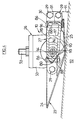
- Figure 5 shows the ends (5) and (12) of the cutter bar (1).
- the cutter bar (1) comprises, as said previously, an end module (11) which closes the end (5) of the cutter bar (1).
- This end module (11) extends to the extreme trajectory of the disc (3) or slightly beyond.
- the end module (11) can protect, to a certain extent, laterally the disc (3).
- the swath board (8) is fixed to the end module (11) using the assembly members (29) which fix said end module (11) to the module (10) which supports the disc. (3), and with the aid of liaison bodies (99).
- the gearbox (13) contains a drive mechanism which transmits the movement of the pulley (15) to the drive shaft (14).
- This drive mechanism consists of the following organs.
- a toothed wheel (100) is wedged on the axis (16) on which the pulley (15) is also wedged.
- This toothed wheel (100) meshes with a toothed wheel (101) which is wedged on an axis (102) which extends substantially perpendicular to the axis (16) and substantially parallel to the drive shaft (14).
- On the axis (102) is also wedged a cylindrical toothed wheel (103) which meshes with another cylindrical toothed wheel (104) wedged on an axis (105).
- the axis (105) extends substantially parallel to the axis (102).
- This cylindrical gear (104) meshes with a third cylindrical gear (106) wedged on the drive shaft (14).
- the axes (102 and 105) are guided in rotation in the gearbox (13) by means of bearings such as bearings known to those skilled in the art.
- the cylindrical toothed wheel (106) has a cylindrical part (107) which extends concentrically on either side of its teeth and which serves as a bearing for bearings such as the bearings (108, 109) guiding said wheel in rotation. toothed (106).
- the gearwheel (106) stops in translation by means of a shoulder (110) arranged in the gearbox (13) and a circlip (111).
- the gearbox (13) also has at its base sealing members (112, 113) which extend between the walls of said gearbox (13) and the cylindrical part (107) in order to make the gearbox waterproof regardless of the presence of the drive shaft (14).
- the cylindrical part (107) has a bore (114) having the shape complementary to that of the transmission shaft (14), in order to cooperate with this transmission shaft (14) which partially extends inside said bore (114).
- the gear wheel (106) - cylindrical part (107) assembly includes a stop member (115) which is rigidly connected to this assembly or at least linked in translation compared to this one.
- a screw (116) is screwed into a threaded hole (117) arranged at the end of the transmission shaft (14 ).
- Figure 6 shows how to form the shoulder (65).
- the tool (120) Before mounting the bore (118) of the rolling box (55) opens onto the face (119) of the rolling box (55) as shown in phantom.
- the tool (120) After mounting the bearing (56) in the bore (118), the tool (120) is pressed into the face (119), which has the effect of deforming the location of the bore (118) which opens onto the face (119).
- the deformation causes a displacement of the material towards the axis of the bearing box (55) which then maintains the bearing (56) in said bearing box (55).
- Figure 7 shows another embodiment of the bearing (54).
- it is a special bearing (56), the outer ring of which is large enough to be centered in the bearing cylinder (53).
- the outer ring of this bearing (56) has a shoulder (121).
- the bore of the bearing cylinder (53) has a shoulder (122).
- an O-ring (123) Between the shoulders (121 and 122) is arranged an O-ring (123).
- the bearing (56) is held axially in the bearing cylinder (53) by means of the shoulders (121 and 122) and the O-ring (123), and by means of a circlip (124) after interposition d 'a washer (125) and thick washers (126).
- the mounting of the bearing (54) in the bearing cylinder (53) and the adjustment of the operating clearance of the toothed wheels (34, 35) are carried out in this case as follows.
- the bearing (54) maintains its position in the bearing cylinder (53). It should be noted that the O-ring (123) also prevents leakage of the lubricant contained in the housing (26), between the bearing (54) and the bearing cylinder (53).
- the O-ring (128) prevents leakage of lubricant between the bearing (54) and the disc shaft (52).
- Figures 8 and 9 show an alternative embodiment of the gripping means which allow the screwing or unscrewing of the bearing (54).
- These means are constituted by a central part (129) which emerges from the upper face of the bearing (54) and which has a non-circular and preferably polygonal external surface. In the example shown, this outer surface is hexagonal. It is thus possible to use a conventional key to screw or unscrew the bearing (54).
- the transmission shaft (14) can be made in several parts. Furthermore, the zones of the transmission shaft (14) where the latter cooperates with a toothed wheel (106, 34) may have a larger nominal dimension than the rest of the transmission shaft (14). In addition, the bearing (54) could also be a plain bearing.
Landscapes
- Life Sciences & Earth Sciences (AREA)
- Environmental Sciences (AREA)
- Harvester Elements (AREA)
- Centrifugal Separators (AREA)
- Iron Core Of Rotating Electric Machines (AREA)
- Supercharger (AREA)
- Input Circuits Of Receivers And Coupling Of Receivers And Audio Equipment (AREA)
Applications Claiming Priority (2)
| Application Number | Priority Date | Filing Date | Title |
|---|---|---|---|
| FR848410916A FR2566992B1 (fr) | 1984-07-06 | 1984-07-06 | Faucheuse rotative. |
| FR8410916 | 1984-07-06 |
Related Parent Applications (1)
| Application Number | Title | Priority Date | Filing Date |
|---|---|---|---|
| EP85440047.0 Division | 1985-07-05 |
Publications (1)
| Publication Number | Publication Date |
|---|---|
| EP0304584A1 true EP0304584A1 (de) | 1989-03-01 |
Family
ID=9305952
Family Applications (2)
| Application Number | Title | Priority Date | Filing Date |
|---|---|---|---|
| EP88110204A Ceased EP0304584A1 (de) | 1984-07-06 | 1985-07-05 | Kreiselmäher |
| EP85440047A Expired - Lifetime EP0171341B1 (de) | 1984-07-06 | 1985-07-05 | Kreiselmäher |
Family Applications After (1)
| Application Number | Title | Priority Date | Filing Date |
|---|---|---|---|
| EP85440047A Expired - Lifetime EP0171341B1 (de) | 1984-07-06 | 1985-07-05 | Kreiselmäher |
Country Status (11)
| Country | Link |
|---|---|
| US (3) | US4720964A (de) |
| EP (2) | EP0304584A1 (de) |
| JP (1) | JPS6135717A (de) |
| AT (1) | ATE51487T1 (de) |
| AU (2) | AU579163B2 (de) |
| DE (1) | DE3576903D1 (de) |
| DK (1) | DK164468C (de) |
| ES (1) | ES8605133A1 (de) |
| FR (1) | FR2566992B1 (de) |
| HU (1) | HU192340B (de) |
| ZA (1) | ZA854808B (de) |
Cited By (2)
| Publication number | Priority date | Publication date | Assignee | Title |
|---|---|---|---|---|
| EP0395180A1 (de) * | 1989-04-28 | 1990-10-31 | C. van der Lely N.V. | Mähmaschine |
| NL1034690C2 (nl) * | 2007-11-14 | 2009-05-15 | Lely Patent Nv | Maai-inrichting met roterende meshouder. |
Families Citing this family (55)
| Publication number | Priority date | Publication date | Assignee | Title |
|---|---|---|---|---|
| FR2594627B1 (fr) * | 1986-02-27 | 1988-06-17 | Kuhn Sa | Faucheuse rotative |
| DE3774455D1 (de) * | 1986-02-24 | 1991-12-19 | Lely Nv C Van Der | Maehmaschine. |
| FR2601844B1 (fr) * | 1986-07-25 | 1988-10-07 | Wolf Pierre | Plateau de coupe a lames contre-rotatives synchronisees pour tondeuses a gazon. |
| NL8602865A (nl) * | 1986-11-12 | 1988-06-01 | Lely Nv C Van Der | Maaimachine. |
| FR2617002B1 (fr) * | 1987-06-26 | 1991-06-07 | Kuhn Sa | Faucheuse munie de deux groupes d'organes de fauchage |
| US4840019A (en) * | 1987-10-02 | 1989-06-20 | Allied Products Corporation | Disc mower |
| US4890445A (en) * | 1988-09-02 | 1990-01-02 | Ford New Holland, Inc. | Disc cutter construction |
| FR2638056B1 (fr) * | 1988-10-26 | 1991-06-07 | Kuhn Sa | Faucheuse avec montage perfectionne des organes de coupe |
| NL8901566A (nl) * | 1989-06-22 | 1991-01-16 | Zweegers & Zonen P J | Maaimachine. |
| US5012635A (en) * | 1990-06-01 | 1991-05-07 | Deere & Company | Modular cutterbar for rotary mower |
| FR2675980B1 (fr) * | 1991-04-30 | 1998-07-03 | Kuhn Sa | Machine de coupe perfectionnee avec structure d'attelage pivotante. |
| EP0533218A3 (en) * | 1991-06-26 | 1993-07-07 | Greenland Geldrop B.V. | A mowing machine |
| FR2696898B1 (fr) * | 1992-10-16 | 1994-12-09 | Kuhn Sa | Faucheuse avec un entraînement perfectionné des rouleaux de traitement. |
| FR2724689B1 (fr) * | 1994-09-16 | 1997-01-24 | Kuhn Sa | Mecanisme de verrouillage destine a equiper principalement une machine agricole |
| US5761890A (en) * | 1995-06-26 | 1998-06-09 | New Holland North America, Inc. | Disc mower with modular cutterbar |
| US5809757A (en) * | 1996-06-25 | 1998-09-22 | New Holland North America, Inc. | Protective structure for a modular disc cutterbar |
| US5778647A (en) * | 1996-06-25 | 1998-07-14 | New Holland North America, Inc. | Disc mower conditioner |
| US5806291A (en) * | 1995-06-26 | 1998-09-15 | New Holland North America, Inc. | Transport latch for pull-type harvesters |
| US5715663A (en) * | 1995-06-26 | 1998-02-10 | New Holland North America, Inc. | Crop mover for rotary disc cutter |
| US5784866A (en) * | 1996-06-25 | 1998-07-28 | New Holland North America, Inc. | Disc cutterbar for agricultural implements |
| FR2736505B1 (fr) * | 1995-07-13 | 1997-09-26 | Kuhn Sa | Faucheuse avec un dispositif d'andainage perfectionne |
| US5715662A (en) * | 1995-11-17 | 1998-02-10 | Deere & Company | Drive shear device for rotary cutter unit |
| US6023923A (en) * | 1995-11-22 | 2000-02-15 | New Holland North America, Inc. | Drive shaft support for mower conditioners |
| US6116009A (en) * | 1995-11-22 | 2000-09-12 | New Holland North America, Inc. | Curved draft tongue for mower conditioners |
| FR2743978B1 (fr) * | 1996-01-31 | 1998-04-17 | Kuhn Sa | Faucheuse avec organe de depose perfectionne |
| US6003291A (en) * | 1996-04-09 | 1999-12-21 | Kuhn, S.A. | Agriculture machine |
| FR2751166B1 (fr) * | 1996-07-22 | 1998-09-18 | Kuhn Sa | Machine agricole de recolte de vegetaux avec deux unites de conditionnement |
| FR2759531B1 (fr) * | 1997-02-14 | 1999-04-23 | Kuhn Sa | Machine agricole de coupe comportant un dispositif de suspension perfectionne du mecanisme de coupe |
| FR2759533B1 (fr) * | 1997-02-14 | 1999-04-23 | Kuhn Sa | Faucheuse comportant un dispositif empechant la transmission de tout ou partie des vibrations entre le mecanisme de coupe et la structure porteuse |
| US6035619A (en) * | 1998-02-02 | 2000-03-14 | Gehl Company | Combination gearbox drive system for a disc mower conditioner |
| FR2784003B1 (fr) | 1998-10-02 | 2000-12-29 | Kuhn Sa | Machine agricole comportant un timon pivotable et des organes de transmission comprenant un accouplement a joints universels |
| US5964079A (en) * | 1998-03-04 | 1999-10-12 | Deere & Company | Rotary cutterbar housing modules having angled sides |
| FR2786977B1 (fr) | 1998-12-14 | 2001-02-16 | Kuhn Sa | Faucheuse comportant un dispositif centralise de reglage de la force d'allegement exercee sur le mecanisme de recolte |
| FR2774853B1 (fr) | 1999-02-15 | 2001-02-16 | Kuhn Sa | Organe de coupe pour une machine de coupe notamment une faucheuse |
| FR2791224B1 (fr) | 1999-03-24 | 2001-05-25 | Kuhn Sa | Dispositif de coupe d'une machine de coupe, par exemple faucheuse comportant un dispositif d'entrainement du produit coupe |
| FR2792161B1 (fr) | 1999-04-16 | 2001-05-25 | Kuhn Sa | Machine de coupe comportant un dispositif de coupe lie a un chassis au moyen d'un dispositif de liaison ameliore |
| FR2792164B1 (fr) | 1999-04-16 | 2001-05-25 | Kuhn Sa | Dispositif de traitement de fourrage coupe et faucheuse utilisant un tel dispositif de traitement |
| FR2793379B1 (fr) | 1999-05-11 | 2001-07-06 | Kuhn Sa | Dispositif d'adaptation pour barre d'attelage de tracteur |
| FR2794206B1 (fr) | 1999-05-26 | 2001-07-06 | Kuhn Sa | Procede de montage/demontage et de reglage automatique de la tension d'un organe de transmission sans fin - machine agricole utilisant un tel procede |
| FR2840765B1 (fr) * | 2002-06-14 | 2005-02-04 | Kuhn Sa | Dispositif de coupe d'une faucheuse rotative comportant une fixation amelioree d'un organe de coupe |
| US6675563B1 (en) * | 2002-08-19 | 2004-01-13 | New Holland North America, Inc | Disc cutterbar shear protection |
| DE102006025455A1 (de) * | 2006-05-30 | 2007-12-20 | Claas Saulgau Gmbh | Vorsatzgerät zum Ernten von stängeligem Erntegut |
| US7658056B2 (en) * | 2007-10-30 | 2010-02-09 | Vermeer Manufacturing Co. | System for folding an agricultural machine with a floating work tool |
| US7730703B1 (en) * | 2009-08-24 | 2010-06-08 | Cnh America Llc | Modular disc cutterbar |
| IT1396292B1 (it) * | 2009-10-05 | 2012-11-16 | Gribaldi & Salvia S P A | Gruppo di supporto ed azionamento per un disco portacoltelli di una falciatrice rotativa a dischi multipli |
| US7832189B1 (en) * | 2009-11-11 | 2010-11-16 | Cnh America Llc | Apparatus to improve modular cutterbar connecting shaft spline durability |
| US8020363B1 (en) * | 2010-07-02 | 2011-09-20 | Macdon Industries Ltd | Rock guard for the cutter bar of a rotary disk header |
| ES2670660T3 (es) * | 2015-07-20 | 2018-05-31 | Kverneland Group Kerteminde As | Unidad cortadora rotativa |
| EP3120681B1 (de) * | 2015-07-20 | 2017-10-04 | Kverneland Group Kerteminde AS | Rotationsschneideinheit |
| US10412885B2 (en) | 2016-03-04 | 2019-09-17 | Deere & Company | Rotary cutterbar module end cap |
| US10412884B2 (en) * | 2016-03-04 | 2019-09-17 | Deere & Company | Cutterbar module structure |
| US10398079B2 (en) | 2016-03-04 | 2019-09-03 | Deere & Company | Disk guard support |
| US10412883B2 (en) * | 2016-03-04 | 2019-09-17 | Deere & Company | Joint for rotary cutterbar |
| US10412886B2 (en) * | 2016-03-04 | 2019-09-17 | Deere & Company | Debris diverter for rotary cutterbar |
| FR3052016B1 (fr) * | 2016-06-01 | 2018-06-15 | Kuhn S.A. | Faucheuse a barre de coupe a disques rotatifs a couteaux |
Citations (6)
| Publication number | Priority date | Publication date | Assignee | Title |
|---|---|---|---|---|
| US1536514A (en) * | 1923-02-12 | 1925-05-05 | John H Fulton | Cutting mechanism for harvesting machines |
| FR2351580A1 (fr) * | 1976-05-20 | 1977-12-16 | Lely Nv C Van Der | Moisonneuse-faucheuse |
| FR2355202A1 (fr) * | 1976-06-14 | 1978-01-13 | Folliet Henri | Ensemble axe-paliers pour pedaliers de cycles |
| FR2372989A1 (fr) * | 1976-12-01 | 1978-06-30 | Skf Nova Ab | Roulement permettant l'ajustement axial de l'element qu'il supporte |
| GB2059236A (en) * | 1979-09-26 | 1981-04-23 | Lely Nv C Van Der | Mowing machine |
| EP0070585A2 (de) * | 1981-07-17 | 1983-01-26 | Multinorm B.V. | Mähwerk |
Family Cites Families (36)
| Publication number | Priority date | Publication date | Assignee | Title |
|---|---|---|---|---|
| FR1524150A (fr) * | 1967-02-13 | 1968-05-10 | Kuhn Freres & Cie | Faucheuse à disques |
| NL145746B (nl) * | 1967-06-30 | 1975-05-15 | Lely Nv C Van Der | Maaimachine. |
| FR1562887A (de) * | 1967-12-22 | 1969-04-11 | ||
| FR1562886A (de) * | 1967-12-22 | 1969-04-11 | ||
| FR2033517A5 (de) * | 1969-02-25 | 1970-12-04 | Kuhn Freres & Cie | |
| US3662462A (en) * | 1970-02-09 | 1972-05-16 | Rohr Corp | Method of securing a bearing race within a bore in a housing |
| JPS4913250A (de) * | 1972-05-18 | 1974-02-05 | ||
| NL7305887A (de) * | 1973-04-27 | 1974-10-29 | ||
| FR2228417B1 (de) * | 1973-05-07 | 1975-08-22 | Kuhn Sa | |
| FR2294625A1 (fr) * | 1974-12-20 | 1976-07-16 | Garnier Sa | Machine agricole de coupe de vegetaux telle que faucheuse |
| NL7510687A (nl) * | 1975-09-11 | 1977-03-15 | Lely Nv C Van Der | Maaimachine. |
| FR2358819A1 (fr) * | 1976-07-20 | 1978-02-17 | Kuhn Sa | Deflecteur avant pour faucheuse a disques entraines par le bas |
| FR2391635A1 (fr) * | 1977-05-27 | 1978-12-22 | Weber Marcel | Faucheuse a disques entraines par le bas |
| DE2724265C3 (de) * | 1977-05-28 | 1982-02-04 | Pfaudler-Werke Ag, 6830 Schwetzingen | Temperaturmeßeinrichtung für emaillierte Apparate |
| FR2394239A1 (fr) * | 1977-06-15 | 1979-01-12 | Weber Marcel | Perfectionnement aux faucheuses a disques entraines par le bas |
| FR2397780A1 (fr) * | 1977-07-22 | 1979-02-16 | Kuhn Sa | Faucheuse-conditionneuse perfectionnee |
| US4201033A (en) * | 1977-08-18 | 1980-05-06 | Meek Nigel W | Disc mowers |
| FR2402393A1 (fr) * | 1977-09-08 | 1979-04-06 | Samibem Sa | Agencement perfectionne pour faucheuse-conditionneuse |
| FR2403012A1 (fr) * | 1977-09-16 | 1979-04-13 | Samibem Sa | Perfectionnement aux faucheuses-conditionneuses |
| FR2419006A1 (fr) * | 1978-03-10 | 1979-10-05 | Kuhn Sa | Dispositif reducteur de la largeur des andains formes par les faucheuses |
| FR2428384A1 (fr) * | 1978-06-13 | 1980-01-11 | Kuhn Sa | Faucheuse-conditionneuse combinee |
| FR2438413A1 (fr) * | 1978-10-11 | 1980-05-09 | Samibem Sa | Faucheuse a disques perfectionnee |
| FR2456461A1 (fr) * | 1979-05-16 | 1980-12-12 | Kuhn Sa | Faucheuse rotative a barres de coupe jumelees |
| FR2458981A1 (fr) * | 1979-06-19 | 1981-01-09 | Kuhn Sa | Bati de machine agricole |
| FR2474811A1 (fr) * | 1980-02-04 | 1981-08-07 | Kuhn Sa | Barre de coupe perfectionnee |
| FR2496394A1 (fr) * | 1980-12-18 | 1982-06-25 | Kuhn Sa | Perfectionnement aux supports d'elements coupants des faucheuses rotatives |
| FR2496391A1 (fr) * | 1980-12-19 | 1982-06-25 | Kuhn Sa | Perfectionnement aux faucheuses |
| FR2502888A1 (fr) * | 1981-04-02 | 1982-10-08 | Kuhn Sa | Barre de coupe a protecteur de disque lateral amovible |
| NL193337C (nl) * | 1981-05-27 | 1999-07-02 | Lely Nv C Van Der | Maaimachine. |
| NL8104178A (nl) * | 1981-09-10 | 1983-04-05 | Lely Nv C Van Der | Flexibele maaikap. |
| DE3151770A1 (de) * | 1981-12-29 | 1983-07-07 | Paul E. 8004 Zürich Müller | "vorrichtung zum verhueten des verstopfens bzw. zum abbauen von erd- und pflanzenmassen an einem scheibenmaeher" |
| FR2520970B1 (fr) * | 1982-02-08 | 1987-01-30 | Kuhn Sa | Faucheuse rotative avec arbre de transmission perfectionne et procede de realisation de cet arbre |
| FR2545315B1 (fr) * | 1983-05-03 | 1986-05-02 | Kuhn Sa | Machine agricole a dispositif de transmission de mouvement perfectionne |
| US4538402A (en) * | 1983-08-19 | 1985-09-03 | Mueller Paul E | Device for preventing the jamming of a disc mower by, or the breaking up, a layer of soil and plant matter |
| US4662159A (en) * | 1983-08-19 | 1987-05-05 | Muller Paul E | Device for preventing the jamming of a disc mower by, or for breaking up, a layer of soil and plant matter |
| FR2565455B1 (fr) * | 1984-06-07 | 1986-10-03 | Kuhn Sa | Perfectionnement aux dispositifs de conditionnement de fourrage |
-
1984
- 1984-07-06 FR FR848410916A patent/FR2566992B1/fr not_active Expired
-
1985
- 1985-06-26 ZA ZA854808A patent/ZA854808B/xx unknown
- 1985-07-01 HU HU852567A patent/HU192340B/hu not_active IP Right Cessation
- 1985-07-03 DK DK303885A patent/DK164468C/da not_active IP Right Cessation
- 1985-07-05 EP EP88110204A patent/EP0304584A1/de not_active Ceased
- 1985-07-05 ES ES544885A patent/ES8605133A1/es not_active Expired
- 1985-07-05 AT AT85440047T patent/ATE51487T1/de not_active IP Right Cessation
- 1985-07-05 DE DE8585440047T patent/DE3576903D1/de not_active Expired - Fee Related
- 1985-07-05 US US06/751,879 patent/US4720964A/en not_active Expired - Lifetime
- 1985-07-05 EP EP85440047A patent/EP0171341B1/de not_active Expired - Lifetime
- 1985-07-05 AU AU44646/85A patent/AU579163B2/en not_active Ceased
- 1985-07-06 JP JP14910285A patent/JPS6135717A/ja active Granted
-
1987
- 1987-11-18 US US07/123,292 patent/US4833868A/en not_active Expired - Lifetime
-
1988
- 1988-09-14 AU AU22259/88A patent/AU599264B2/en not_active Ceased
- 1988-11-07 US US07/268,299 patent/US4947629A/en not_active Expired - Lifetime
Patent Citations (6)
| Publication number | Priority date | Publication date | Assignee | Title |
|---|---|---|---|---|
| US1536514A (en) * | 1923-02-12 | 1925-05-05 | John H Fulton | Cutting mechanism for harvesting machines |
| FR2351580A1 (fr) * | 1976-05-20 | 1977-12-16 | Lely Nv C Van Der | Moisonneuse-faucheuse |
| FR2355202A1 (fr) * | 1976-06-14 | 1978-01-13 | Folliet Henri | Ensemble axe-paliers pour pedaliers de cycles |
| FR2372989A1 (fr) * | 1976-12-01 | 1978-06-30 | Skf Nova Ab | Roulement permettant l'ajustement axial de l'element qu'il supporte |
| GB2059236A (en) * | 1979-09-26 | 1981-04-23 | Lely Nv C Van Der | Mowing machine |
| EP0070585A2 (de) * | 1981-07-17 | 1983-01-26 | Multinorm B.V. | Mähwerk |
Cited By (2)
| Publication number | Priority date | Publication date | Assignee | Title |
|---|---|---|---|---|
| EP0395180A1 (de) * | 1989-04-28 | 1990-10-31 | C. van der Lely N.V. | Mähmaschine |
| NL1034690C2 (nl) * | 2007-11-14 | 2009-05-15 | Lely Patent Nv | Maai-inrichting met roterende meshouder. |
Also Published As
| Publication number | Publication date |
|---|---|
| JPH0566082B2 (de) | 1993-09-21 |
| EP0171341A2 (de) | 1986-02-12 |
| EP0171341A3 (en) | 1986-07-30 |
| DK303885A (da) | 1986-01-07 |
| AU2225988A (en) | 1988-12-15 |
| US4720964A (en) | 1988-01-26 |
| DK164468C (da) | 1992-11-23 |
| HU192340B (en) | 1987-05-28 |
| DE3576903D1 (de) | 1990-05-10 |
| ES8605133A1 (es) | 1986-04-01 |
| ZA854808B (en) | 1986-02-26 |
| HUT39045A (en) | 1986-08-28 |
| DK164468B (da) | 1992-07-06 |
| AU579163B2 (en) | 1988-11-17 |
| AU4464685A (en) | 1986-01-09 |
| ATE51487T1 (de) | 1990-04-15 |
| DK303885D0 (da) | 1985-07-03 |
| US4947629A (en) | 1990-08-14 |
| ES544885A0 (es) | 1986-04-01 |
| US4833868A (en) | 1989-05-30 |
| AU599264B2 (en) | 1990-07-12 |
| FR2566992A1 (fr) | 1986-01-10 |
| FR2566992B1 (fr) | 1988-10-14 |
| EP0171341B1 (de) | 1990-04-04 |
| JPS6135717A (ja) | 1986-02-20 |
Similar Documents
| Publication | Publication Date | Title |
|---|---|---|
| EP0304584A1 (de) | Kreiselmäher | |
| EP0408088B1 (de) | Kreiselmäher | |
| EP0086171B1 (de) | Scheibenmäher mit Antriebswelle und Verfahren zum Herstellen dieser Welle | |
| CA1102221A (fr) | Faucheuse a disques entraines par le bas | |
| EP3298304B1 (de) | Getriebe und mit solch einem getriebe ausgestattetes, fahrendes fahrzeug | |
| FR2474811A1 (fr) | Barre de coupe perfectionnee | |
| FR2559342A1 (fr) | Transmission pour tondeuse a gazon | |
| EP0325548A1 (de) | Kreiselmäher mit Mähorganen, die mittels Lagern an der Oberseite eines Gehäuses angeordnet sind | |
| EP1515599B1 (de) | Kreiselmäher | |
| FR2642260A1 (fr) | Faucheuse | |
| FR2631775A1 (fr) | Machine agricole comportant au moins un rotor entraine en rotation durant le travail | |
| FR2702336A1 (fr) | Machine de fenaison perfectionnée. | |
| FR2613580A1 (fr) | Faucheuse rotative | |
| EP0135459B1 (de) | Scheibenmäher | |
| EP0152364B1 (de) | Triebwerk eines Silageblockschneiders | |
| EP0063531A1 (de) | Landwirtschaftliche Maschine mit Übertragungsvorrichtung | |
| EP0165191B1 (de) | Landmaschine mit verbessertem Getriebe | |
| FR2669502A1 (fr) | Machine pour travailler le sol a unites de travail entrainees en rotation par des arbres verticaux, et comprenant une dent elastique centrale. | |
| EP0162795B1 (de) | Antrieb eines Silageblockschneiders | |
| EP0655188B1 (de) | Heuwerbungsmaschine | |
| FR2709795A1 (fr) | Dispositif d'entraînement non permanent pour mécanisme réducteur de transmission. | |
| EP1849343A1 (de) | Bodenbearbeitungsmaschine mit Rotor und integrierten Drehmomentbegrenzern im Rotor | |
| EP0152363B1 (de) | Maschinen zum Schneiden von Silageblöcken | |
| FR2718389A1 (fr) | Essieu d'entraînement et de réglage en hauteur des roues motrices d'une machine autotractée à paliers démontables et machine équipée de cet essieu. | |
| FR2712767A1 (fr) | Machine de fenaison transposable dans plusieurs positions de travail. |
Legal Events
| Date | Code | Title | Description |
|---|---|---|---|
| PUAI | Public reference made under article 153(3) epc to a published international application that has entered the european phase |
Free format text: ORIGINAL CODE: 0009012 |
|
| AC | Divisional application: reference to earlier application |
Ref document number: 171341 Country of ref document: EP |
|
| AK | Designated contracting states |
Kind code of ref document: A1 Designated state(s): AT BE DE GB IT NL SE |
|
| 17P | Request for examination filed |
Effective date: 19890713 |
|
| 17Q | First examination report despatched |
Effective date: 19900911 |
|
| STAA | Information on the status of an ep patent application or granted ep patent |
Free format text: STATUS: THE APPLICATION HAS BEEN REFUSED |
|
| 18R | Application refused |
Effective date: 19920907 |