EP0304584A1 - Rotary mower - Google Patents
Rotary mower Download PDFInfo
- Publication number
- EP0304584A1 EP0304584A1 EP88110204A EP88110204A EP0304584A1 EP 0304584 A1 EP0304584 A1 EP 0304584A1 EP 88110204 A EP88110204 A EP 88110204A EP 88110204 A EP88110204 A EP 88110204A EP 0304584 A1 EP0304584 A1 EP 0304584A1
- Authority
- EP
- European Patent Office
- Prior art keywords
- bearing
- mower according
- cylinder
- bearing cylinder
- bore
- Prior art date
- Legal status (The legal status is an assumption and is not a legal conclusion. Google has not performed a legal analysis and makes no representation as to the accuracy of the status listed.)
- Ceased
Links
- 230000005540 biological transmission Effects 0.000 claims description 25
- 238000005520 cutting process Methods 0.000 claims description 23
- 238000007789 sealing Methods 0.000 claims description 13
- 238000005096 rolling process Methods 0.000 claims description 10
- 239000000314 lubricant Substances 0.000 claims description 9
- 210000000056 organ Anatomy 0.000 claims description 3
- 125000006850 spacer group Chemical group 0.000 description 14
- 230000001681 protective effect Effects 0.000 description 8
- 238000004804 winding Methods 0.000 description 5
- 239000000463 material Substances 0.000 description 4
- 230000007246 mechanism Effects 0.000 description 4
- 239000004459 forage Substances 0.000 description 3
- 238000003754 machining Methods 0.000 description 3
- 230000000295 complement effect Effects 0.000 description 2
- 230000000694 effects Effects 0.000 description 2
- 238000000034 method Methods 0.000 description 2
- 230000008439 repair process Effects 0.000 description 2
- 239000002689 soil Substances 0.000 description 2
- 229910001018 Cast iron Inorganic materials 0.000 description 1
- 239000000853 adhesive Substances 0.000 description 1
- 230000001070 adhesive effect Effects 0.000 description 1
- 238000000429 assembly Methods 0.000 description 1
- 238000005452 bending Methods 0.000 description 1
- 230000015572 biosynthetic process Effects 0.000 description 1
- 230000000903 blocking effect Effects 0.000 description 1
- 238000010276 construction Methods 0.000 description 1
- 230000002950 deficient Effects 0.000 description 1
- 238000006073 displacement reaction Methods 0.000 description 1
- 238000003306 harvesting Methods 0.000 description 1
- 238000005461 lubrication Methods 0.000 description 1
- 238000004519 manufacturing process Methods 0.000 description 1
- 238000012986 modification Methods 0.000 description 1
- 230000004048 modification Effects 0.000 description 1
- 238000000465 moulding Methods 0.000 description 1
- 230000008569 process Effects 0.000 description 1
- 230000035939 shock Effects 0.000 description 1
- 238000003466 welding Methods 0.000 description 1
Images


Classifications
-
- A—HUMAN NECESSITIES
- A01—AGRICULTURE; FORESTRY; ANIMAL HUSBANDRY; HUNTING; TRAPPING; FISHING
- A01D—HARVESTING; MOWING
- A01D34/00—Mowers; Mowing apparatus of harvesters
- A01D34/01—Mowers; Mowing apparatus of harvesters characterised by features relating to the type of cutting apparatus
- A01D34/412—Mowers; Mowing apparatus of harvesters characterised by features relating to the type of cutting apparatus having rotating cutters
- A01D34/63—Mowers; Mowing apparatus of harvesters characterised by features relating to the type of cutting apparatus having rotating cutters having cutters rotating about a vertical axis
- A01D34/64—Mowers; Mowing apparatus of harvesters characterised by features relating to the type of cutting apparatus having rotating cutters having cutters rotating about a vertical axis mounted on a vehicle, e.g. a tractor, or drawn by an animal or a vehicle
- A01D34/66—Mowers; Mowing apparatus of harvesters characterised by features relating to the type of cutting apparatus having rotating cutters having cutters rotating about a vertical axis mounted on a vehicle, e.g. a tractor, or drawn by an animal or a vehicle with two or more cutters
- A01D34/664—Disc cutter bars
Definitions
- the present invention relates to a mower comprising rotary cutting members provided with at least one cutting tool, at least one of said rotary cutting members being driven by transmission means housed in a casing situated under said rotary cutting members, said transmission means comprising a wheel integral with the shaft of the rotary cutting member driven from below which is guided in rotation in a bearing housed in the bore of a bearing cylinder forming an integral part of the casing.
- Such a mower has certain advantages, in that, in order to link the bearing cylinder to the housing, there is no need to carry out complex machining on the bearing cylinder and the housing, nor to provide for components 'complex assembly.
- Such a connection can in fact be made directly by molding, for example when the casing comprises cast iron elements, or be made by a welding process.
- the object of the present invention is, therefore, to modify the known mowers so that their mounting can be done economically and that subsequent interventions can be carried out very quickly and without incurring significant costs.
- the mower according to the invention is characterized in that the smallest diameter of the bore of the bearing cylinder is greater than the outside diameter of the wheel fixed on the shaft, so that the assembly pre-assembled shaft - wheel - bearing can be mounted in the bore of the bearing cylinder and disassembled from said bore.
- the mounting of the mower according to the invention can be done very easily. economic.
- the shaft - wheel - bearing assembly which represents a small unit, can be pre-assembled before final assembly. As this assembly is compact, this pre-assembly can even be automated.
- the bearing which guides the shaft of the corresponding rotary cutting member in rotation comprises a rolling box and at least one bearing.
- the bearing or bearings are mounted in the bearing box in a non-removable manner.
- the assembly comprises means which allow a substantially continuous adjustment of the operating clearance of the transmission means such as pairs of toothed wheels for example.
- the means which allow this adjustment consist of at least one member which is deformed during mounting of the bearing in the bearing cylinder.
- the bearing which has on its external surface at least a part which is threaded, and which collaborates with a threaded part of the bore of the bearing cylinder.
- This latter embodiment makes it possible to have a large range of adjustment. The adjustment is all the more fine as the thread pitch is fine.
- the outer surface of the bearing comprises an unthreaded part which centers in an unthreaded part of the bearing cylinder. This arrangement makes it possible to have good centering of the shaft of the rotary cutting member in the bearing cylinder.
- the non-threaded parts of the bearing and of the bearing cylinder cooperate before the threaded parts of said bearing and of said bearing cylinder begin to be engaged.
- This arrangement allows the bearing to be easily screwed into the bearing cylinder. Indeed, as the bearing is already centered in the bearing cylinder before screwing, any trial and error, to bring the threaded part of the bearing and that of the bearing cylinder opposite one another so that the screwing can actually be undertaken, is eliminated.
- the threaded parts of the bearing and of the bearing cylinder are arranged in such a way that they cannot be brought into engagement with one another when, during assembly, the transmission means such as the pair of toothed wheels for example, are not in engagement.
- This characteristic is very advantageous in terms of mounting. Indeed, it allows the use of screwing machines without risking blocking the bearing in the bearing cylinder while the transmission means are not engaged. This characteristic therefore reduces the risks of assembly and correlatively also the assembly costs.
- these members are brought into collaboration by deformation of one and / or the other.
- This arrangement thus makes it possible to precisely maintain the operating clearance of the transmission means without causing high mounting costs.
- the bearing is provided with gripping means which allow its screwing and unscrewing.
- these means are constituted by at least one recess arranged in the upper face of the bearing. It is thus possible to be able to disassemble the bearing with a striking tool such as a hammer, without risking breaking said gripping means.
- the gripping means are constituted by a central part which emerges at the upper face of the bearing and which has a non-circular and preferably polygonal outer surface.
- sealing means prevent leakage of lubricant between the bearing and the bearing cylinder.
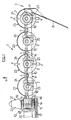
- FIG. 1 there is shown a mower or more precisely the cutter bar (1) of a mower.
- This cutter bar (1) comprises four discs (2,3) each rotating around an axis directed upwards.
- Each disc (2, 3) is provided with two cutting tools (4) which are mounted diametrically opposite on the outer edge of the disc.
- the cutting tools (4) are mounted on the discs (2, 3) so that said cutting tools (4) extend outwards under the effect of centrifugal force, and qu '' they can pivot backwards when they encounter an obstacle during their rotation.
- the disc (3) located at the right end (5) of the cutter bar (1), seen in the working direction defined by the arrow (6), is surmounted by a cap (7).
- This cover (7) collaborates with a device for reducing the swath of cut fodder such as the swath board (8) for example, so that the cut swath of fodder is separated from the forage still standing.
- the discs (2, 3) are guided in rotation in a casing (9) disposed under said discs.
- This casing (9), as will be explained below in more detail, is formed by a succession of modules (10).
- the casing (9) is provided with an end module (11) which extends substantially up to the external trajectory described by the disc ( 3), or slightly beyond said trajectory.
- the casing (9) is provided with a return casing (13).
- transmission means such as a transmission shaft (14) which collaborates with toothed wheels for example, with a view to rotating the discs (2, 3).
- the rotary drive of these transmission means is achieved by means of a drive mechanism housed in the gearbox (13) and which will be described later in more detail.
- This drive mechanism receives the movement of a pulley (15) wedged on the axis (16).
- the pulley (15) is rotated by means of another pulley not shown by means of belts (17).
- This other pulley is, in a manner known to those skilled in the art, driven by the power take-off of a tractor, not shown, to which the mower is coupled, by means of a universal joint shaft, not shown. .
- the gearbox (13) has two cylindrical surfaces (18) substantially concentric with the axis (16) of the input of said gearbox (13). These cylindrical bearings (18) support a yoke (19) fixed to a frame (20) by means of which the mower is coupled to the tractor. With this arrangement, the cutter bar (1) can follow the unevenness of the ground by pivoting around the axis of the cylindrical bearings (18) without the various drive members being subjected to additional stresses. Furthermore, it is possible to pivot the cutter bar (1) to a sensitive position vertical to reduce the width of the mower during transport.
- a shoe (21) which has a front part (22) raised like the front of 'a ski. This shoe (21) allows the mower to slide on the ground and avoid catching cut forage on the gearbox (13).
- disc protective pads At the front, under each disc (2, 3), the casing (9) is provided with disc protective pads (23). These disc protective pads have a front portion (24) having a top circular shape whose radius is larger than the radius of the extreme trajectory of the discs (2, 3) but smaller than the radius of the trajectory end of the cutting tools (4). Furthermore, said disc protective pads (23) have a back portion (25) in the form of a pad, on which also rests the cutter bar (1).
- the casing (9) comprises a plurality of modules (10).
- Each module (10) supports a disc (2, 3).
- the module (10) consists of a housing (26) in which said disc (2, 3) is guided in rotation, and a spacer (27) which extends between this housing (26) and the housing ( 26) of an adjacent module (10).
- the spacer (27) of a module (10) extends to the left of the housing (26) of the same module, seen in the direction of advance of the machine at work.
- the different modules (10) are centered relative to each other by means of a centering ring (28) which extends both inside the spacer (27) of a module (10) and inside the housing (26) of the adjacent module (10).
- the centering ring (28) has a length such that it can absorb part of the bending forces exerted on the cutter bar (1) during tra vail and during transport.
- the different modules (10) are linked to each other by means of assembly members (29). To do this, each module (10) has at each of its ends a flange (30).
- the flanges (30) of two adjacent modules (10) are linked together by the assembly members (29) which are constituted, in the embodiment described, by screws (31) whose rod (32) passes through the two adjacent flanges (30), and by nuts (33) screwed onto said rods (32).
- the flanges (30) each have a certain width so that the length of the screws (31) is sufficient to allow them to withstand the stresses to which they are subjected.
- the casing (9) thus formed contains a transmission shaft (14).
- the transmission shaft (14) collaborates with a pair of bevel gearwheels (34, 35) in order to transmit the movement to the corresponding disc (2, 3).
- the drive shaft (14) passes through the bore (36) of the toothed wheel (34) which has the shape complementary to that of the drive shaft (14).
- the drive shaft (14) has a hexagonal section (see Figure 4). It is however possible that the shaft has a section of another shape as soon as this shape allows a rotation drive. Similarly, it is possible that the drive shaft (14) has the shape allowing the rotational drive only in the area where it collaborates with the toothed wheel (34).
- the toothed wheel (34) is integral with a sleeve (37) which also surrounds the transmission shaft (14).
- the gear wheel (34) - sleeve (37) assembly is guided in rotation in the housing (26) by means of two bearings such as ball bearings (38, 39).
- the toothed wheel (34) has a cylindrical surface (40) on which is mounted the bearing (38) which abuts against a shoulder (41) of the toothed wheel (34).
- the sleeve (37) meanwhile, has at its end remote from the toothed wheel (34), also a cylindrical surface (42) on which is mounted the bearing (39) which abuts against a shoulder (43) of the sleeve ( 37).
- the bearings (38, 39) are thus mounted on the toothed wheel (34) - sleeve (37) assembly so that the teeth of the toothed wheel (34) are located between the two bearings (38, 39).
- the outer diameter of the bearings (38, 39) is the same, which has advantages in the production of the outer surfaces (44, 45) machined in the housing (26). Likewise, the length of said outer surfaces is reduced to a minimum to reduce machining times and facilitate assembly.
- the part (46) of the housing (26) located between the outer surfaces (44, 45) has a larger diameter than the diameter of the surfaces (44, 45).
- Maintaining in translation of the toothed wheel assembly (34) -forge (37) in the housing (26) is produced on the one hand by a shoulder (47) arranged in the housing (26), and on the other hand by a stop member such as a circlip (48). Between the bearing (39) and the stop member (48), thickness washers (49) have been arranged which allow the mounting to reduce or eliminate the axial play resulting from the different dimensional tolerances.
- sealing members such as the sealing rings (50, 40) have been arranged on the cylindrical surfaces (40, 42) of the toothed wheel (34) of the sleeve (37) respectively. 51) which act between the housing (26) and the toothed wheel (34) - sheath (37) assembly.
- the two sealing members (50, 51) are arranged so that the two bearings (38, 39) and the toothing of the toothed wheel (34) are located between the two sealing members (50, 51). With this arrangement, the housing (26) therefore remains sealed inde pending the presence of the drive shaft (14).
- the toothed wheel (34) meshes with the toothed wheel (35) which is integral with a disc shaft (52).
- the disc shaft (52) is guided in rotation in a bearing cylinder (53) by means of a bearing (54) which consists, in the embodiment described, of a rolling box (55) and a bearing (56).
- the bearing cylinder (53) is an integral part of the housing (26) and therefore of the module (10).
- the inner bore of the bearing cylinder (53) has a smooth part (57) and a threaded part (58).
- the outer surface of the bearing (54) also includes a smooth part (59) and a threaded part (60).
- the threading of the threaded parts (58, 60) is advantageously a fine pitch thread.
- the bearing (54) is centered in the bearing cylinder (53), and thanks to the threaded parts (58, 60), said bearing (54) is held in translation in said bearing cylinder (53).
- said paleir (54) is provided at its upper part with a thin cylindrical crown (61) which is partially deformed to collaborate with at least one notch (62) arranged in the upper part of the bearing cylinder (53).
- the bearing box (55) supports the bearing (56) which is centered in the bore of said bearing box.
- This bearing is in the example described, a double row bearing of angular contact balls. It is provided with integrated sealing means (63).
- the bearing (56) is held in translation in the bearing box (55) by means of two shoulders (64, 65).
- the shoulder (64) is produced by machining while the shoulder (65) is produced after mounting the bearing (56) in a manner which will be explained later.
- the disc shaft (52) - toothed wheel (35) assembly is centered in the bore of the bearing (56), the inner ring of which abuts against the shoulder (66) of the toothed wheel (35). Near its free end, the disc shaft (52) is provided with splines (67) which collaborate, with a view to the rotational drive of the disc (2, 3) with splines (68) arranged in a driver ( 69) secured to the disc (2, 3). In order to fix the disc (2, 3) on the disc shaft (52), the latter ends with a threaded part (70) which extends outside the driver (69), and on which is screwed a nut (71) after interposition of a washer (72).
- the bearing (56) is blocked between the shoulder (66) and the driver (69).
- the nut (71) is housed in a recess (73) arranged in the upper part of the driver (69).
- the mounting of a housing (26) is carried out as follows. First, the gear wheel (34) - sleeve (37) assembly is premounted, that is to say that the bearing (38) and then the sealing member (50) are mounted on the cylindrical part (40). ), and on the cylindrical part (42) the bearing (39). The assembly thus pre-assembled is then threaded into the housing (26) until the bearing (38) abuts against the shoulder (47). The number of washers of thickness (49) is then put in place and the assembly is locked axially using the stop member (48). The housing (26) is then sealed by mounting the sealing member (51). The gear wheel (35) - disc shaft (52) - bearing (54) is then premounted.
- the bearing (54) is mounted on the disc shaft (52) until it abuts on the shoulder (66). This assembly is then mounted in the bearing cylinder (53). This is possible because the smaller diameter of the bearing cylinder bore (53) is more larger than the outside diameter of the gear wheel (35).
- the bearing (54) first centers in the bearing cylinder (53) via the smooth parts (57, 59) before the threaded parts (58, 60) can be screwed one inside the other. This ensures that the two threaded parts (58, 60) are opposite one another, which makes it possible to avoid trial and error when the screwing begins.
- the threaded parts (58, 60) are arranged in such a way in the housing (26) respectively on the bearing (54), relative to the toothed wheels (34, 35), so that said threaded parts (58, 60 ) cannot be engaged when a tooth of the toothed wheel (35) abuts on a tooth of the toothed wheel (34).
- the screwing can then only be carried out when one of the toothed wheels has been slightly turned relative to the other.
- the bearing (54) is then screwed into the bearing cylinder (53), the toothed wheel (35) is brought closer to the toothed wheel (34).
- the screwing of the bearing (54) is stopped. in the bearing cylinder (53). To maintain this position, a part of the thin cylindrical crown (61) is deformed to make it penetrate into at least one notch (62). It will be noted that to facilitate the subsequent screwing and unscrewing during an intervention, the bearing (54) is provided with at least one gripping means such as the recess (74).
- the bearing (54) Since the bearing (54) is not centered in the bearing cylinder (53) with tightening, and depending on the nature of the lubricant contained in the housing (26), it may prove necessary to prevent said lubricant from leak between said bearing (54) and said bearing cylinder (53). To do this, it is possible to have between these two parts of the sealing means, such as an adhesive deposited for example between the bearing (54) and the bearing cylinder (53).
- the gear (34) extends to the left of the disc shaft (52). This position therefore defines a direction of rotation of the corresponding disc.
- the assembly must therefore be done so that the corresponding toothed wheel (34) extends to the right of the disc axis (52), the drive shaft (14) rotating. always in the same direction.
- the assembly of the toothed wheel (34) - sleeve (37) assembly in the corresponding housing (26) will be carried out as follows.
- the sealing member (50) will be mounted on the cylindrical part (42) and the assembly will be threaded into the casing (26) sleeve (37) first, until the bearing (39) abuts against the shoulder (47).
- the outer surface of the latter has two zones (75 and 76).
- the area (75) is located in the upper part of the outer surface of the bearing cylinder (53) and extends inside a bore (77) made in the driver (69).
- the diameter of the bore (77) is slightly larger than the diameter of the zone (75) in order to form a baffle.
- the zone (76) extends from the zone (75) downwards, and has a smaller diameter than that of the area (75). In addition, the length of the zone (76) is relatively large.
- the lower surface (78) of the driver (69) extends substantially in the vicinity of the border between the zones (75 and 76) and preferably slightly higher than said border.
- the lower surface (78) of the driver (69) can extend from the vicinity of the border between the zones (75 and 76) outwards and upwards.
- An exemplary embodiment of such an arrangement is shown in Figure 5 where the lower surface (78) of the driver (69) is substantially conical. With this arrangement, the risks of winding up strands of fodder or filiform bodies are substantially reduced since the space between the fixed locations where the strands of fodder or filiform bodies could catch on and the rotating disc is relatively large.
- Figure 3 shows a top view of the cutter bar (1).
- the discs (2, 3) have been drawn in phantom.
- the axis (79) of the bearing cylinder (53) which also corresponds to the axis of rotation of the corresponding disc (2, 3) is located closer to the front edge (80) of the housing ( 9) only from the rear edge (81) of this casing.
- the overcut triangle (82) which is defined by the front intersection point (83) of the extreme trajectories (84, 85) described by the cutting tools (4) of two adjacent discs, and the front edge (80) of the casing (9), is very large. This ensures a good cut of the forage between two adjacent discs.
- This disc protective pad (23) comprises, as said above, a front part (24) having a substantially circular shape and substantially centered on the axis (79).
- the disc protective pad (23) is fixed to the casing (9) by means of a number of fixing members (86), three in the example described. These fasteners (86) extend near the front edge (80) and the rear edge (81) of the housing (9).
- the assembly members (29) which link the different modules (10) together also extend at the front and at the rear of the flanges (30).
- the distance (87) between the assembly members (29) which extend at the front, and those which extend at the rear, is relatively large so that the connection between the modules (10) is very resistant.
- Figure 4 shows a cross section of the cutter bar (1).
- the disc protective pads (23) partially fit on the front edge (80) of the housing (9).
- the front edge (80) of the spacer (27) has a relatively pointed shape. Thanks to this shape, the risks of sticking of soil or plant debris to said front edge (80) are reduced, which would reduce the quality of the cut. It should be noted that the spacer (27) has this pointed shape at least in the zone (89) which extends between two neighboring disks (2, 3) where the cutting tools (4) pass over the casing (9) during their rotation (see Figure 3).
- the lower face (90) of the spacer (27) extends at a certain distance (91) from the surface of the ground (92).
- this space between the underside (90) of the spacer (27) and the ground surface (92) preferably extends over the entire length of the spacer (27).
- the front edge (80) of the spacer (27) advantageously has an inclined plane (93) directed backwards and downwards. This inclined plane (93) extends at least in the area (89) of the front edge (80).
- the front edge (80) also has an inclined plane (94) directed upwards and backwards. With this shape, the impact between a cutting tool (4) accidentally bent downwards and the front edge (80) is reduced. In addition, given the speed of rotation, the inclined plane (94) can somewhat straighten a bent cutting tool (4).
- the upper part of the front edge (80) at least has a greater thickness of material than the rest of the cross section of the spacer (27). It should be noted that the inclined plane (94) and the place where the thickness of material is greater extend at least in the zone (89) (see FIG. 3). When a cutting tool (4) folded down has not been able to be fully straightened, it can then strike the rear edge (81) of the adjacent module (10) in the zone (95) above which it passes during of its rotation towards the casing (9).
- the rear edge (81) of the spacer (27) has at least in the area (95), an inclined plane (96) directed forwards and upwards.
- the thickness of material in this area is also greater than in the rest of the cross section of the spacer (27).
- At least one rib (97) which connects the lower face (90) to the upper face (98) of the spacer (27) .
- This rib (97) can even extend into the housing (26) and connect the two flanges (30) of a module (10).
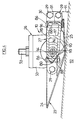
- Figure 5 shows the ends (5) and (12) of the cutter bar (1).
- the cutter bar (1) comprises, as said previously, an end module (11) which closes the end (5) of the cutter bar (1).
- This end module (11) extends to the extreme trajectory of the disc (3) or slightly beyond.
- the end module (11) can protect, to a certain extent, laterally the disc (3).
- the swath board (8) is fixed to the end module (11) using the assembly members (29) which fix said end module (11) to the module (10) which supports the disc. (3), and with the aid of liaison bodies (99).
- the gearbox (13) contains a drive mechanism which transmits the movement of the pulley (15) to the drive shaft (14).
- This drive mechanism consists of the following organs.
- a toothed wheel (100) is wedged on the axis (16) on which the pulley (15) is also wedged.
- This toothed wheel (100) meshes with a toothed wheel (101) which is wedged on an axis (102) which extends substantially perpendicular to the axis (16) and substantially parallel to the drive shaft (14).
- On the axis (102) is also wedged a cylindrical toothed wheel (103) which meshes with another cylindrical toothed wheel (104) wedged on an axis (105).
- the axis (105) extends substantially parallel to the axis (102).
- This cylindrical gear (104) meshes with a third cylindrical gear (106) wedged on the drive shaft (14).
- the axes (102 and 105) are guided in rotation in the gearbox (13) by means of bearings such as bearings known to those skilled in the art.
- the cylindrical toothed wheel (106) has a cylindrical part (107) which extends concentrically on either side of its teeth and which serves as a bearing for bearings such as the bearings (108, 109) guiding said wheel in rotation. toothed (106).
- the gearwheel (106) stops in translation by means of a shoulder (110) arranged in the gearbox (13) and a circlip (111).
- the gearbox (13) also has at its base sealing members (112, 113) which extend between the walls of said gearbox (13) and the cylindrical part (107) in order to make the gearbox waterproof regardless of the presence of the drive shaft (14).
- the cylindrical part (107) has a bore (114) having the shape complementary to that of the transmission shaft (14), in order to cooperate with this transmission shaft (14) which partially extends inside said bore (114).
- the gear wheel (106) - cylindrical part (107) assembly includes a stop member (115) which is rigidly connected to this assembly or at least linked in translation compared to this one.
- a screw (116) is screwed into a threaded hole (117) arranged at the end of the transmission shaft (14 ).
- Figure 6 shows how to form the shoulder (65).
- the tool (120) Before mounting the bore (118) of the rolling box (55) opens onto the face (119) of the rolling box (55) as shown in phantom.
- the tool (120) After mounting the bearing (56) in the bore (118), the tool (120) is pressed into the face (119), which has the effect of deforming the location of the bore (118) which opens onto the face (119).
- the deformation causes a displacement of the material towards the axis of the bearing box (55) which then maintains the bearing (56) in said bearing box (55).
- Figure 7 shows another embodiment of the bearing (54).
- it is a special bearing (56), the outer ring of which is large enough to be centered in the bearing cylinder (53).
- the outer ring of this bearing (56) has a shoulder (121).
- the bore of the bearing cylinder (53) has a shoulder (122).
- an O-ring (123) Between the shoulders (121 and 122) is arranged an O-ring (123).
- the bearing (56) is held axially in the bearing cylinder (53) by means of the shoulders (121 and 122) and the O-ring (123), and by means of a circlip (124) after interposition d 'a washer (125) and thick washers (126).
- the mounting of the bearing (54) in the bearing cylinder (53) and the adjustment of the operating clearance of the toothed wheels (34, 35) are carried out in this case as follows.
- the bearing (54) maintains its position in the bearing cylinder (53). It should be noted that the O-ring (123) also prevents leakage of the lubricant contained in the housing (26), between the bearing (54) and the bearing cylinder (53).
- the O-ring (128) prevents leakage of lubricant between the bearing (54) and the disc shaft (52).
- Figures 8 and 9 show an alternative embodiment of the gripping means which allow the screwing or unscrewing of the bearing (54).
- These means are constituted by a central part (129) which emerges from the upper face of the bearing (54) and which has a non-circular and preferably polygonal external surface. In the example shown, this outer surface is hexagonal. It is thus possible to use a conventional key to screw or unscrew the bearing (54).
- the transmission shaft (14) can be made in several parts. Furthermore, the zones of the transmission shaft (14) where the latter cooperates with a toothed wheel (106, 34) may have a larger nominal dimension than the rest of the transmission shaft (14). In addition, the bearing (54) could also be a plain bearing.
Landscapes
- Life Sciences & Earth Sciences (AREA)
- Environmental Sciences (AREA)
- Harvester Elements (AREA)
- Centrifugal Separators (AREA)
- Iron Core Of Rotating Electric Machines (AREA)
- Supercharger (AREA)
- Input Circuits Of Receivers And Coupling Of Receivers And Audio Equipment (AREA)
Abstract
Dans la faucheuse rotative, Selon l'invention, le plus petit diamètre de l'alésage du cylindre de palier (53) faisant partie intégrante du carter (9) est supérieur au diamètre extérieur de la roue (35) fixée sur l'arbre (52), de telle sorte que l'ensemble prémonté arbre (52) - roue (35) -palier (54) puisse être monté dans l'alésage du cylindre de palier (53) et démonté dudit alésage.In the rotary mower, according to the invention, the smallest diameter of the bore of the bearing cylinder (53) forming an integral part of the casing (9) is greater than the outside diameter of the wheel (35) fixed on the shaft ( 52), so that the pre-assembled shaft (52) - wheel (35) -stair (54) assembly can be mounted in the bore of the bearing cylinder (53) and disassembled from said bore.
Description
La présente invention concerne une faucheuse comportant des organes de coupe rotatifs munis d'au moins un outil de coupe, au moins un desdits organes de coupe rotatifs étant entraîné par des moyens de transmission logés dans un carter situé sous lesdits organes de coupe rotatifs, lesdits moyens de transmission comportant une roue solidaire de l'arbre de l'organe de coupe rotatif entraîné par le bas qui est guidé en rotation dans un palier logé dans l'alésage d'un cylindre de palier faisant partie intégrante du carter.The present invention relates to a mower comprising rotary cutting members provided with at least one cutting tool, at least one of said rotary cutting members being driven by transmission means housed in a casing situated under said rotary cutting members, said transmission means comprising a wheel integral with the shaft of the rotary cutting member driven from below which is guided in rotation in a bearing housed in the bore of a bearing cylinder forming an integral part of the casing.
Une telle faucheuse présente des avantages certains, dans le mesure où, pour lier le cylindre de palier au carter, il n'y a pas à réaliser d'usinages complexes sur le cylindre de palier et le carter, ni à prévoir d'organes d'assemblage complexes. Une telle liaison peut en effet être directement réalisée par moulage par exemple lorsque le carter comporte des éléments en fonte, ou être réalisée par un procédé de soudage.Such a mower has certain advantages, in that, in order to link the bearing cylinder to the housing, there is no need to carry out complex machining on the bearing cylinder and the housing, nor to provide for components 'complex assembly. Such a connection can in fact be made directly by molding, for example when the casing comprises cast iron elements, or be made by a welding process.
On connait en effet une telle faucheuse dont les cylindres de palier sont soudés au couvercle du carter. Chaque arbre d'un organe de coupe rotatif entraîné par le bas, est guidé en rotation dans son cylindre de palier correspondant au moyen d'un palier constitué par deux roulements. La roue, solidaire de chacun de ces arbres, est une roue dentée cylindrique qui engrène avec d'autres roues dentées cylindriques. Avec cette faucheuse connue, il est nécessaire, lors d'une intervention sur un palier par exemple, d'ouvrir tout le carter. Pour ce faire, il faudra tout d'abord démonter le carter du châssis de la faucheuse, vidanger le lubrifiant qu'il contient, servant à la lubrification des roues dentées cylindriques, ouvrir ledit carter, procéder à la réparation, refermer ledit carter, remettre la quantité nécessaire de lubrifiant et enfin remonter ledit carter sur le châssis. Il est évident qu'une telle invervention ne peut se faire qu'en atelier. Ceci nécessite en conséquence, une immobilisation de la machine relativement longue et occasionne des frais de réparation très importants.We know in fact such a mower whose bearing cylinders are welded to the housing cover. Each shaft of a rotary cutting member driven from below, is guided in rotation in its corresponding bearing cylinder by means of a bearing constituted by two bearings. The wheel, integral with each of these shafts, is a cylindrical toothed wheel which meshes with other cylindrical toothed wheels. With this known mower, it is necessary, during an intervention on a bearing for example, to open the entire casing. To do this, it will be necessary first of all dismantle the casing of the mower chassis, drain the lubricant it contains, used for the lubrication of cylindrical toothed wheels, open said casing, carry out the repair, close said casing, refill the necessary quantity of lubricant and finally reassemble said casing on the chassis. It is obvious that such invervention can only be done in the workshop. This therefore requires a relatively long downtime of the machine and incurs very high repair costs.
En sus, il n'est pas non plus possible de bien organiser le montage de cette faucheuse connue. En effet, avec cette construction, il n'est pas possible de prémonter des petits sous-ensembles, de sorte que le montage de cette faucheuse ne peut pas être fait de manière économique.In addition, it is also not possible to properly organize the assembly of this known mower. Indeed, with this construction, it is not possible to pre-assemble small sub-assemblies, so that the mounting of this mower cannot be done economically.
Le but de la présente invention est, en conséquence, de modifier les faucheuses connues de telle sorte, que leur montage puisse être fait de manière économique et que les interventions ultérieures puissent être réalisées très rapidement et sans occasionner de frais importants.The object of the present invention is, therefore, to modify the known mowers so that their mounting can be done economically and that subsequent interventions can be carried out very quickly and without incurring significant costs.
Dans ce but, la faucheuse selon l'invention est caractérisée par le fait que le plus petit diamètre de l'alésage du cylindre de palier est supérieur au diamètre extérieur de la roue fixée sur l'arbre, de telle sorte que l'ensemble prémonté arbre - roue - palier puisse être monté dans l'alésage du cylindre de palier et démonté dudit alésage.For this purpose, the mower according to the invention is characterized in that the smallest diameter of the bore of the bearing cylinder is greater than the outside diameter of the wheel fixed on the shaft, so that the assembly pre-assembled shaft - wheel - bearing can be mounted in the bore of the bearing cylinder and disassembled from said bore.
Grâce à cette caractéristique, le montage de la faucheuse selon l'invention peut être fait de manière très économique. En effet, l'ensemble arbre - roue - palier qui représente une petite unité, peut être prémonté avant le montage final. Comme cet ensemble est compact, ce prémontage peut même être automatisé.Thanks to this characteristic, the mounting of the mower according to the invention can be done very easily. economic. Indeed, the shaft - wheel - bearing assembly, which represents a small unit, can be pre-assembled before final assembly. As this assembly is compact, this pre-assembly can even be automated.
Lorsqu'au cours du travail, il arrive un incident sur un ensemble arbre - roue - palier, il suffira de démonter cet ensemble défectueux du cylindre de palier, puis de le remplacer par un nouvel ensemble. Compte tenu de la simplicité de cette intervention, celle-ci peut être réalisée dans le champ même. Ceci immobilisera donc la machine pendant un temps très limité, ce qui est capital pendant la période de récolte au cours de laquelle les pertes de temps ne sont pas tolérables, et occasionnera des frais très modestes.When, during work, an incident occurs on a shaft - wheel - bearing assembly, it will suffice to disassemble this defective assembly from the bearing cylinder, then replace it with a new assembly. Given the simplicity of this intervention, it can be carried out in the field itself. This will therefore immobilize the machine for a very limited time, which is essential during the harvest period during which the loss of time is not tolerable, and will cause very modest costs.
Selon une réalisation préférée, le palier qui guide en rotation l'arbre de l'organe de coupe rotatif correspondant, comporte une boîte à roulement et au moins un roulement. Avantageusement, le ou les roulements sont montés dans la boîte à roulement de manière indémontable.According to a preferred embodiment, the bearing which guides the shaft of the corresponding rotary cutting member in rotation, comprises a rolling box and at least one bearing. Advantageously, the bearing or bearings are mounted in the bearing box in a non-removable manner.
Selon une caractéristique supplémentaire, le montage comporte des moyens qui permettent un réglage sensiblement continu du jeu de fonctionnement des moyens de transmission tels que couples de roues dentées par exemple. Avec cette caractéristique, il est possible sans augmenter les coûts de montage, de régler de manière précise le jeu de fonctionnement des moyens de transmission. Un réglage précis de ce jeu de fonctionnement entraîne notamment une durée de vie plus importante des moyens de transmission et un abaissement du niveau sonore lors du fonctionnement de la faucheuse.According to an additional characteristic, the assembly comprises means which allow a substantially continuous adjustment of the operating clearance of the transmission means such as pairs of toothed wheels for example. With this characteristic, it is possible, without increasing the assembly costs, to precisely regulate the operating clearance of the transmission means. A precise adjustment of this operating clearance leads in particular to a longer life of the transmission means and a lowering of the sound level during the operation of mower.
Selon une forme de réalisation, les moyens qui permettent ce réglage sont constitués par au moins un organe que l'on déforme lors du montage du palier dans le cylindre de palier.According to one embodiment, the means which allow this adjustment consist of at least one member which is deformed during mounting of the bearing in the bearing cylinder.
Selon une autre forme de réalisation, c'est le palier qui comporte sur sa surface extérieure une partie au moins qui est filetée, et qui collabore avec une partie filetée de l'alésage du cylindre de palier. Cette dernière forme de réalisation permet d'avoir une plage importante de réglage. Le réglage est d'autant plus fin que le pas de filetage est fin.According to another embodiment, it is the bearing which has on its external surface at least a part which is threaded, and which collaborates with a threaded part of the bore of the bearing cylinder. This latter embodiment makes it possible to have a large range of adjustment. The adjustment is all the more fine as the thread pitch is fine.
Avantageusement, la surface extérieure du palier comporte une partie non filetée qui se centre dans une partie non filetée du cylindre de palier. Cette disposition permet d'avoir un bon centrage de l'arbre de l'organe de coupe rotatif dans le cylindre de palier.Advantageously, the outer surface of the bearing comprises an unthreaded part which centers in an unthreaded part of the bearing cylinder. This arrangement makes it possible to have good centering of the shaft of the rotary cutting member in the bearing cylinder.
Selon une réalisaition préférée, les parties non filetées du palier et du cylindre de palier coopèrent avant que les parties filetées dudit palier et dudit cylindre de palier ne commencent à être en prise. Cet agencement permet de visser aisément le palier dans le cylindre de palier. En effet, comme le palier est déjà centré dans le cylindre de palier avant le vissage, tout tâtonnement, pour amener la partie filetée du palier et celle du cylindre de palier en face l'une de l'autre pour que le vissage puisse effectivement être entrepris, est éliminé.According to a preferred embodiment, the non-threaded parts of the bearing and of the bearing cylinder cooperate before the threaded parts of said bearing and of said bearing cylinder begin to be engaged. This arrangement allows the bearing to be easily screwed into the bearing cylinder. Indeed, as the bearing is already centered in the bearing cylinder before screwing, any trial and error, to bring the threaded part of the bearing and that of the bearing cylinder opposite one another so that the screwing can actually be undertaken, is eliminated.
Par ailleurs, les parties filetées du palier et du cylindre de palier sont agencées de telle manière qu'elles ne peuvent pas être amenées en prise l'une avec l'autre lorsque, au cours du montage, les moyens de transmission tels que le couple de roues dentées par exemple, ne sont pas en prise. Cette caractéristique est très avantageuse au niveau du montage. En effet, elle permet l'emploi de machines visseuses sans risquer de bloquer le palier dans le cylindre de palier alors que les moyens de transmisson ne sont pas en prise. Cette caractéristique réduit donc les aléas au montage et corrélativement également les coûts de montage.Furthermore, the threaded parts of the bearing and of the bearing cylinder are arranged in such a way that they cannot be brought into engagement with one another when, during assembly, the transmission means such as the pair of toothed wheels for example, are not in engagement. This characteristic is very advantageous in terms of mounting. Indeed, it allows the use of screwing machines without risking blocking the bearing in the bearing cylinder while the transmission means are not engaged. This characteristic therefore reduces the risks of assembly and correlatively also the assembly costs.
Selon une caractéristique supplémentaire, après montage du palier dans le cylindre de palier, des moyens condamnent le rotation relative entre ledit palier et ledit cylindre de palier.According to an additional characteristic, after mounting of the bearing in the bearing cylinder, means condemn the relative rotation between said bearing and said bearing cylinder.
Ces moyens sont particulèrement efficaces lorsqu'ils sont constitués par au moins un organe du palier qui collabore avec un organe du cylindre de palier.These means are particularly effective when they are constituted by at least one bearing member which collaborates with a member of the bearing cylinder.
Avantageusement ces organes sont amenés en collaboration par déformation de l'un et/ou de l'autre.Advantageously, these members are brought into collaboration by deformation of one and / or the other.
Cet agencement permet ainsi de maintenir précisément le jeu de fonctionnement des moyens de transmission sans entraîner des coûts de montage élevés.This arrangement thus makes it possible to precisely maintain the operating clearance of the transmission means without causing high mounting costs.
Selon une caractéristique supplémentaire, le palier est muni de moyens de prise qui permettent son vissage et son dévissage.According to an additional characteristic, the bearing is provided with gripping means which allow its screwing and unscrewing.
Suivant une forme de réalisation, ces moyens sont constiutés par au moins un creux aménagé dans la face supérieure du palier. Il est ainsi possible de pouvoir démonter le palier avec un outil de frappe tel qu'un marteau, sans risquer de casser lesdits moyens de prise.According to one embodiment, these means are constituted by at least one recess arranged in the upper face of the bearing. It is thus possible to be able to disassemble the bearing with a striking tool such as a hammer, without risking breaking said gripping means.
Suivant une autre forme de réalisation, les moyens de prise sont constitués par une partie centrale qui émerge à la face supérieure du palier et qui a une surface extérieure non circulaire et de préférence polygonale.According to another embodiment, the gripping means are constituted by a central part which emerges at the upper face of the bearing and which has a non-circular and preferably polygonal outer surface.
Selon une caractéristique supplémentaire, des moyens d'étanchéité empêchent les fuites de lubrifiant entre le palier et le cylindre de palier.According to an additional feature, sealing means prevent leakage of lubricant between the bearing and the bearing cylinder.
D'autres caractéristiques de la faucheuse selon l'invention sont contenues dans les autres sous -revendications et appraîtront ci-après plus en détail dans la description suivante d'une forme de réalisation non limitative en référence au dessin annexé sur lequel :
- - La figure 1 représente une vue de dessus de la barre de coupe de la faucheuse selon l'invention.
- - La figure 2 représente une vue arrière en coupe selon le plan II-II défini sur la figure 1.
- - La figure 3 représente une vue de dessus à une échelle agrandie de la barre de coupe sans disques.
- - La figure 4 représente une vue latérale en coupe selon le plan IV-IV défini sur la figure 3.
- - La figure 5 représente une vue arrière partiellement en coupe des extrémités de la barre de coupe.
- - La figure 6 représente la méthode de formation d'un épaulement pour maintenir le roulement d'un disque dans la boîte à roulement.
- - La figure 7 représente une autre forme de réalisation du palier qui guide en rotation un disque.
- - La figure 8 représente une vue en coupe d'une autre forme de réalisation d'une boîte à roulement.
- - La figure 9 représente une vue de dessus de la boîte à roulement de la figure 8.
- - Figure 1 shows a top view of the cutter bar of the mower according to the invention.
- - Figure 2 shows a rear sectional view along the plane II-II defined in Figure 1.
- - Figure 3 shows a top view on an enlarged scale of the cutter bar without discs.
- FIG. 4 represents a side view in section along the plane IV-IV defined in FIG. 3.
- - Figure 5 shows a partially sectioned rear view of the ends of the cutter bar.
- - Figure 6 shows the method of forming a shoulder to maintain the rolling of a disc in the bearing box.
- - Figure 7 shows another embodiment of the bearing which guides in rotation a disc.
- - Figure 8 shows a sectional view of another embodiment of a rolling box.
- FIG. 9 represents a top view of the rolling box of FIG. 8.
Sur la figure 1, est représentée une faucheuse ou plus précisément la barre de coupe (1) d'une faucheuse. Cette barre de coupe (1) comporte quatre disques (2,3) tournant chacun autour d'un axe dirigé vers le haut. Chaque disque (2, 3) est muni de deux outils de coupe (4) qui sont montés diamétralement opposés sur la bordure extérieure du disque. De préférence, le montage des outils de coupe (4) sur les disques (2, 3) est réalisé de sorte que lesdits outils de coupe (4) s'étendent vers l'extérieur sous l'effet de la force centrifuge, et qu'ils puissent pivoter vers l'arrière lorsqu'ils rencontrent un obstacle lors de leur rotation. Le disque (3) situé à l'extrémité droite (5) de la barre de coupe (1), vue dans le sens de travail défini par la flèche (6), est surmonté d'une coiffe (7). Cette coiffe (7) collabore avec un dispositif de réduction de l'andain de fourrage coupé tel que la planche à andains (8) par exemple, de sorte que l'andain de fourrage coupé soit séparé du fourrage encore sur pied.In Figure 1, there is shown a mower or more precisely the cutter bar (1) of a mower. This cutter bar (1) comprises four discs (2,3) each rotating around an axis directed upwards. Each disc (2, 3) is provided with two cutting tools (4) which are mounted diametrically opposite on the outer edge of the disc. Preferably, the cutting tools (4) are mounted on the discs (2, 3) so that said cutting tools (4) extend outwards under the effect of centrifugal force, and qu '' they can pivot backwards when they encounter an obstacle during their rotation. The disc (3) located at the right end (5) of the cutter bar (1), seen in the working direction defined by the arrow (6), is surmounted by a cap (7). This cover (7) collaborates with a device for reducing the swath of cut fodder such as the swath board (8) for example, so that the cut swath of fodder is separated from the forage still standing.
Les disques (2, 3) sont guidés en rotation dans un carter (9) disposé sous lesdits disques. Ce carter (9), tel qu'il sera expliqué plus loin plus en détail, est formé par une succession de modules (10). A l'extrémité droite (5) de la barre de coupe (1), le carter (9) est muni d'un module d'extrémité (11) qui s'étend sensiblement jusqu'à la trajectoire extérieure décrite par le disque (3), ou légèrement au-delà de ladite trajectoire. A l'extrémité gauche (12), le carter (9) est muni d'un carter de renvoi (13).The discs (2, 3) are guided in rotation in a casing (9) disposed under said discs. This casing (9), as will be explained below in more detail, is formed by a succession of modules (10). At the right end (5) of the cutter bar (1), the casing (9) is provided with an end module (11) which extends substantially up to the external trajectory described by the disc ( 3), or slightly beyond said trajectory. At the left end (12), the casing (9) is provided with a return casing (13).
Dans le carter (9) sont logés des moyens de transmission tels qu'un arbre de transmission (14) qui collabore avec des roues dentées par exemple, en vue d'entraîner en rotation les disques (2, 3). L'entraînement en rotation de ces moyens de transmission est réalisé par l'intermédiaire d'un mécanisme d'entraînement logé dans le carter de renvoi (13) et qui sera décrit ultérieurement plus en détail. Ce mécanisme d'entraînement reçoit le mouvement d'une poulie (15) calée sur l'axe (16). La poulie (15) est entraînée en rotation au moyen d'une autre poulie non représentée par l'intermédiaire de courroies (17). Cette autre poulie est, d'une manière connue de l'homme de l'art, entraînée par la prise de force d'un tracteur non représenté auquel est attelée la faucheuse, par l'intermédiaire d'un arbre à joints universels non représenté.In the casing (9) are housed transmission means such as a transmission shaft (14) which collaborates with toothed wheels for example, with a view to rotating the discs (2, 3). The rotary drive of these transmission means is achieved by means of a drive mechanism housed in the gearbox (13) and which will be described later in more detail. This drive mechanism receives the movement of a pulley (15) wedged on the axis (16). The pulley (15) is rotated by means of another pulley not shown by means of belts (17). This other pulley is, in a manner known to those skilled in the art, driven by the power take-off of a tractor, not shown, to which the mower is coupled, by means of a universal joint shaft, not shown. .
Le carter de renvoi (13) comporte deux portées cylindriques (18) sensiblement concentriques avec l'axe (16) d'entrée dudit carter de renvoi (13). Ces portées cylindriques (18) supportent une chape (19) fixée à un châssis (20) par l'intermédiaire duquel la faucheuse est attelée au tracteur. Avec cet agencement, la barre de coupe (1) peut suivre les dénivellations du sol en pivotant autour de l'axe des portées cylindriques (18) sans que les divers organes d'entraînement ne soient soumis à des contraintes supplémentaires. Par ailleurs, il est possible de pivoter la barre de coupe (1) dans une position sensible ment verticale pour réduire la largeur de la faucheuse au transport.The gearbox (13) has two cylindrical surfaces (18) substantially concentric with the axis (16) of the input of said gearbox (13). These cylindrical bearings (18) support a yoke (19) fixed to a frame (20) by means of which the mower is coupled to the tractor. With this arrangement, the cutter bar (1) can follow the unevenness of the ground by pivoting around the axis of the cylindrical bearings (18) without the various drive members being subjected to additional stresses. Furthermore, it is possible to pivot the cutter bar (1) to a sensitive position vertical to reduce the width of the mower during transport.
A l'extrémité (12) du carter (9) et sous celui-ci ou plus précisément sous le carter de renvoi (13), est agencé un sabot (21) qui a une partie avant (22) relevée comme l'avant d'un ski. Ce sabot (21) permet à la faucheuse de glisser sur le sol et d'éviter les accrochages de fourrage coupé au carter de renvoi (13).At the end (12) of the casing (9) and under it or more precisely under the gearbox (13), is arranged a shoe (21) which has a front part (22) raised like the front of 'a ski. This shoe (21) allows the mower to slide on the ground and avoid catching cut forage on the gearbox (13).
A l'avant, sous chaque disque (2, 3), le carter (9) est muni de patins protecteurs de disque (23). Ces patins protecteurs de disque comportent une partie frontale (24) présentant en vue de dessus une forme sensiblement circulaire dont le rayon est plus grand que le rayon de la trajectoire extrême des disques (2, 3) mais plus petit que le rayon de la trajectoire extrême des outils de coupe (4). Par ailleurs, lesdits patins protecteurs de disque (23) comportent une partie arrière (25) en forme de patin, sur laquelle repose également la barre de coupe (1).At the front, under each disc (2, 3), the casing (9) is provided with disc protective pads (23). These disc protective pads have a front portion (24) having a top circular shape whose radius is larger than the radius of the extreme trajectory of the discs (2, 3) but smaller than the radius of the trajectory end of the cutting tools (4). Furthermore, said disc protective pads (23) have a back portion (25) in the form of a pad, on which also rests the cutter bar (1).
Sur la figure 2, on voit une coupe de la barre de coupe (1). Comme dit plus haut, le carter (9) comporte une pluralité de modules (10). Chaque module (10) supporte un disque (2, 3). Le module (10) se compose d'un boîtoer (26) dans lequel est guidé en rotation ledit disque (2, 3), et d'une entretoise (27) qui s'étend entre ce boîtier (26) et le boîtier (26) d'un module (10) adjacent. Avantageusement, l'entretoise (27) d'un module (10) s'étend à gauche du boîtier (26) du même module, vu dans le sens d'avance de la machine au travail. Les différerents modules (10) sont centrés l'un par rapport à l'autre au moyen d'une bague de centrage (28) qui s'étend à la fois à l'intérieur de l'entretoise (27) d'un module (10) et à l'intérieur du boîtier (26) du module (10) adjacent. La bague de centrage (28) a une longueur telle qu'elle puisse absorber une partie des efforts de flexion qui s'exercent sur la barre de coupe (1) pendant le tra vail et pendant le transport. Les différents modules (10) sont liés l'un à l'autre au moyen d'organes d'assemblage (29). Pour ce faire, chaque module (10) comporte à chacune de ses extrémités une bride (30). Les brides (30) de deux modules (10) adjacents sont liées entre elles par les organes d'assemblage (29) qui sont constitués, dans l'exemple de réalisation décrit, par des vis (31) dont la tige (32) traverse les deux brides (30) adjacentes, et par des écrous (33) vissés sur lesdites tiges (32). Les brides (30) ont chacune une certain largeur de sorte que la longueur des vis (31) soit suffisante pour leur permettre d'encaisser les solliciations auxquelles elles sont soumises.In Figure 2, we see a section of the cutter bar (1). As said above, the casing (9) comprises a plurality of modules (10). Each module (10) supports a disc (2, 3). The module (10) consists of a housing (26) in which said disc (2, 3) is guided in rotation, and a spacer (27) which extends between this housing (26) and the housing ( 26) of an adjacent module (10). Advantageously, the spacer (27) of a module (10) extends to the left of the housing (26) of the same module, seen in the direction of advance of the machine at work. The different modules (10) are centered relative to each other by means of a centering ring (28) which extends both inside the spacer (27) of a module (10) and inside the housing (26) of the adjacent module (10). The centering ring (28) has a length such that it can absorb part of the bending forces exerted on the cutter bar (1) during tra vail and during transport. The different modules (10) are linked to each other by means of assembly members (29). To do this, each module (10) has at each of its ends a flange (30). The flanges (30) of two adjacent modules (10) are linked together by the assembly members (29) which are constituted, in the embodiment described, by screws (31) whose rod (32) passes through the two adjacent flanges (30), and by nuts (33) screwed onto said rods (32). The flanges (30) each have a certain width so that the length of the screws (31) is sufficient to allow them to withstand the stresses to which they are subjected.
Le carter (9) ainsi formé, contient un arbre de transmission (14). En traversant chaque boîtier (26), l'arbre de transmission (14) collabore avec un couple de roues dentées coniques (34, 35) en vue de transmettre le mouvement au disque (2, 3) correspondant. Pour ce faire, l'arbre de transmission (14) traverse l'alésage (36) de la roue dentée (34) qui possède la forme complémentaire de celle de l'arbre de transmission (14). Dans l'exemple décrit, l'arbre de transmission (14) a une section hexagonale (voir figure 4). Il est cependant possible que l'arbre ait une section d'une autre forme dès lors que cette forme permet un entraînement en rotation. De même, il est possible que l'arbre de transmission (14) ne présente la forme permettant l'entraînement en rotation que dans la zone où il collabore avec la roue dentée (34).The casing (9) thus formed contains a transmission shaft (14). By passing through each housing (26), the transmission shaft (14) collaborates with a pair of bevel gearwheels (34, 35) in order to transmit the movement to the corresponding disc (2, 3). To do this, the drive shaft (14) passes through the bore (36) of the toothed wheel (34) which has the shape complementary to that of the drive shaft (14). In the example described, the drive shaft (14) has a hexagonal section (see Figure 4). It is however possible that the shaft has a section of another shape as soon as this shape allows a rotation drive. Similarly, it is possible that the drive shaft (14) has the shape allowing the rotational drive only in the area where it collaborates with the toothed wheel (34).
La roue dentée (34) est solidaire d'un fourreau (37) qui entoure également l'arbre de transmission (14). L'ensemble roue dentée (34) - fourreau (37) est guidé en rotation dans le boîtier (26) au moyen de deux paliers tels que des roulements à billes (38, 39). Pour ce faire, la roue dentée (34) comporte une portée cylindrique (40) sur laquelle est monté le roulement (38) qui bute contre un épaulement (41) de la roue dentée (34). Le fourreau (37), quant à lui, possède à son extrémité éloignée de la roue dentée (34), également une portée cylindrique (42) sur laquelle est monté le roulement (39) qui bute contre un épaulement (43) du fourreau (37). Les roulements (38, 39) sont ainsi montés sur l'ensemble roue dentée (34) - fourreau (37) de sorte que la denture de la roue dentée (34) soit située entre les deux roulements (38, 39).The toothed wheel (34) is integral with a sleeve (37) which also surrounds the transmission shaft (14). The gear wheel (34) - sleeve (37) assembly is guided in rotation in the housing (26) by means of two bearings such as ball bearings (38, 39). To do this, the toothed wheel (34) has a cylindrical surface (40) on which is mounted the bearing (38) which abuts against a shoulder (41) of the toothed wheel (34). The sleeve (37), meanwhile, has at its end remote from the toothed wheel (34), also a cylindrical surface (42) on which is mounted the bearing (39) which abuts against a shoulder (43) of the sleeve ( 37). The bearings (38, 39) are thus mounted on the toothed wheel (34) - sleeve (37) assembly so that the teeth of the toothed wheel (34) are located between the two bearings (38, 39).
Avantageusement, le diamètre extérieur des roulements (38, 39) est le même, ce qui présente des avantages au niveau de la réalisation des portées extérieures (44, 45) usinées dans le boîtier (26). De même, la longueur desdites portées extérieures est réduite au juste minimum en vue de diminuer les temps d'usinage et faciliter le montage. Pour cela, la partie (46) du boîtier (26) située entre les portées extérieures (44, 45) possède un diamètre plus grand que le diamètre des portées (44, 45). Le maintien en translation de l'ensemble roue dentée (34) -fourreau (37) dans le boîtier (26) est réalisé d'une part par un épaulement (47) aménagé dans le boîtier (26), et d'autre part par un organe d'arrêt tel que le circlips (48). Entre le roulement (39) et l'organe d'arrêt (48), on a disposé des rondelles d'épaisseur (49) qui permettent au montage de diminuer ou d'éliminer le jeu axial résultant des différentes tolérances dimensionnelles.Advantageously, the outer diameter of the bearings (38, 39) is the same, which has advantages in the production of the outer surfaces (44, 45) machined in the housing (26). Likewise, the length of said outer surfaces is reduced to a minimum to reduce machining times and facilitate assembly. For this, the part (46) of the housing (26) located between the outer surfaces (44, 45) has a larger diameter than the diameter of the surfaces (44, 45). Maintaining in translation of the toothed wheel assembly (34) -forge (37) in the housing (26) is produced on the one hand by a shoulder (47) arranged in the housing (26), and on the other hand by a stop member such as a circlip (48). Between the bearing (39) and the stop member (48), thickness washers (49) have been arranged which allow the mounting to reduce or eliminate the axial play resulting from the different dimensional tolerances.
Comme le boîtier (26) contient un lubrifiant, on a agencé sur les portées cylindriques (40, 42) de la roue dentée (34) respectivement du fourreau (37) des organes d'étanchéité tels que les bagues d'étanchéité (50, 51) qui agissent entre le boîtier (26) et l'ensemble roue dentée (34) - fourreau (37). Les deux organes d'étanchéité (50, 51) sont disposés de sorte que les deux roulements (38, 39) et la denture de la roue dentée (34) soient situés entre les deux organes d'étanchéité (50, 51). Avec cet agencement, le boîtier (26) reste donc étanche indé pendamment de la présence de l'arbre de transmission (14).Since the housing (26) contains a lubricant, sealing members such as the sealing rings (50, 40) have been arranged on the cylindrical surfaces (40, 42) of the toothed wheel (34) of the sleeve (37) respectively. 51) which act between the housing (26) and the toothed wheel (34) - sheath (37) assembly. The two sealing members (50, 51) are arranged so that the two bearings (38, 39) and the toothing of the toothed wheel (34) are located between the two sealing members (50, 51). With this arrangement, the housing (26) therefore remains sealed inde pending the presence of the drive shaft (14).
La roue dentée (34) engrène avec la roue dentée (35) qui est solidaire d'un arbre de disque (52). L'arbre de disque (52) est guidé en rotation dans un cylindre de palier (53) au moyen d'un palier (54) qui se compose, dans l'exemple de réalisation décrit, d'une boîte à roulement (55) et d'un roulement (56). Comme visible sur la figure 2, le cylindre de palier (53) fait partie intégrante du boîtier (26) donc du module (10). L'alésage intérieur du cylindre de palier (53) comporte une partie lisse (57) et une partie filetée (58). De même, la surface extérieure du palier (54) comporte également une partie lisse (59) et une partie filetée (60). Le filetage des parties filetées (58, 60) est avantageusement un filetage à pas fin.The toothed wheel (34) meshes with the toothed wheel (35) which is integral with a disc shaft (52). The disc shaft (52) is guided in rotation in a bearing cylinder (53) by means of a bearing (54) which consists, in the embodiment described, of a rolling box (55) and a bearing (56). As shown in Figure 2, the bearing cylinder (53) is an integral part of the housing (26) and therefore of the module (10). The inner bore of the bearing cylinder (53) has a smooth part (57) and a threaded part (58). Likewise, the outer surface of the bearing (54) also includes a smooth part (59) and a threaded part (60). The threading of the threaded parts (58, 60) is advantageously a fine pitch thread.
Grâce aux parties lisses (57 et 59) le palier (54) est centré dans le cylindre de palier (53), et grâce aux parties filetées (58, 60), ledit palier (54) est maintenu en translation dans ledit cylindre de palier (53).Thanks to the smooth parts (57 and 59) the bearing (54) is centered in the bearing cylinder (53), and thanks to the threaded parts (58, 60), said bearing (54) is held in translation in said bearing cylinder (53).
Afin que le palier (54) ne puisse tourner une fois qu'il a été vissé dans le cylindre de palier (53), ledit paleir (54) est muni à sa partie supérieure d'une couronne cylindrique mince (61) qui est partiellement déformée pour collaborer avec au moins une encoche (62) aménagée dans la partie supérieure du cylindre de palier (53). La boîte à roulement (55) supporte le roulement (56) qui est centré dans l'alésage de ladite boîte à roulement. Ce roulement est dans l'exemple décrit, un roulement à double rangée de billes à contact oblique. Il est muni de moyens d'étanchéité intégrés (63). Le roulement (56) est maintenu en translation dans la boîte à roulement (55) au moyen de deux épaulements (64, 65). L'épaulement (64) est réalisé par usinage tandis que l'épaulement (65) est réalisé après montage du roulement (56) d'une manière qui sera expliquée plus loin.So that the bearing (54) cannot rotate once it has been screwed into the bearing cylinder (53), said paleir (54) is provided at its upper part with a thin cylindrical crown (61) which is partially deformed to collaborate with at least one notch (62) arranged in the upper part of the bearing cylinder (53). The bearing box (55) supports the bearing (56) which is centered in the bore of said bearing box. This bearing is in the example described, a double row bearing of angular contact balls. It is provided with integrated sealing means (63). The bearing (56) is held in translation in the bearing box (55) by means of two shoulders (64, 65). The shoulder (64) is produced by machining while the shoulder (65) is produced after mounting the bearing (56) in a manner which will be explained later.
L'ensemble arbre de disque (52) - roue dentée (35) est centré dans l'alésage du roulement (56) dont la bague intérieure bute contre l'épaulement (66) de la roue dentée (35). Près de son extrémité libre, l'arbre de disque (52) est muni de cannelures (67) qui collaborent, en vue de l'entraînement en rotation du disque (2, 3) avec des cannelures (68) aménagées dans un entraîneur (69) solidaire du disque (2, 3). Dans le but de fixer le disque (2, 3) sur l'arbre de disque (52), ce dernier se termine par une partie filetée (70) qui s'étend au-dehors de l'entraîneur (69), et sur laquelle est vissé un écrou (71) après interposition d'une rondelle (72). En vissant l'écrou (71) sur la partie filetée (70), on bloque le roulement (56) entre l'épaulement (66) et l'entraîneur (69). Afin de protéger l'écrou (71) contre l'usure, celui-ci est logé dans un évidement (73) aménagé dans la partie supérieure de l'entraîneur (69).The disc shaft (52) - toothed wheel (35) assembly is centered in the bore of the bearing (56), the inner ring of which abuts against the shoulder (66) of the toothed wheel (35). Near its free end, the disc shaft (52) is provided with splines (67) which collaborate, with a view to the rotational drive of the disc (2, 3) with splines (68) arranged in a driver ( 69) secured to the disc (2, 3). In order to fix the disc (2, 3) on the disc shaft (52), the latter ends with a threaded part (70) which extends outside the driver (69), and on which is screwed a nut (71) after interposition of a washer (72). By screwing the nut (71) on the threaded part (70), the bearing (56) is blocked between the shoulder (66) and the driver (69). In order to protect the nut (71) against wear, it is housed in a recess (73) arranged in the upper part of the driver (69).
Le montage d'un boîtier (26) s'effectue de la manière suivante. On prémonte d'abord l'ensemble roue dentée (34) - fourreau (37) c'est-à-dire qu'on monte sur la partie cylindrique (40) le roulement (38) puis l'organe d'étanchéité (50), et sur la partie cylindrique (42) le roulement (39). L'ensemble ainsi prémonté est alors enfilé dans le boîtier (26) jusqu'à ce que le roulement (38) bute contre l'épaulement (47). On met ensuite en place le nombre de rondelles d'épaisseur (49) nécessaire et on verrouille axialement l'ensemble à l'aide de l'organe d'arrêt (48). Le boîtier (26) est alors rendu étanche en montant l'organe d'étanchéité (51). On prémonte ensuite l'ensemble roue dentée (35) - arbre de disque (52) - palier (54) . Pour ce faire, on monte le palier (54) sur l'arbre de disque (52) jusqu'à ce qu'il bute sur l'épaulement (66). On monte ensuite cet ensemble dans le cylindre de palier (53). Ceci est possible car le plus petit diamètre de l'alésage du cylindre de palier (53) est plus grand que le diamètre extérieur de la roue dentée (35). Avantageusement, lors du montage, le palier (54) se centre d'abord dans le cylindre de palier (53) par l'intermédiaire des parties lisses (57, 59) avant que les parties filetées (58, 60) ne puissent être vissées l'une dans l'autre. On s'assure ainsi que les deux parties filetées (58, 60) sont en face l'une de l'autre, ce qui permet d'éviter les tâtonnements lors de d'amorce du vissage. En sus, les parties filetées (58, 60) sont disposées de telle façon dans le boîtier (26) respectivement sur le palier (54), par rapport aux roues dentées (34, 35), pour que lesdites parties filetées (58, 60) ne puissent pas être amenées en prise lorsqu'une dent de la roue dentée (35) bute sur une dent de la roue dentée (34). Le vissage ne pourra alors être effectué que lorsqu'une des roues dentées aura été légèrement tournée par rapport à l'autre. A mesure qu'on visse alors le palier (54) dans le cylindre de palier (53), on rapproche la roue dentée (35) de la roue dentée (34). Lorsque la roue dentée (35) occupe la bonne position par rapport à la roue dentée (34), c'est-à-dire que le jeu de fonctionnement correct entre les deux roues est atteint, on arrête le vissage du palier (54) dans le cylindre de palier (53). Pour maintenir cette position, on déforme une partie de la couronne cylindrique mince (61) pour la faire pénétrer dans au moins une encoche (62). On remarquera que pour faciliter le vissage et le dévissage ultérieur lors d'une intervention, le palier (54) est muni d'au moins un moyen de prise tel que le creux (74). Etant donné que le palier (54) n'est pas centré dans le cylindre de palier (53) avec serrage, et selon la nature du lubrifiant contenu dans le boîtier (26), il peut s'avérer nécessaire d'empêcher ledit lubrifiant de fuir entre ledit palier (54) et ledit cylindre de palier (53). Pour ce faire, il est possible de disposer entre ces deux pièces des moyens d'étanchéité, tels qu'une colle par exemple déposée entre le palier (54) et le cylindre de palier (53).The mounting of a housing (26) is carried out as follows. First, the gear wheel (34) - sleeve (37) assembly is premounted, that is to say that the bearing (38) and then the sealing member (50) are mounted on the cylindrical part (40). ), and on the cylindrical part (42) the bearing (39). The assembly thus pre-assembled is then threaded into the housing (26) until the bearing (38) abuts against the shoulder (47). The number of washers of thickness (49) is then put in place and the assembly is locked axially using the stop member (48). The housing (26) is then sealed by mounting the sealing member (51). The gear wheel (35) - disc shaft (52) - bearing (54) is then premounted. To do this, the bearing (54) is mounted on the disc shaft (52) until it abuts on the shoulder (66). This assembly is then mounted in the bearing cylinder (53). This is possible because the smaller diameter of the bearing cylinder bore (53) is more larger than the outside diameter of the gear wheel (35). Advantageously, during assembly, the bearing (54) first centers in the bearing cylinder (53) via the smooth parts (57, 59) before the threaded parts (58, 60) can be screwed one inside the other. This ensures that the two threaded parts (58, 60) are opposite one another, which makes it possible to avoid trial and error when the screwing begins. In addition, the threaded parts (58, 60) are arranged in such a way in the housing (26) respectively on the bearing (54), relative to the toothed wheels (34, 35), so that said threaded parts (58, 60 ) cannot be engaged when a tooth of the toothed wheel (35) abuts on a tooth of the toothed wheel (34). The screwing can then only be carried out when one of the toothed wheels has been slightly turned relative to the other. As the bearing (54) is then screwed into the bearing cylinder (53), the toothed wheel (35) is brought closer to the toothed wheel (34). When the toothed wheel (35) occupies the correct position relative to the toothed wheel (34), that is to say that the correct operating clearance between the two wheels is reached, the screwing of the bearing (54) is stopped. in the bearing cylinder (53). To maintain this position, a part of the thin cylindrical crown (61) is deformed to make it penetrate into at least one notch (62). It will be noted that to facilitate the subsequent screwing and unscrewing during an intervention, the bearing (54) is provided with at least one gripping means such as the recess (74). Since the bearing (54) is not centered in the bearing cylinder (53) with tightening, and depending on the nature of the lubricant contained in the housing (26), it may prove necessary to prevent said lubricant from leak between said bearing (54) and said bearing cylinder (53). To do this, it is possible to have between these two parts of the sealing means, such as an adhesive deposited for example between the bearing (54) and the bearing cylinder (53).
Dans le montage représenté sur la figure 2, la roue dentée (34) s'étend à gauche de l'arbre de disque (52). Cette position définit donc un sens de rotation du disque correspondant. Pour un disque qui tourne dans le sens contraire, le montage devra donc être fait de sorte que la roue dentée (34) correspondante s'étende à droite de l'axe de disque (52), l'arbre de transmission (14) tournant toujours dans le même sens. Dans ce cas, le montage de l'ensemble roue dentée (34) - fourreau (37) dans le boîtier (26) correspondant se fera de la manière suivante. L'organe d'étanchéité (50) sera monté sur la partie cylindrique (42) et l'ensemble sera enfilé dans le boîtier (26) fourreau (37) d'abord, jusqu'à ce que le roulement (39) bute contre l'épaulement (47). On monte ensuite le nombre nécessaire de rondelles d'épaisseur (49) et on verrouille axialement à l'aide de l'organe d'arrêt (48). Enfin, on monte l'organe d'étanchéité (51). Dans ce cas, le montage de l'ensemble roue dentée (35) - arbre de disque (52) -palier (54) ainsi que le réglage du jeu de fonctionnement entre les roues dentées (34, 35) restent identiques à ceux décrits plus hauts.In the assembly shown in Figure 2, the gear (34) extends to the left of the disc shaft (52). This position therefore defines a direction of rotation of the corresponding disc. For a disc that rotates in the opposite direction, the assembly must therefore be done so that the corresponding toothed wheel (34) extends to the right of the disc axis (52), the drive shaft (14) rotating. always in the same direction. In this case, the assembly of the toothed wheel (34) - sleeve (37) assembly in the corresponding housing (26) will be carried out as follows. The sealing member (50) will be mounted on the cylindrical part (42) and the assembly will be threaded into the casing (26) sleeve (37) first, until the bearing (39) abuts against the shoulder (47). Then mount the necessary number of thickness washers (49) and lock axially using the stop member (48). Finally, the sealing member (51) is mounted. In this case, the assembly of the toothed wheel (35) - disc shaft (52) - bearing (54) assembly as well as the adjustment of the operating clearance between the toothed wheels (34, 35) remain identical to those described more Tops.
Dans le but de limiter l'enroulement et l'introduction de brins de fourrage ou de corps filiformes autour du cylindre de palier (53) respectivement dans le cylindre de palier (53), la surface extérieure de ce dernier comporte deux zones (75 et 76). La zone (75) est située dans la partie supérieure de la surface extérieure du cylindre de palier (53) et s'étend à l'intérieur d'un alésage (77) réalisé dans l'entraîneur (69). Le diamètre de l'alésage (77) est légèrement plus grand que le diamètre de la zone (75) en vue de former une chicane. La zone (76) s'étend à partir de la zone (75) vers le bas, et a un diamètre plus petit que celui de la zone (75). De plus la longueur de la zone (76) est relativement importante. Avantageusement, la surface inférieure (78) de l'entraîneur (69) s'étend sensiblement dans le voisinage de la frontière entre les zones (75 et 76) et préférentiellement légèrement plus haut que ladite frontière. Avantageusement également, la surface inférieure (78) de l'entraîneur (69) peut s'étendre depuis le voisinage de la frontière entre les zones (75 et 76) vers l'extérieur et vers le haut. Un exemple de réalisation d'un tel agencement est représenté sur la figure 5 où la surface inférieure (78) de l'entraîneur (69) est sensiblement conique. Avec cet agencement, on diminue substantiellement les risques d'enroulement de brins de fourrage ou de corps filiformes car l'espace entre les endroits fixes où les brins de fourrage ou les corps filiformes pourraient s'accrocher et le disque tournant, est relativement grand. Par ailleurs, si un tel enroulement arrivait à se produire, il ne pourrait pas pénétrer dans la chicane formée entre le cylindre de palier (53) et l'entraîneur (69). En effet, lorsque l'enroulement arrive à la frontière des deux zones (75 et 76) et compte tenu de la rapidité avec laquelle cet enroulement progresse car la vitesse de rotation des disques est élevée, il a tendance à se propager vers l'extérieur et fermer l'angle formé entre le cylindre de palier (53) et l'entraîneur (69). Cette tendance à se propager vers l'extérieur est générée par la différence de diamètre entre les deux zones (75 et 76).In order to limit the winding and introduction of strands of fodder or filiform bodies around the bearing cylinder (53) respectively in the bearing cylinder (53), the outer surface of the latter has two zones (75 and 76). The area (75) is located in the upper part of the outer surface of the bearing cylinder (53) and extends inside a bore (77) made in the driver (69). The diameter of the bore (77) is slightly larger than the diameter of the zone (75) in order to form a baffle. The zone (76) extends from the zone (75) downwards, and has a smaller diameter than that of the area (75). In addition, the length of the zone (76) is relatively large. Advantageously, the lower surface (78) of the driver (69) extends substantially in the vicinity of the border between the zones (75 and 76) and preferably slightly higher than said border. Advantageously also, the lower surface (78) of the driver (69) can extend from the vicinity of the border between the zones (75 and 76) outwards and upwards. An exemplary embodiment of such an arrangement is shown in Figure 5 where the lower surface (78) of the driver (69) is substantially conical. With this arrangement, the risks of winding up strands of fodder or filiform bodies are substantially reduced since the space between the fixed locations where the strands of fodder or filiform bodies could catch on and the rotating disc is relatively large. Furthermore, if such a winding were to occur, it could not enter the baffle formed between the bearing cylinder (53) and the driver (69). Indeed, when the winding arrives at the border of the two zones (75 and 76) and taking into account the speed with which this winding progresses because the speed of rotation of the discs is high, it tends to propagate towards the outside and closing the angle formed between the bearing cylinder (53) and the driver (69). This tendency to propagate outwards is generated by the difference in diameter between the two zones (75 and 76).
La figure 3 montre une vue de dessus de la barre de coupe (1). Pour plus de clarté, les disques (2, 3) ont été dessinés en traits mixtes. Sur cette figure, on voit que l'axe (79) du cylindre de palier (53) qui correspond également à l'axe de rotation du disque (2, 3) correspondant est situé plus près du bord avant (80) du carter (9) que du bord arrière (81) de ce carter. De ce fait, le triangle de surcoupe (82) qui est défini par le point d'intersection avant (83) des trajectoires extrêmes (84, 85) décrites par les outils de coupe (4) de deux disques adjacents, et le bord avant (80) du carter (9), est très grand. Ceci permet de garantir une bonne coupe du fourrage entre deux disques adjacents.Figure 3 shows a top view of the cutter bar (1). For clarity, the discs (2, 3) have been drawn in phantom. In this figure, we see that the axis (79) of the bearing cylinder (53) which also corresponds to the axis of rotation of the corresponding disc (2, 3) is located closer to the front edge (80) of the housing ( 9) only from the rear edge (81) of this casing. As a result, the overcut triangle (82) which is defined by the front intersection point (83) of the extreme trajectories (84, 85) described by the cutting tools (4) of two adjacent discs, and the front edge (80) of the casing (9), is very large. This ensures a good cut of the forage between two adjacent discs.
Au niveau de chaque cylindre de palier (53), s'étend le patin protecteur de disque (23). Ce patin protecteur de disque (23) comporte, comme dit plus haut, une partie frontale (24) ayant une forme sensiblement circulaire et sensiblement centrée sur l'axe (79). Le patin protecteur de disque (23) est fixé sur le carter (9) au moyen d'un certain nombre d'organes de fixation (86), trois dans l'exemple décrit. Ces organes de fixation (86) s'étendent près du bord avant (80) et du bord arrière (81) du carter (9).At each bearing cylinder (53) extends the disc protective pad (23). This disc protective pad (23) comprises, as said above, a front part (24) having a substantially circular shape and substantially centered on the axis (79). The disc protective pad (23) is fixed to the casing (9) by means of a number of fixing members (86), three in the example described. These fasteners (86) extend near the front edge (80) and the rear edge (81) of the housing (9).
De même, les organes d'assemblage (29) qui lient les différents modules (10) entre eux, s'étendent également à l'avant et à l'arrière des brides (30). Avantageusement, la distance (87) entre les organes d'assemblage (29) qui s'étendent à l'avant, et ceux qui s'étendent à l'arrière, est relativement grande pour que la liaison entre les modules (10) soit très résistante.Likewise, the assembly members (29) which link the different modules (10) together, also extend at the front and at the rear of the flanges (30). Advantageously, the distance (87) between the assembly members (29) which extend at the front, and those which extend at the rear, is relatively large so that the connection between the modules (10) is very resistant.
Sur la figure 3, on voit encore la manière selon laquelle le couronne cylindrique mince (61) du palier (54) est déformée pour pénétrer dans les encoches (62) du cylindre de palier (53) pour condamner la rotation du palier (54). On remarquera que pour une intervention au niveau du boîtier (26), il suffira de dégager la couronne cylindrique mince (61) des encoches (62) du cylindre de palier (53) pour pouvoir dévisser le palier (54).In FIG. 3, we can still see the manner in which the thin cylindrical crown (61) of the bearing (54) is deformed to penetrate into the notches (62) of the bearing cylinder (53) to prevent the rotation of the bearing (54) . Note that for an intervention at the housing (26), it will suffice to disengage the thin cylindrical crown (61) from the notches (62) of the bearing cylinder (53) in order to be able to unscrew the bearing (54).
La figure 4 montre une coupe transversale de la barre de coupe (1). Sur cette figure, on voit que les patins protecteur de disque (23) s'emboîtent partiellement sur le bord avant (80) du carter (9). Les organes de fixation (86) qui fixent ces patins protecteur de disque (23) sur le carter (9), traversent ledit carter (9) qui comporte à cet effet des bossages percés (88).Figure 4 shows a cross section of the cutter bar (1). In this figure, we see that the disc protective pads (23) partially fit on the front edge (80) of the housing (9). The organs of fixing (86) which fix these disc protective pads (23) on the casing (9), pass through said casing (9) which for this purpose has drilled bosses (88).
Le bord avant (80) de l'entretoise (27) a une forme relativement pointue. Grâce à cette forme, on diminue les risques de collage de terre ou de débris végétaux audit bord avant (80), ce qui diminuerait la qualité de la coupe. Il est à noter que l'entretoise (27) présente cette forme pointue au moins dans la zone (89) qui s'étend entre deux disques (2, 3) voisins là où les outils de coupe (4) passent au-dessus du carter (9) pendant leur rotation (voir figure 3).The front edge (80) of the spacer (27) has a relatively pointed shape. Thanks to this shape, the risks of sticking of soil or plant debris to said front edge (80) are reduced, which would reduce the quality of the cut. It should be noted that the spacer (27) has this pointed shape at least in the zone (89) which extends between two neighboring disks (2, 3) where the cutting tools (4) pass over the casing (9) during their rotation (see Figure 3).
Par ailleurs, la face inférieure (90) de l'entretoise (27) s'étend à une certaine distance (91) de la surface du sol (92). Ainsi, la terre et/ou les débris végétaux éventuellement raclés par l'avant du carter (9), peuvent s'échapper sous le carter (9). Il est à noter que cet espace entre la face inférieure (90) de l'entretoise (27) et la surface du sol (92) s'étend de préférence sur toute la longueur de l'entretoise (27).Furthermore, the lower face (90) of the spacer (27) extends at a certain distance (91) from the surface of the ground (92). Thus, the earth and / or plant debris possibly scraped from the front of the casing (9) can escape under the casing (9). It should be noted that this space between the underside (90) of the spacer (27) and the ground surface (92) preferably extends over the entire length of the spacer (27).
Afin de bien canaliser la terre et/ou les débris végétaux vers ledit espace, le bord avant (80) de l'entretoise (27) possède avantageusement un plan incliné (93) dirigé vers l'arrière et vers le bas. Ce plan incliné (93) s'étend au moins dans la zone (89) du bord avant (80).In order to properly channel the soil and / or plant debris towards said space, the front edge (80) of the spacer (27) advantageously has an inclined plane (93) directed backwards and downwards. This inclined plane (93) extends at least in the area (89) of the front edge (80).
Le bord avant (80) possède également un plan incliné (94) dirigé vers le haut et vers l'arrière. Avec cette forme, le choc entre un outil de coupe (4) accidentellement plié vers le bas et le bord avant (80) est atténué. De plus, compte tenu de la vitesse de rotation, le plan incliné (94) peut quelque peu redresser un outil de coupe (4) plié.The front edge (80) also has an inclined plane (94) directed upwards and backwards. With this shape, the impact between a cutting tool (4) accidentally bent downwards and the front edge (80) is reduced. In addition, given the speed of rotation, the inclined plane (94) can somewhat straighten a bent cutting tool (4).
Pour que le carter (9) soit capable de bien encaisser le choc occasionné par un outil de coupe (4) plié et pour diminuer les risques d'entaillage du carter (9) lors d'un tel choc, la partie supérieure du bord avant (80) au moins possède une épaisseur de matière plus importante que le reste de la section de l'entretoise (27). Il est à noter que le plan incliné (94) et l'endroit où l'épaisseur de matière est plus importante s'étendent au moins dans la zone (89) (voir figure 3). Lorsqu'un outil de coupre (4) plié vers le bas n'a pu être entièrement redressé il peut alors frapper le bord arrière (81) du module (10) adjacent dans la zone (95) au-dessus de laquelle il passe lors de sa rotation vers le carter (9). Pour atténuer également dans ce cas le choc, le bord arrière (81) de l'entretoise (27) possède au moins dans la zone (95), un plan incliné (96) dirigé vers l'avant et vers le haut. De même, comme pour le bord avant (80), l'epaisseur de matière dans cette zone est également plus importante que dans le reste de la section transversale de l'entretoise (27).So that the housing (9) is able to absorb the impact caused by a bent cutting tool (4) well and to reduce the risk of nicking the housing (9) during a such a shock, the upper part of the front edge (80) at least has a greater thickness of material than the rest of the cross section of the spacer (27). It should be noted that the inclined plane (94) and the place where the thickness of material is greater extend at least in the zone (89) (see FIG. 3). When a cutting tool (4) folded down has not been able to be fully straightened, it can then strike the rear edge (81) of the adjacent module (10) in the zone (95) above which it passes during of its rotation towards the casing (9). To also reduce the impact in this case, the rear edge (81) of the spacer (27) has at least in the area (95), an inclined plane (96) directed forwards and upwards. Similarly, as for the front edge (80), the thickness of material in this area is also greater than in the rest of the cross section of the spacer (27).
Dans le but de rigidifier le profil de l'entretoise (27), il est possible d'agencer au moins une nervure (97) qui relie la face inférieure (90) à la face supérieure (98) de l'entretoise (27). Cette nervure (97) peut même se prolonger dans le boîtier (26) et relier les deux brides (30) d'un module (10).In order to stiffen the profile of the spacer (27), it is possible to arrange at least one rib (97) which connects the lower face (90) to the upper face (98) of the spacer (27) . This rib (97) can even extend into the housing (26) and connect the two flanges (30) of a module (10).
La figure 5 montre les extrémités (5) et (12) de la barre de coupe (1).Figure 5 shows the ends (5) and (12) of the cutter bar (1).
A l'extrémité (5), la barre de coupe (1) comporte, comme dit précédemment, un module d'extrémité (11) qui ferme l'extrémité (5) de la barre de coupe (1). Ce module d'extrémité (11) s'étend jusqu'à la trajectoire extrême du disque (3) ou légèrement au-delà. Ainsi, le module d'extrémité (11) peut protéger, dans une certaine mesure, latéralement le disque (3). La planche à andains (8) est fixée sur le module d'extrémité (11) à l'aide des organes d'assemblage (29) qui fixent ledit module d'extrémité (11) sur le module (10) qui supporte le disque (3), et à l'aide d'organes de liaison (99).At the end (5), the cutter bar (1) comprises, as said previously, an end module (11) which closes the end (5) of the cutter bar (1). This end module (11) extends to the extreme trajectory of the disc (3) or slightly beyond. Thus, the end module (11) can protect, to a certain extent, laterally the disc (3). The swath board (8) is fixed to the end module (11) using the assembly members (29) which fix said end module (11) to the module (10) which supports the disc. (3), and with the aid of liaison bodies (99).
A l'extrémité (12) s'étend le carter de renvoi (13). Comme dit plus haut, le carter de renvoi (13) contient un mécanisme d'entraînement qui transmet le mouvement de la poulie (15) à l'arbre de transmission (14). Ce mécanisme d'entraînement se compose des organes suivants. Une roue dentée (100) est calée sur l'axe (16) sur lequel est également calée la poulie (15). Cette roue dentée (100) engrène avec une roue dentée (101) qui est calée sur un axe (102) lequel s'étend sensiblement perpendiculairement à l'axe (16) et sensiblement parallèlement à l'arbre de transmission (14). Sur l'axe (102) est également calée une roue dentée cylindrique (103) qui engrène avec une autre roue dentée cylindrique (104) calée sur un axe (105). L'axe (105) s'étend sensiblement parallèlement à l'axe (102). Cette roue dentée cylindrique (104) engrène avec une troisième roue dentée cylindrique (106) calée sur l'arbre de transmission (14). Les axes (102 et 105) sont guidés en rotation dans le carter de renvoi (13) au moyen de paliers tels que des roulements connus de l'homme de l'art. La roue dentée cylindrique (106) comporte une partie cylindrique (107) qui s'étend concentriquement de part et d'autre de sa denture et qui sert de portée à des paliers tels que les roulements (108, 109) guidant en rotation ladite roue dentée (106). L'arrêt en translation de la roue dentée (106) est réalisé au moyen d'un épaulement (110) aménagé dans le carter de renvoi (13) et d'un circlips (111). Le carter de renvoi (13) comporte également à sa base des organes d'étanchéité (112, 113) qui s'étendent entre les parois dudit carter de renvoi (13) et la partie cylindrique (107) afin de rendre le carter de renvoi étanche indépendamment de la présence de l'arbre de transmission (14). La partie cylindrique (107) comporte un alésage (114) ayant la forme complémentaire de celle de l'arbre de transmission (14), en vue de coopérer avec cet arbre de transmission (14) qui s'étend partiellement à l'intérieur dudit alésage (114). Afin de maintenir axialement l'arbre de transmission (14), l'ensemble roue dentée (106) - partie cylindrique (107) comporte un organe d'arrêt (115) qui est lié rigidement à cet ensemble ou tout au moins lié en translation par rapport à celui-ci. Une vis (116), dont la tête s'appuie sur l'organe d'arrêt (115) et dont la tige traverse ce dernier, est vissée dans un trou fileté (117) aménagé en bout de l'arbre de transmission (14).At the end (12) extends the gearbox (13). As said above, the gearbox (13) contains a drive mechanism which transmits the movement of the pulley (15) to the drive shaft (14). This drive mechanism consists of the following organs. A toothed wheel (100) is wedged on the axis (16) on which the pulley (15) is also wedged. This toothed wheel (100) meshes with a toothed wheel (101) which is wedged on an axis (102) which extends substantially perpendicular to the axis (16) and substantially parallel to the drive shaft (14). On the axis (102) is also wedged a cylindrical toothed wheel (103) which meshes with another cylindrical toothed wheel (104) wedged on an axis (105). The axis (105) extends substantially parallel to the axis (102). This cylindrical gear (104) meshes with a third cylindrical gear (106) wedged on the drive shaft (14). The axes (102 and 105) are guided in rotation in the gearbox (13) by means of bearings such as bearings known to those skilled in the art. The cylindrical toothed wheel (106) has a cylindrical part (107) which extends concentrically on either side of its teeth and which serves as a bearing for bearings such as the bearings (108, 109) guiding said wheel in rotation. toothed (106). The gearwheel (106) stops in translation by means of a shoulder (110) arranged in the gearbox (13) and a circlip (111). The gearbox (13) also has at its base sealing members (112, 113) which extend between the walls of said gearbox (13) and the cylindrical part (107) in order to make the gearbox waterproof regardless of the presence of the drive shaft (14). The cylindrical part (107) has a bore (114) having the shape complementary to that of the transmission shaft (14), in order to cooperate with this transmission shaft (14) which partially extends inside said bore (114). In order to axially maintain the drive shaft (14), the gear wheel (106) - cylindrical part (107) assembly includes a stop member (115) which is rigidly connected to this assembly or at least linked in translation compared to this one. A screw (116), the head of which rests on the stop member (115) and the rod of which passes through the latter, is screwed into a threaded hole (117) arranged at the end of the transmission shaft (14 ).
Pour démonter l'arbre de transmission (14), il faut enlever la vis (116) pour libérer axialement l'arbre de transmission (14). On enlève ensuite le module d'extrémité (11) et on retire l'arbre de transmission (14) par l'extrémité (5) de la barre de coupe (1). Afin de pouvoir saisir l'arbre (14), celui-ci s'étend au-delà du dernier module (10) et peut même comporter à cet endroit des moyens de prise.To disassemble the drive shaft (14), remove the screw (116) to release the drive shaft (14) axially. Then remove the end module (11) and remove the drive shaft (14) through the end (5) of the cutter bar (1). In order to be able to grasp the shaft (14), it extends beyond the last module (10) and may even have gripping means at this location.
La figure 6 montre la manière de former l'épaulement (65). Avant montage l'alésage (118) de la boîte à roulement (55) débouche sur la face (119) de la boîte à roulement (55) tel que cela est représenté en traits mixtes. Après montage du roulement (56) dans l'alésage (118), on enfonce l'outil (120) dans la face (119), ce qui a pour effet de déformer l'endroit de l'alésage (118) qui débouche sur la face (119). La déformation provoque un déplacement de la matière vers l'axe de la boîte à roulement (55) qui maintient alors le roulement (56) dans ladite boîte à roulement (55).Figure 6 shows how to form the shoulder (65). Before mounting the bore (118) of the rolling box (55) opens onto the face (119) of the rolling box (55) as shown in phantom. After mounting the bearing (56) in the bore (118), the tool (120) is pressed into the face (119), which has the effect of deforming the location of the bore (118) which opens onto the face (119). The deformation causes a displacement of the material towards the axis of the bearing box (55) which then maintains the bearing (56) in said bearing box (55).
La figure 7 montre une autre forme de réalisation du palier (54). Dans cet exemple, il s'agit d'un roulement (56) spécial, dont la bague extérieure a une dimension suffisante pour être centrée dans le cylindre de palier (53). La bague extérieure de ce roulement (56) comporte un épaulement (121). De même, l'alésage du cylindre de palier (53) comporte un épaulement (122). Entre les épaulements (121 et 122) est disposé un joint torique (123). Le roulement (56) est maintenu axialement dans le cylindre de palier (53) par l'intermédiaire des épaulements (121 et 122) et du joint torique (123), et par l'intermédiaire d'un circlips (124) après interposition d'une rondelle (125) et de rondelles d'épaisseur (126).Figure 7 shows another embodiment of the bearing (54). In this example, it is a special bearing (56), the outer ring of which is large enough to be centered in the bearing cylinder (53). The outer ring of this bearing (56) has a shoulder (121). Likewise, the bore of the bearing cylinder (53) has a shoulder (122). Between the shoulders (121 and 122) is arranged an O-ring (123). The bearing (56) is held axially in the bearing cylinder (53) by means of the shoulders (121 and 122) and the O-ring (123), and by means of a circlip (124) after interposition d 'a washer (125) and thick washers (126).
Le montage du palier (54) dans le cylindre de palier (53) et le réglage du jeu de fonctionnement des roues dentées (34, 35) s'effectuent dans ce cas comme suit. On monte le palier (54) dans le cylindre de palier (53) et on appuie sur le palier (54) ou la rondelle (125) pour écraser le joint torique (123) (l'opération de déformation du joint torique (123) est matérialisée par la flèche (127) ). Lorsque le jeu de fonctionnement correct des roues dentées (34, 35) est obtenu, on maintient la pression, on monte le nombre de rondelles d'épaisseur (126) nécessaire, et on met en place le circlips (124). Après relâchement de la pression, le palier (54) maintient sa position dans le cylindre de palier (53). Il est à noter que le joint torique (123) empêche également des fuites du lubrifiant contenu dans le boîtier (26), entre le palier (54) et le cylindre de palier (53).The mounting of the bearing (54) in the bearing cylinder (53) and the adjustment of the operating clearance of the toothed wheels (34, 35) are carried out in this case as follows. We mount the bearing (54) in the bearing cylinder (53) and we press the bearing (54) or the washer (125) to crush the O-ring (123) (the deformation operation of the O-ring (123) is indicated by the arrow (127)). When the correct operating clearance of the toothed wheels (34, 35) is obtained, the pressure is maintained, the number of washers of thickness (126) necessary is mounted, and the circlip (124) is put in place. After releasing the pressure, the bearing (54) maintains its position in the bearing cylinder (53). It should be noted that the O-ring (123) also prevents leakage of the lubricant contained in the housing (26), between the bearing (54) and the bearing cylinder (53).
Le joint torique (128) empêche la fuite de lubrifiant entre le palier (54) et l'arbre de disque (52).The O-ring (128) prevents leakage of lubricant between the bearing (54) and the disc shaft (52).
Les figures 8 et 9 montrent une variante de réalisation des moyens de prise qui permettent le vissage ou le dévissage du palier (54). Ces moyens sont constitués par une partie centrale (129) qui émerge de la face supérieure du palier (54) et qui a une surface extérieure non circulaire et de préférence polygonale. Dans l'exemple représenté, cette surface extérieure est hexagonale. Il est ainsi possible d'employer une clé classique pour visser ou dévisser le palier (54).Figures 8 and 9 show an alternative embodiment of the gripping means which allow the screwing or unscrewing of the bearing (54). These means are constituted by a central part (129) which emerges from the upper face of the bearing (54) and which has a non-circular and preferably polygonal external surface. In the example shown, this outer surface is hexagonal. It is thus possible to use a conventional key to screw or unscrew the bearing (54).
Divers modifications ou perfectionnements des exemples décrits sont possibles sans pour autant sortir du cadre de l'invention.Various modifications or improvements to the examples described are possible without departing from the scope of the invention.
En particulier, l'arbre de transmission (14) pourra être réalisé en plusieurs parties. Par ailleurs les zones de l'arbre de transmission (14) où celui-ci coopère avec une roue dentée (106, 34) pourront avoir une dimension nominale plus grande que le reste de l'arbre de transmission (14). En sus, le palier (54) pourrait également être un palier lisse.In particular, the transmission shaft (14) can be made in several parts. Furthermore, the zones of the transmission shaft (14) where the latter cooperates with a toothed wheel (106, 34) may have a larger nominal dimension than the rest of the transmission shaft (14). In addition, the bearing (54) could also be a plain bearing.
Claims (20)
Applications Claiming Priority (2)
| Application Number | Priority Date | Filing Date | Title |
|---|---|---|---|
| FR8410916 | 1984-07-06 | ||
| FR848410916A FR2566992B1 (en) | 1984-07-06 | 1984-07-06 | ROTARY MOWER. |
Related Parent Applications (1)
| Application Number | Title | Priority Date | Filing Date |
|---|---|---|---|
| EP85440047.0 Division | 1985-07-05 |
Publications (1)
| Publication Number | Publication Date |
|---|---|
| EP0304584A1 true EP0304584A1 (en) | 1989-03-01 |
Family
ID=9305952
Family Applications (2)
| Application Number | Title | Priority Date | Filing Date |
|---|---|---|---|
| EP85440047A Expired - Lifetime EP0171341B1 (en) | 1984-07-06 | 1985-07-05 | Rotary mower |
| EP88110204A Ceased EP0304584A1 (en) | 1984-07-06 | 1985-07-05 | Rotary mower |
Family Applications Before (1)
| Application Number | Title | Priority Date | Filing Date |
|---|---|---|---|
| EP85440047A Expired - Lifetime EP0171341B1 (en) | 1984-07-06 | 1985-07-05 | Rotary mower |
Country Status (11)
| Country | Link |
|---|---|
| US (3) | US4720964A (en) |
| EP (2) | EP0171341B1 (en) |
| JP (1) | JPS6135717A (en) |
| AT (1) | ATE51487T1 (en) |
| AU (2) | AU579163B2 (en) |
| DE (1) | DE3576903D1 (en) |
| DK (1) | DK164468C (en) |
| ES (1) | ES8605133A1 (en) |
| FR (1) | FR2566992B1 (en) |
| HU (1) | HU192340B (en) |
| ZA (1) | ZA854808B (en) |
Cited By (2)
| Publication number | Priority date | Publication date | Assignee | Title |
|---|---|---|---|---|
| EP0395180A1 (en) * | 1989-04-28 | 1990-10-31 | C. van der Lely N.V. | A mowing machine |
| NL1034690C2 (en) * | 2007-11-14 | 2009-05-15 | Lely Patent Nv | Mowing device for, e.g. grass, includes hub portion and knife holder which are combined forming a rotatable assembly provided with break connection between knife carrying portion and hub portion along radial direction |
Families Citing this family (55)
| Publication number | Priority date | Publication date | Assignee | Title |
|---|---|---|---|---|
| FR2594627B1 (en) * | 1986-02-27 | 1988-06-17 | Kuhn Sa | ROTARY MOWER |
| EP0235850B1 (en) * | 1986-02-24 | 1991-11-13 | C. van der Lely N.V. | A mowing machine |
| FR2601844B1 (en) * | 1986-07-25 | 1988-10-07 | Wolf Pierre | CUTTING TRAY WITH SYNCHRONIZED COUNTER-ROTATING BLADES FOR LAWN MOWERS. |
| NL8602865A (en) * | 1986-11-12 | 1988-06-01 | Lely Nv C Van Der | MOWER. |
| FR2617002B1 (en) * | 1987-06-26 | 1991-06-07 | Kuhn Sa | MOWER PROVIDED WITH TWO GROUPS OF MOWERS |
| US4840019A (en) * | 1987-10-02 | 1989-06-20 | Allied Products Corporation | Disc mower |
| US4890445A (en) * | 1988-09-02 | 1990-01-02 | Ford New Holland, Inc. | Disc cutter construction |
| FR2638056B1 (en) * | 1988-10-26 | 1991-06-07 | Kuhn Sa | MOWER WITH IMPROVED MOUNTING OF CUTTING ORGANS |
| NL8901566A (en) * | 1989-06-22 | 1991-01-16 | Zweegers & Zonen P J | MOWER. |
| US5012635A (en) * | 1990-06-01 | 1991-05-07 | Deere & Company | Modular cutterbar for rotary mower |
| FR2675980B1 (en) * | 1991-04-30 | 1998-07-03 | Kuhn Sa | IMPROVED CUTTING MACHINE WITH PIVOTING HITCH STRUCTURE. |
| EP0533218A3 (en) * | 1991-06-26 | 1993-07-07 | Greenland Geldrop B.V. | A mowing machine |
| FR2696898B1 (en) * | 1992-10-16 | 1994-12-09 | Kuhn Sa | Mower with improved drive of the processing rollers. |
| FR2724689B1 (en) * | 1994-09-16 | 1997-01-24 | Kuhn Sa | LOCKING MECHANISM FOR MAINLY EQUIPPING AN AGRICULTURAL MACHINE |
| US5715663A (en) * | 1995-06-26 | 1998-02-10 | New Holland North America, Inc. | Crop mover for rotary disc cutter |
| US5778647A (en) * | 1996-06-25 | 1998-07-14 | New Holland North America, Inc. | Disc mower conditioner |
| US5784866A (en) * | 1996-06-25 | 1998-07-28 | New Holland North America, Inc. | Disc cutterbar for agricultural implements |
| US5761890A (en) * | 1995-06-26 | 1998-06-09 | New Holland North America, Inc. | Disc mower with modular cutterbar |
| US5809757A (en) * | 1996-06-25 | 1998-09-22 | New Holland North America, Inc. | Protective structure for a modular disc cutterbar |
| US5806291A (en) * | 1995-06-26 | 1998-09-15 | New Holland North America, Inc. | Transport latch for pull-type harvesters |
| FR2736505B1 (en) * | 1995-07-13 | 1997-09-26 | Kuhn Sa | MOWER WITH AN IMPROVED RAKING DEVICE |
| US5715662A (en) * | 1995-11-17 | 1998-02-10 | Deere & Company | Drive shear device for rotary cutter unit |
| US6116009A (en) * | 1995-11-22 | 2000-09-12 | New Holland North America, Inc. | Curved draft tongue for mower conditioners |
| US6023923A (en) * | 1995-11-22 | 2000-02-15 | New Holland North America, Inc. | Drive shaft support for mower conditioners |
| FR2743978B1 (en) * | 1996-01-31 | 1998-04-17 | Kuhn Sa | MOWER WITH IMPROVED REMOVAL MEMBER |
| US6003291A (en) * | 1996-04-09 | 1999-12-21 | Kuhn, S.A. | Agriculture machine |
| FR2751166B1 (en) * | 1996-07-22 | 1998-09-18 | Kuhn Sa | AGRICULTURAL PLANT HARVESTING MACHINE WITH TWO PACKAGING UNITS |
| FR2759531B1 (en) * | 1997-02-14 | 1999-04-23 | Kuhn Sa | AGRICULTURAL CUTTING MACHINE COMPRISING AN IMPROVED SUSPENSION DEVICE OF THE CUTTING MECHANISM |
| FR2759533B1 (en) * | 1997-02-14 | 1999-04-23 | Kuhn Sa | MOWER CONTAINING A DEVICE PREVENTING THE TRANSMISSION OF ALL OR PART OF VIBRATIONS BETWEEN THE CUTTING MECHANISM AND THE CARRIER STRUCTURE |
| US6035619A (en) * | 1998-02-02 | 2000-03-14 | Gehl Company | Combination gearbox drive system for a disc mower conditioner |
| FR2784003B1 (en) | 1998-10-02 | 2000-12-29 | Kuhn Sa | AGRICULTURAL MACHINE COMPRISING A PIVOTABLE HANDLE AND TRANSMISSION COMPONENTS INCLUDING A UNIVERSAL JOINT COUPLING |
| US5964079A (en) * | 1998-03-04 | 1999-10-12 | Deere & Company | Rotary cutterbar housing modules having angled sides |
| FR2786977B1 (en) | 1998-12-14 | 2001-02-16 | Kuhn Sa | MOWER COMPRISING A CENTRALIZED DEVICE FOR ADJUSTING THE LIGHTNING FORCE EXERCISED ON THE HARVESTING MECHANISM |
| FR2774853B1 (en) | 1999-02-15 | 2001-02-16 | Kuhn Sa | CUTTING MEMBER FOR A CUTTING MACHINE, PARTICULARLY A MOWER |
| FR2791224B1 (en) | 1999-03-24 | 2001-05-25 | Kuhn Sa | CUTTING DEVICE OF A CUTTING MACHINE, FOR EXAMPLE MOWER COMPRISING A DEVICE FOR DRIVING THE CUT PRODUCT |
| FR2792161B1 (en) | 1999-04-16 | 2001-05-25 | Kuhn Sa | CUTTING MACHINE COMPRISING A CUTTING DEVICE LINKED TO A CHASSIS BY MEANS OF AN IMPROVED CONNECTING DEVICE |
| FR2792164B1 (en) | 1999-04-16 | 2001-05-25 | Kuhn Sa | DEVICE FOR TREATING CUT FORAGE AND MOWER USING SUCH A TREATMENT DEVICE |
| FR2793379B1 (en) | 1999-05-11 | 2001-07-06 | Kuhn Sa | ADAPTER FOR A TRACTOR HITCH BAR |
| FR2794206B1 (en) | 1999-05-26 | 2001-07-06 | Kuhn Sa | PROCESS FOR ASSEMBLY / DISMANTLING AND AUTOMATICALLY ADJUSTING THE TENSION OF AN ENDLESS TRANSMISSION - AGRICULTURAL MACHINE USING SUCH A PROCESS |
| FR2840765B1 (en) * | 2002-06-14 | 2005-02-04 | Kuhn Sa | DEVICE FOR CUTTING A ROTATING MOWER WITH IMPROVED FASTENING OF A CUTTING MEMBER |
| US6675563B1 (en) * | 2002-08-19 | 2004-01-13 | New Holland North America, Inc | Disc cutterbar shear protection |
| DE102006025455A1 (en) * | 2006-05-30 | 2007-12-20 | Claas Saulgau Gmbh | Attachment for harvesting stemmed crops |
| US7658056B2 (en) * | 2007-10-30 | 2010-02-09 | Vermeer Manufacturing Co. | System for folding an agricultural machine with a floating work tool |
| US7730703B1 (en) * | 2009-08-24 | 2010-06-08 | Cnh America Llc | Modular disc cutterbar |
| IT1396292B1 (en) * | 2009-10-05 | 2012-11-16 | Gribaldi & Salvia S P A | SUPPORT AND DRIVE UNIT FOR ONE BLADE OF A ROTARY MULTIPLE DISC MACHINE |
| US7832189B1 (en) * | 2009-11-11 | 2010-11-16 | Cnh America Llc | Apparatus to improve modular cutterbar connecting shaft spline durability |
| US8020363B1 (en) * | 2010-07-02 | 2011-09-20 | Macdon Industries Ltd | Rock guard for the cutter bar of a rotary disk header |
| DK3120681T3 (en) * | 2015-07-20 | 2017-10-30 | Kverneland Group Kerteminde As | ROTARY CUTTING UNIT |
| EP3120682B1 (en) * | 2015-07-20 | 2018-02-28 | Kverneland Group Kerteminde AS | Rotary cutter unit |
| US10412886B2 (en) * | 2016-03-04 | 2019-09-17 | Deere & Company | Debris diverter for rotary cutterbar |
| US10398079B2 (en) | 2016-03-04 | 2019-09-03 | Deere & Company | Disk guard support |
| US10412884B2 (en) * | 2016-03-04 | 2019-09-17 | Deere & Company | Cutterbar module structure |
| US10412885B2 (en) | 2016-03-04 | 2019-09-17 | Deere & Company | Rotary cutterbar module end cap |
| US10412883B2 (en) * | 2016-03-04 | 2019-09-17 | Deere & Company | Joint for rotary cutterbar |
| FR3052016B1 (en) * | 2016-06-01 | 2018-06-15 | Kuhn S.A. | ROTATING DISC CUTTING MOWER WITH KNIFE |
Citations (6)
| Publication number | Priority date | Publication date | Assignee | Title |
|---|---|---|---|---|
| US1536514A (en) * | 1923-02-12 | 1925-05-05 | John H Fulton | Cutting mechanism for harvesting machines |
| FR2351580A1 (en) * | 1976-05-20 | 1977-12-16 | Lely Nv C Van Der | HARVESTER-MOWER |
| FR2355202A1 (en) * | 1976-06-14 | 1978-01-13 | Folliet Henri | Bottom bracket axle for bicycle - has sleeve on crank side to act as inner race for thrust and needle bearings located by respective cages |
| FR2372989A1 (en) * | 1976-12-01 | 1978-06-30 | Skf Nova Ab | BEARING ALLOWS THE AXIAL ADJUSTMENT OF THE ELEMENT IT SUPPORTS |
| GB2059236A (en) * | 1979-09-26 | 1981-04-23 | Lely Nv C Van Der | Mowing machine |
| EP0070585A2 (en) * | 1981-07-17 | 1983-01-26 | Multinorm B.V. | Mower |
Family Cites Families (36)
| Publication number | Priority date | Publication date | Assignee | Title |
|---|---|---|---|---|
| FR1524150A (en) * | 1967-02-13 | 1968-05-10 | Kuhn Freres & Cie | Disc mower |
| NL145746B (en) * | 1967-06-30 | 1975-05-15 | Lely Nv C Van Der | MOWING MACHINE. |
| FR1562887A (en) * | 1967-12-22 | 1969-04-11 | ||
| FR1562886A (en) * | 1967-12-22 | 1969-04-11 | ||
| FR2033517A5 (en) * | 1969-02-25 | 1970-12-04 | Kuhn Freres & Cie | |
| US3662462A (en) * | 1970-02-09 | 1972-05-16 | Rohr Corp | Method of securing a bearing race within a bore in a housing |
| JPS4913250A (en) * | 1972-05-18 | 1974-02-05 | ||
| NL7305887A (en) * | 1973-04-27 | 1974-10-29 | ||
| FR2228417B1 (en) * | 1973-05-07 | 1975-08-22 | Kuhn Sa | |
| FR2294625A1 (en) * | 1974-12-20 | 1976-07-16 | Garnier Sa | Rotary mower with bladed discs - has drive from main shaft with flexible and universal couplings to permit following of ground contour |
| NL7510687A (en) * | 1975-09-11 | 1977-03-15 | Lely Nv C Van Der | MOWING MACHINE. |
| FR2358819A1 (en) * | 1976-07-20 | 1978-02-17 | Kuhn Sa | FRONT DEFLECTOR FOR BOTTOM-DRIVEN DISC MOWER |
| FR2391635A1 (en) * | 1977-05-27 | 1978-12-22 | Weber Marcel | BOTTOM DRIVEN DISC MOWER |
| DE2724265C3 (en) * | 1977-05-28 | 1982-02-04 | Pfaudler-Werke Ag, 6830 Schwetzingen | Temperature measuring device for enamelled apparatus |
| FR2394239A1 (en) * | 1977-06-15 | 1979-01-12 | Weber Marcel | BOTTOM-DRIVEN DISC MOWERS DEVELOPMENT |
| FR2397780A1 (en) * | 1977-07-22 | 1979-02-16 | Kuhn Sa | PERFECTED MOWER CONDITIONER |
| US4201033A (en) * | 1977-08-18 | 1980-05-06 | Meek Nigel W | Disc mowers |
| FR2402393A1 (en) * | 1977-09-08 | 1979-04-06 | Samibem Sa | PERFECTED LAYOUT FOR MOWER CONDITIONERS |
| FR2403012A1 (en) * | 1977-09-16 | 1979-04-13 | Samibem Sa | MOWER CONDITIONERS DEVELOPMENT |
| FR2419006A1 (en) * | 1978-03-10 | 1979-10-05 | Kuhn Sa | REDUCING DEVICE FOR THE WINDOWS FORMED BY THE MOWERS |
| FR2428384A1 (en) * | 1978-06-13 | 1980-01-11 | Kuhn Sa | COMBINED MOWER CONDITIONER |
| FR2438413A1 (en) * | 1978-10-11 | 1980-05-09 | Samibem Sa | IMPROVED DISC MOWER |
| FR2456461A1 (en) * | 1979-05-16 | 1980-12-12 | Kuhn Sa | ROTARY MOWER WITH TWIN CUTTERS |
| FR2458981A1 (en) * | 1979-06-19 | 1981-01-09 | Kuhn Sa | BATI OF AGRICULTURAL MACHINE |
| FR2474811A1 (en) * | 1980-02-04 | 1981-08-07 | Kuhn Sa | PERFECTLY CUTTING BAR |
| FR2496394A1 (en) * | 1980-12-18 | 1982-06-25 | Kuhn Sa | IMPROVEMENT TO SUPPORTS OF CUTTING ELEMENTS OF ROTARY MOWERS |
| FR2496391A1 (en) * | 1980-12-19 | 1982-06-25 | Kuhn Sa | IMPROVEMENT TO MOWER |
| FR2502888A1 (en) * | 1981-04-02 | 1982-10-08 | Kuhn Sa | DETACHABLE LATERAL DISC PROTECTIVE CUTTER BAR |
| NL193337C (en) * | 1981-05-27 | 1999-07-02 | Lely Nv C Van Der | Mower. |
| NL8104178A (en) * | 1981-09-10 | 1983-04-05 | Lely Nv C Van Der | FLEXIBLE CUTTING CAP. |
| DE3151770A1 (en) * | 1981-12-29 | 1983-07-07 | Paul E. 8004 Zürich Müller | "DEVICE FOR PREVENTING THE CLOGGING OR DEGRADING EARTH AND PLANT MEASURES ON A DISC MOWER" |
| FR2520970B1 (en) * | 1982-02-08 | 1987-01-30 | Kuhn Sa | ROTARY MOWER WITH IMPROVED TRANSMISSION SHAFT AND METHOD FOR PRODUCING THE SAME |
| FR2545315B1 (en) * | 1983-05-03 | 1986-05-02 | Kuhn Sa | AGRICULTURAL MACHINE WITH IMPROVED MOTION TRANSMISSION DEVICE |
| US4538402A (en) * | 1983-08-19 | 1985-09-03 | Mueller Paul E | Device for preventing the jamming of a disc mower by, or the breaking up, a layer of soil and plant matter |
| US4662159A (en) * | 1983-08-19 | 1987-05-05 | Muller Paul E | Device for preventing the jamming of a disc mower by, or for breaking up, a layer of soil and plant matter |
| FR2565455B1 (en) * | 1984-06-07 | 1986-10-03 | Kuhn Sa | IMPROVEMENT IN FORAGE CONDITIONING DEVICES |
-
1984
- 1984-07-06 FR FR848410916A patent/FR2566992B1/en not_active Expired
-
1985
- 1985-06-26 ZA ZA854808A patent/ZA854808B/en unknown
- 1985-07-01 HU HU852567A patent/HU192340B/en not_active IP Right Cessation
- 1985-07-03 DK DK303885A patent/DK164468C/en not_active IP Right Cessation
- 1985-07-05 ES ES544885A patent/ES8605133A1/en not_active Expired
- 1985-07-05 AT AT85440047T patent/ATE51487T1/en not_active IP Right Cessation
- 1985-07-05 US US06/751,879 patent/US4720964A/en not_active Expired - Lifetime
- 1985-07-05 AU AU44646/85A patent/AU579163B2/en not_active Ceased
- 1985-07-05 DE DE8585440047T patent/DE3576903D1/en not_active Expired - Fee Related
- 1985-07-05 EP EP85440047A patent/EP0171341B1/en not_active Expired - Lifetime
- 1985-07-05 EP EP88110204A patent/EP0304584A1/en not_active Ceased
- 1985-07-06 JP JP14910285A patent/JPS6135717A/en active Granted
-
1987
- 1987-11-18 US US07/123,292 patent/US4833868A/en not_active Expired - Lifetime
-
1988
- 1988-09-14 AU AU22259/88A patent/AU599264B2/en not_active Ceased
- 1988-11-07 US US07/268,299 patent/US4947629A/en not_active Expired - Lifetime
Patent Citations (6)
| Publication number | Priority date | Publication date | Assignee | Title |
|---|---|---|---|---|
| US1536514A (en) * | 1923-02-12 | 1925-05-05 | John H Fulton | Cutting mechanism for harvesting machines |
| FR2351580A1 (en) * | 1976-05-20 | 1977-12-16 | Lely Nv C Van Der | HARVESTER-MOWER |
| FR2355202A1 (en) * | 1976-06-14 | 1978-01-13 | Folliet Henri | Bottom bracket axle for bicycle - has sleeve on crank side to act as inner race for thrust and needle bearings located by respective cages |
| FR2372989A1 (en) * | 1976-12-01 | 1978-06-30 | Skf Nova Ab | BEARING ALLOWS THE AXIAL ADJUSTMENT OF THE ELEMENT IT SUPPORTS |
| GB2059236A (en) * | 1979-09-26 | 1981-04-23 | Lely Nv C Van Der | Mowing machine |
| EP0070585A2 (en) * | 1981-07-17 | 1983-01-26 | Multinorm B.V. | Mower |
Cited By (2)
| Publication number | Priority date | Publication date | Assignee | Title |
|---|---|---|---|---|
| EP0395180A1 (en) * | 1989-04-28 | 1990-10-31 | C. van der Lely N.V. | A mowing machine |
| NL1034690C2 (en) * | 2007-11-14 | 2009-05-15 | Lely Patent Nv | Mowing device for, e.g. grass, includes hub portion and knife holder which are combined forming a rotatable assembly provided with break connection between knife carrying portion and hub portion along radial direction |
Also Published As
| Publication number | Publication date |
|---|---|
| AU579163B2 (en) | 1988-11-17 |
| FR2566992B1 (en) | 1988-10-14 |
| HU192340B (en) | 1987-05-28 |
| ZA854808B (en) | 1986-02-26 |
| EP0171341A3 (en) | 1986-07-30 |
| DK303885D0 (en) | 1985-07-03 |
| EP0171341B1 (en) | 1990-04-04 |
| DK164468B (en) | 1992-07-06 |
| US4720964A (en) | 1988-01-26 |
| AU4464685A (en) | 1986-01-09 |
| EP0171341A2 (en) | 1986-02-12 |
| US4947629A (en) | 1990-08-14 |
| ATE51487T1 (en) | 1990-04-15 |
| JPH0566082B2 (en) | 1993-09-21 |
| AU2225988A (en) | 1988-12-15 |
| ES8605133A1 (en) | 1986-04-01 |
| DK164468C (en) | 1992-11-23 |
| AU599264B2 (en) | 1990-07-12 |
| JPS6135717A (en) | 1986-02-20 |
| US4833868A (en) | 1989-05-30 |
| DK303885A (en) | 1986-01-07 |
| ES544885A0 (en) | 1986-04-01 |
| HUT39045A (en) | 1986-08-28 |
| FR2566992A1 (en) | 1986-01-10 |
| DE3576903D1 (en) | 1990-05-10 |
Similar Documents
| Publication | Publication Date | Title |
|---|---|---|
| EP0304584A1 (en) | Rotary mower | |
| EP0408088B1 (en) | Rotary mower | |
| EP0086171B1 (en) | Rotary mower with driving shaft and method of manufacturing said shaft | |
| CA1102221A (en) | Mower with bottom driven discs | |
| EP3298304B1 (en) | Transmission, and running vehicle equipped with such a transmission | |
| FR2474811A1 (en) | PERFECTLY CUTTING BAR | |
| FR2559342A1 (en) | TRANSMISSION FOR LAWN MOWER | |
| EP0325548A1 (en) | Rotary mower equipped with cutting elements mounted above a housing by means of guiding and driving bearings | |
| EP1515599B1 (en) | Rotary mower | |
| FR2642260A1 (en) | MOWER | |
| FR2702336A1 (en) | Advanced haymaking machine. | |
| FR2613580A1 (en) | Rotary mowing machine | |
| EP0135459B1 (en) | Disc mower | |
| EP0152364B1 (en) | Silage block cutter transmission | |
| EP0063531A1 (en) | Power transmission driven agricultural machine | |
| EP0165191B1 (en) | Transmission means for an agricultural machine | |
| FR2669502A1 (en) | MACHINE FOR WORKING THE SOIL WITH WORKING UNITS ROTATED BY VERTICAL SHAFTS, AND INCLUDING A CENTRAL ELASTIC TEETH. | |
| EP0162795B1 (en) | Silage block cutter drive | |
| EP0655188B1 (en) | Hay making machine | |
| FR2709795A1 (en) | Non-permanent drive device for transmission reduction mechanism | |
| EP1849343A1 (en) | Cultivation device with a rotor and torque limiters integrated in the rotor | |
| EP0152363B1 (en) | Silage block cutting apparatus | |
| FR2718389A1 (en) | Drive axle and height adjustment of the drive wheels of a self-propelled machine with removable bearings and machine equipped with this axle. | |
| FR2712767A1 (en) | Haymaking machine can be transposed into several working positions. | |
| EP0692184A1 (en) | Haymaking machine, especially a swather, with an improved control member for the fork-carrying arms |
Legal Events
| Date | Code | Title | Description |
|---|---|---|---|
| PUAI | Public reference made under article 153(3) epc to a published international application that has entered the european phase |
Free format text: ORIGINAL CODE: 0009012 |
|
| AC | Divisional application: reference to earlier application |
Ref document number: 171341 Country of ref document: EP |
|
| AK | Designated contracting states |
Kind code of ref document: A1 Designated state(s): AT BE DE GB IT NL SE |
|
| 17P | Request for examination filed |
Effective date: 19890713 |
|
| 17Q | First examination report despatched |
Effective date: 19900911 |
|
| STAA | Information on the status of an ep patent application or granted ep patent |
Free format text: STATUS: THE APPLICATION HAS BEEN REFUSED |
|
| 18R | Application refused |
Effective date: 19920907 |