EP0692184A1 - Haymaking machine, especially a swather, with an improved control member for the fork-carrying arms - Google Patents
Haymaking machine, especially a swather, with an improved control member for the fork-carrying arms Download PDFInfo
- Publication number
- EP0692184A1 EP0692184A1 EP95440040A EP95440040A EP0692184A1 EP 0692184 A1 EP0692184 A1 EP 0692184A1 EP 95440040 A EP95440040 A EP 95440040A EP 95440040 A EP95440040 A EP 95440040A EP 0692184 A1 EP0692184 A1 EP 0692184A1
- Authority
- EP
- European Patent Office
- Prior art keywords
- fork
- machine according
- belt
- rotor
- crank
- Prior art date
- Legal status (The legal status is an assumption and is not a legal conclusion. Google has not performed a legal analysis and makes no representation as to the accuracy of the status listed.)
- Granted
Links
Images


Classifications
-
- A—HUMAN NECESSITIES
- A01—AGRICULTURE; FORESTRY; ANIMAL HUSBANDRY; HUNTING; TRAPPING; FISHING
- A01D—HARVESTING; MOWING
- A01D78/00—Haymakers with tines moving with respect to the machine
- A01D78/08—Haymakers with tines moving with respect to the machine with tine-carrying rotary heads or wheels
- A01D78/10—Haymakers with tines moving with respect to the machine with tine-carrying rotary heads or wheels the tines rotating about a substantially vertical axis
- A01D78/12—Haymakers with tines moving with respect to the machine with tine-carrying rotary heads or wheels the tines rotating about a substantially vertical axis the tines having an additional movement superimposed upon their rotary movement
Definitions
- the present invention relates to a haymaking machine, in particular a plant swather, comprising a frame which can be hung on a tractor and which is provided with carrying wheels, which frame supports at least one swath rotor driven in rotation around '' a vertical or slightly inclined axis with respect to the vertical and carrying fork arms which are pivotally mounted in bearings and which are actuated by a control member and transmission means, so that they pivot around their respective longitudinal axes during work.
- Known machines of this kind generally comprise a control member constituted by a fixed central cam mounted on a central support axis of the rotor (Patent FR 1,589,179).
- This cam move rollers which are mounted on levers integral with the fork arms.
- This cam has a drop which causes a displacement in height of the rollers during each revolution.
- the levers on which these rollers are mounted then pivot the fork arms around their respective longitudinal axes, so that the forks are substantially vertical in the front part of their trajectory and pick up the plants which are on the ground and that 'they rise in the lateral part of their trajectory and deposit the plants in the form of a swath.
- Machines equipped with a rotor with such a control cam are limited as regards their working width.
- the fork arms cannot be extended too much due to the overhang and the significant stresses which would be exerted on their support bearings, their rollers and the control cam.
- the diameter of this cam can be increased significantly so as not to make the rotor too heavy.
- the friction between the rollers of the fork arms and the control cam more or less rapidly increases the clearance between these parts, which results in an impairment of the control of the fork arms.
- the object of the present invention is to propose a haymaking machine which does not have these drawbacks.
- an important characteristic of the invention consists in that the control member of the fork-carrying arms consists of a belt or the like which rotates with the rotor and that the transmission means for actuating each carrying arm -forks consist of a crank movable by means of the belt and a return mechanism between said crank and the corresponding fork-carrying arm.
- the control belt which is linked to the rotor and not to a central support axis, can be located over a large diameter.
- the fork arms need no longer extend close to the center of the rotor. It is thus possible to obtain a large working width with relatively short fork arms. This also makes it possible to equip the rotor with a greater number of fork-carrying arms so that they ensure correct raking of all the plants even when the forward speed is high.
- this control belt is relatively lighter than a guide cam fixed to a central axis of the rotor. This is particularly advantageous in the case of a large width rotor which would require a cam with a large diameter. This belt is also subjected to less friction than a fixed cam in which rollers move. It therefore constantly ensures perfect control of the fork arms.
- control belt additionally ensures the rotational drive of the rotor. This makes it possible to avoid the use of additional means specially intended for said training.
- the swather according to the invention comprises a frame (1) which can be hung on a tractor, not shown, by means of a drawbar (2).
- This frame (1) is provided with supporting wheels (3) which roll on the ground. It supports a swath rotor (4) consisting in particular of a ring (5) on which are mounted arms (6) directed outwards. Each of these arms (6) carries forks (7) at its outer end.
- the ring (5) is mounted on four rollers (8) which are connected to the frame (1) and are arranged in a substantially horizontal plane. Said ring (5) can rotate on these rollers (8) around a central geometric axis (9) which is vertical or slightly inclined relative to the vertical. It appears in particular from Figure 5 that this ring (5) has a square section and that it is arranged so that it is guided by the rollers (8) on two of its sides.
- the ring (5) carries at regular intervals on its periphery supports (10) for the fork arms (6). These supports (10) consist of plates with two edges (11 and 12) directed upwards. These support plates (10) are welded to the ring (5) and carry two bearings (13 and 14) in which the arms (6) extend. Between these arms (6) and said bearings (13 and 14) there is a slight clearance so that they can pivot around their respective longitudinal axes (15).
- the rotor (4) also comprises a control member (16) of the fork arms (6).
- this control member (16) is constituted by a belt (17). It could also be constituted by a chain or another similar piece.
- This belt (17) is guided by means of three pulleys (18, 19 and 20) which are mounted on supports (21, 22 and 23) integral with the frame (1) and vertical tabs (24) integral with the ring (5).
- the pulley (18) is located at the front of the ring (5), near the most advanced end of the frame (1). It is mounted on a motor shaft which can be driven in rotation for example from the PTO shaft of the tractor.
- this drive shaft is linked to a gearbox (25) provided with a second shaft (26) which can be connected to the PTO shaft by an intermediate transmission shaft.
- the two pulleys (19 and 20) are located one on the left side and the other on the right side of the frame (1). Their supports (22 and 23) can be moved along this frame (1) and be fixed in different places.
- the belt (17) passes over the tabs (24) of the ring (5) on the rear part of the latter. Thanks to this contact with a large number of these tabs (24), it drives the ring (5) in rotation about the geometric axis (9) when it is itself driven by the pulley (18).
- transmission means (27) which actuate said arms (6).
- These means (27) are constituted by a crank (28) and a return mechanism (29) (see Figure 5).
- Each crank (28) consists of a substantially vertical lever (30) which is located at the level of the belt (17), a substantially horizontal arm (31) and a socket (32). The latter is pivotally mounted on a substantially vertical axis (33) which is integral with the corresponding support (10).
- the socket (32) has a toothed sector (34) which is oriented downwards and which extends over approximately one third of its periphery.
- On each fork arm (6) is fixed a ring (35) by means of a pin (36).
- This ring (35) has a toothed sector (37) which is directed upwards and which extends over approximately one third of its periphery. This sector (37) meshes with the aforementioned sector (34) of the sleeve (32).
- On each fork arm (6) is additionally mounted a torsion spring (38). This rests on the one hand on the pin (36) and on the other hand on the support (10). It thus exerts pressure on the fork-carrying arm (6) which tends to pivot it around its longitudinal axis (15), so that it occupies the raking position shown in FIG. 3.
- the support (10) has on its edge (12) which is directed upwards two stops (39 and 40) which limit the movements of the crank (28).
- the frame (1) carries a rail (41) for guiding the cranks (28) on the front part of the ring (5).
- This rail (41) is substantially parallel to said ring (5). It extends at such a distance from this ring (5) that it keeps the cranks (28) in contact with the first stops (39).
- the rail (41) eliminates the springs (38) and ensures greater stability of the arms (6) and forks (7) in the raking position.
- the machine according to the invention is moved according to the invention in the direction of advance (A) by means of the tractor.
- the belt (17) is driven in the direction of the arrow (F) by the pulley (18). It then drives the ring (5) with the fork arms (6) in the same direction so that it rotates on the rollers (8) around the geometric axis (9).
- the fork arms (6) which are located on the front part of the ring (5) rake the plants which are on the ground.
- their cranks (28) come into contact with the belt (17).
- the latter then moves these cranks (28) on their axes (33) until they meet the second stops (40).
- the toothed sectors (34 and 37) pivot the fork-carrying arms (6) around their longitudinal axes (15).
- these pivotings take place against the force of the springs (38).
- the forks (7) are then raised horizontally, so that they deposit the raked plants in the form of a swath ( Figure 4).
- These forks (7) remain in the raised position over the entire rear part of the ring (5).
- the belt (17) is guided by the pulley (20) so that it moves away from the ring (5) and releases the cranks (28).
- the springs (38) rotate the arms (6) about their longitudinal axes (15).
Abstract
Description
La présente invention se rapporte à une machine de fenaison, notamment une andaineuse de végétaux, comportant un bâti qui peut être accroché à un tracteur et qui est muni de roues porteuses, lequel bâti supporte au moins un rotor d'andainage entraîné en rotation autour d'un axe vertical ou légèrement incliné par rapport à la verticale et portant des bras porte-fourches qui sont montés pivotants dans des paliers et qui sont actionnés par un organe de commande et des moyens de transmission, de telle sorte qu'ils pivotent autour de leurs axes longitudinaux respectifs durant le travail.The present invention relates to a haymaking machine, in particular a plant swather, comprising a frame which can be hung on a tractor and which is provided with carrying wheels, which frame supports at least one swath rotor driven in rotation around '' a vertical or slightly inclined axis with respect to the vertical and carrying fork arms which are pivotally mounted in bearings and which are actuated by a control member and transmission means, so that they pivot around their respective longitudinal axes during work.
Les machines connues de ce genre comportent généralement un organe de commande constitué par une came centrale fixe montée sur un axe support central du rotor (Brevet FR 1 589 179). Dans cette came se déplacent des galets qui sont montés sur des leviers solidaires des bras porte-fourches. Cette came comporte une dénivellation qui provoque un déplacement en hauteur des galets lors de chaque révolution. Les leviers sur lesquels sont montés ces galets font alors pivoter les bras porte-fourches autour de leurs axes longitudinaux respectifs, de telle sorte que les fourches soient sensiblement verticales dans la partie avant de leur trajectoire et ramassent les végétaux qui se trouvent au sol et qu'elles se lèvent dans la partie latérale de leur trajectoire et déposent les végétaux sous la forme d'un andain.Known machines of this kind generally comprise a control member constituted by a fixed central cam mounted on a central support axis of the rotor (Patent FR 1,589,179). In this cam move rollers which are mounted on levers integral with the fork arms. This cam has a drop which causes a displacement in height of the rollers during each revolution. The levers on which these rollers are mounted then pivot the fork arms around their respective longitudinal axes, so that the forks are substantially vertical in the front part of their trajectory and pick up the plants which are on the ground and that 'they rise in the lateral part of their trajectory and deposit the plants in the form of a swath.
Les machines équipées d'un rotor avec une telle came de commande sont limitées en ce qui concerne leur largeur de travail. En effet, les bras porte-fourches ne peuvent pas être trop allongés en raison du porte à faux et des importantes contraintes qui s'exerceraient sur leurs paliers supports, leurs galets et la came de commande. Le diamètre de cette came ne peut pas non plus être augmenté d'une manière significative afin de ne pas trop alourdir le rotor. Enfin, le frottement entre les galets des bras porte-fourches et la came de commande provoque plus ou moins rapidement une augmentation du jeu entre ces pièces, ce qui entraîne une altération de la commande des bras porte-fourches.Machines equipped with a rotor with such a control cam are limited as regards their working width. In fact, the fork arms cannot be extended too much due to the overhang and the significant stresses which would be exerted on their support bearings, their rollers and the control cam. Nor can the diameter of this cam be increased significantly so as not to make the rotor too heavy. Finally, the friction between the rollers of the fork arms and the control cam more or less rapidly increases the clearance between these parts, which results in an impairment of the control of the fork arms.
La présente invention a pour but de proposer une machine de fenaison ne comportant pas ces inconvénients.The object of the present invention is to propose a haymaking machine which does not have these drawbacks.
A cet effet, une importante caractéristique de l'invention consiste en ce que l'organe de commande des bras porte-fourches est constitué par une courroie ou une pièce analogue qui tourne avec le rotor et que les moyens de transmission pour actionner chaque bras porte-fourches sont constitués par une manivelle déplaçable au moyen de la courroie et un mécanisme de renvoi entre ladite manivelle et le bras porte-fourches correspondant.To this end, an important characteristic of the invention consists in that the control member of the fork-carrying arms consists of a belt or the like which rotates with the rotor and that the transmission means for actuating each carrying arm -forks consist of a crank movable by means of the belt and a return mechanism between said crank and the corresponding fork-carrying arm.
La courroie de commande qui est liée au rotor et non pas à un axe support central, peut se situer sur un grand diamètre. De ce fait, les bras porte-fourches ne doivent plus obligatoirement s'étendre jusqu'à proximité du centre du rotor. Il est ainsi possible d'obtenir une importante largeur de travail avec des bras porte-fourches relativement courts. Cela permet aussi d'équiper le rotor d'un plus grand nombre de bras porte-fourches afin qu'ils assurent un râtelage correct de la totalité des végétaux même lorsque la vitesse d'avancement est élevée.The control belt which is linked to the rotor and not to a central support axis, can be located over a large diameter. As a result, the fork arms need no longer extend close to the center of the rotor. It is thus possible to obtain a large working width with relatively short fork arms. This also makes it possible to equip the rotor with a greater number of fork-carrying arms so that they ensure correct raking of all the plants even when the forward speed is high.
Par ailleurs, cette courroie de commande est relativement plus légère qu'une came de guidage fixée sur un axe central du rotor. Cela est particulièrement avantageux dans le cas d'un rotor de grande largeur qui nécessiterait une came avec un important diamètre. Cette courroie est également soumise à moins de frottements qu'une came fixe dans laquelle se déplacent des galets. Elle assure ainsi constamment une commande parfaite des bras porte-fourches.Furthermore, this control belt is relatively lighter than a guide cam fixed to a central axis of the rotor. This is particularly advantageous in the case of a large width rotor which would require a cam with a large diameter. This belt is also subjected to less friction than a fixed cam in which rollers move. It therefore constantly ensures perfect control of the fork arms.
Selon une autre caractéristique de l'invention, la courroie de commande assure en sus l'entraînement en rotation du rotor. Cela permet d'éviter l'emploi de moyens supplémentaires spécialement destinés audit entraînement.According to another characteristic of the invention, the control belt additionally ensures the rotational drive of the rotor. This makes it possible to avoid the use of additional means specially intended for said training.
D'autres caractéristiques et avantages de l'invention ressortiront de la description ci-après d'un exemple de réalisation non limitatif de l'invention avec référence aux dessins annexés dans lesquels :
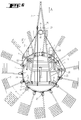
- La figure 1 représente une vue de dessus d'une machine selon l'invention.
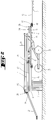
- La figure 2 représente une vue de côté, avec une coupe partielle, de la machine selon l'invention.
- La figure 3 représente une vue de détail d'un bras porte-fourches en position de râtelage.
- La figure 4 représente une vue de détail d'un bras avec les fourches relevées.
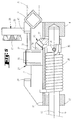
- La figure 5 représente une coupe suivant le plan V-V de la figure 4.
- La figure 6 représente une vue de dessus d'une machine selon un autre exemple de réalisation.
- Figure 1 shows a top view of a machine according to the invention.
- FIG. 2 represents a side view, with a partial section, of the machine according to the invention.
- FIG. 3 represents a detailed view of a fork-carrying arm in the raking position.
- Figure 4 shows a detailed view of an arm with the forks raised.
- FIG. 5 represents a section along the plane VV of FIG. 4.
- FIG. 6 represents a top view of a machine according to another exemplary embodiment.
Telle qu'elle est représentée sur les figures 1 et 2, l'andaineuse selon l'invention comporte un bâti (1) qui peut être accroché à un tracteur, non représenté, au moyen d'un timon (2). Ce bâti (1) est muni de roues porteuses (3) qui roulent sur le sol. Il supporte un rotor d'andainage (4) se composant notamment d'un anneau (5) sur lequel sont montés des bras (6) dirigés vers l'extérieur. Chacun de ces bras (6) porte des fourches (7) à son extrémité extérieure.As shown in Figures 1 and 2, the swather according to the invention comprises a frame (1) which can be hung on a tractor, not shown, by means of a drawbar (2). This frame (1) is provided with supporting wheels (3) which roll on the ground. It supports a swath rotor (4) consisting in particular of a ring (5) on which are mounted arms (6) directed outwards. Each of these arms (6) carries forks (7) at its outer end.
L'anneau (5) est monté sur quatre galets (8) qui sont reliés au bâti (1) et sont disposés dans un plan sensiblement horizontal. Ledit anneau (5) peut tourner sur ces galets (8) autour d'un axe géométrique central (9) qui est vertical ou légèrement incliné par rapport à la verticale. Il ressort notamment de la figure 5 que cet anneau (5) a une section carrée et qu'il est agencé de telle sorte qu'il soit guidé par les galets (8) sur deux de ses côtés. L'anneau (5) porte à intervalles réguliers sur sa périphérie des supports (10) pour les bras porte-fourches (6). Ces supports (10) sont constitués par des plaques avec deux bords (11 et 12) dirigés vers le haut. Ces plaques-supports (10) sont soudées sur l'anneau (5) et portent deux paliers (13 et 14) dans lesquels s'étendent les bras (6). Entre ces bras (6) et lesdits paliers (13 et 14) il est prévu un léger jeu de sorte qu'ils puissent pivoter autour de leurs axes longitudinaux (15) respectifs.The ring (5) is mounted on four rollers (8) which are connected to the frame (1) and are arranged in a substantially horizontal plane. Said ring (5) can rotate on these rollers (8) around a central geometric axis (9) which is vertical or slightly inclined relative to the vertical. It appears in particular from Figure 5 that this ring (5) has a square section and that it is arranged so that it is guided by the rollers (8) on two of its sides. The ring (5) carries at regular intervals on its periphery supports (10) for the fork arms (6). These supports (10) consist of plates with two edges (11 and 12) directed upwards. These support plates (10) are welded to the ring (5) and carry two bearings (13 and 14) in which the arms (6) extend. Between these arms (6) and said bearings (13 and 14) there is a slight clearance so that they can pivot around their respective longitudinal axes (15).
Le rotor (4) comporte par ailleurs un organe de commande (16) des bras porte-fourches (6). Dans l'exemple représenté, cet organe de commande (16) est constitué par une courroie (17). Il pourrait aussi être constitué par une chaîne ou une autre pièce analogue. Cette courroie (17) est guidée au moyen de trois poulies (18, 19 et 20) qui sont montées sur des supports (21, 22 et 23) solidaires du bâti (1) et de pattes (24) verticales solidaires de l'anneau (5). La poulie (18) se situe à l'avant de l'anneau (5), près de l'extrémité la plus avancée du bâti (1). Elle est montée sur un arbre moteur qui peut être entraîné en rotation par exemple à partir de l'arbre de prise de force du tracteur. A cet effet, cet arbre moteur est lié à un carter de renvoi (25) muni d'un second arbre (26) qui peut être relié à l'arbre de prise de force par un arbre de transmission intermédiaire. Les deux poulies (19 et 20) se situent l'une sur le côté gauche et l'autre sur le côté droit du bâti (1). Leurs supports (22 et 23) peuvent être déplacés le long de ce bâti (1) et être fixés en différents endroits.The rotor (4) also comprises a control member (16) of the fork arms (6). In the example shown, this control member (16) is constituted by a belt (17). It could also be constituted by a chain or another similar piece. This belt (17) is guided by means of three pulleys (18, 19 and 20) which are mounted on supports (21, 22 and 23) integral with the frame (1) and vertical tabs (24) integral with the ring (5). The pulley (18) is located at the front of the ring (5), near the most advanced end of the frame (1). It is mounted on a motor shaft which can be driven in rotation for example from the PTO shaft of the tractor. To this end, this drive shaft is linked to a gearbox (25) provided with a second shaft (26) which can be connected to the PTO shaft by an intermediate transmission shaft. The two pulleys (19 and 20) are located one on the left side and the other on the right side of the frame (1). Their supports (22 and 23) can be moved along this frame (1) and be fixed in different places.
La courroie (17) passe sur les pattes (24) de l'anneau (5) sur la partie arrière de celui-ci. Grâce à ce contact avec un grand nombre de ces pattes (24), elle entraîne l'anneau (5) en rotation autour de l'axe géométrique (9) lorsqu'elle est elle-même entraînée par la poulie (18).The belt (17) passes over the tabs (24) of the ring (5) on the rear part of the latter. Thanks to this contact with a large number of these tabs (24), it drives the ring (5) in rotation about the geometric axis (9) when it is itself driven by the pulley (18).
Entre la courroie (17) et chaque bras porte-fourches (6) sont disposés des moyens de transmission (27) qui actionnent lesdits bras (6). Ces moyens (27) sont constitués par une manivelle (28) et un mécanisme de renvoi (29) (voir figure 5). Chaque manivelle (28) se compose d'un levier (30) sensiblement vertical qui se situe au niveau de la courroie (17), d'un bras sensiblement horizontal (31) et d'une douille (32). Cette dernière est montée pivotante sur un axe (33) sensiblement vertical qui est solidaire du support (10) correspondant. La douille (32) comporte un secteur denté (34) qui est orienté vers le bas et qui s'étend sur environ un tiers de sa périphérie. Sur chaque bras porte-fourches (6) est fixée une bague (35) au moyen d'une goupille (36). Cette bague (35) comporte un secteur denté (37) qui est dirigé vers le haut et qui s'étend sur environ un tiers de sa périphérie. Ce secteur (37) engrène avec le secteur (34) précité de la douille (32). Sur chaque bras porte-fourches (6) est en sus monté un ressort de torsion (38). Celui-ci s'appuie d'une part sur la goupille (36) et d'autre part sur le support (10). Il exerce ainsi une pression sur le bras porte-fourches (6) qui tend à le faire pivoter autour de son axe longitudinal (15), de sorte qu'il occupe la position de râtelage représentée sur la figure 3. Le support (10) comporte sur son bord (12) qui est dirigé vers le haut deux butées (39 et 40) qui limitent les déplacements de la manivelle (28). Sur la partie avant (vu dans le sens d'avancement (A)) de l'anneau (5) les manivelles (28) sont plaquées contre les premières butées (39) par les ressorts (38). Ceux-ci agissent sur les bras (6) et, à travers les deux secteurs dentés (37 et 34), sur lesdites manivelles (28). Dans cette position, les fourches (7) des bras (6) sont sensiblement verticales. Sur la partie arrière de l'anneau (5) la courroie (17) est en contact avec les leviers (30) des manivelles (28). Elle déplace ces dernières autour de leurs axes de pivotement (33) et les plaque contre les secondes butées (40). Les secteurs dentés (34 et 37) tournent alors les bras porte-fourches (6) d'environ 90° à l'encontre des ressorts (38), de sorte que les fourches (7) soient sensiblement horizontales. L'exemple de réalisation selon la figure 6 diffère de l'exemple précité en ce que le bâti (1) porte un rail (41) pour le guidage des manivelles (28) sur la partie avant de l'anneau (5). Ce rail (41) est sensiblement parallèle audit anneau (5). Il s'étend à une distance telle de cet anneau (5) qu'il maintient les manivelles (28) en contact avec les premières butées (39). Le rail (41) permet de supprimer les ressorts (38) et assure une plus grande stabilité des bras (6) et des fourches (7) dans la position de râtelage.Between the belt (17) and each fork-carrying arm (6) are arranged transmission means (27) which actuate said arms (6). These means (27) are constituted by a crank (28) and a return mechanism (29) (see Figure 5). Each crank (28) consists of a substantially vertical lever (30) which is located at the level of the belt (17), a substantially horizontal arm (31) and a socket (32). The latter is pivotally mounted on a substantially vertical axis (33) which is integral with the corresponding support (10). The socket (32) has a toothed sector (34) which is oriented downwards and which extends over approximately one third of its periphery. On each fork arm (6) is fixed a ring (35) by means of a pin (36). This ring (35) has a toothed sector (37) which is directed upwards and which extends over approximately one third of its periphery. This sector (37) meshes with the aforementioned sector (34) of the sleeve (32). On each fork arm (6) is additionally mounted a torsion spring (38). This rests on the one hand on the pin (36) and on the other hand on the support (10). It thus exerts pressure on the fork-carrying arm (6) which tends to pivot it around its longitudinal axis (15), so that it occupies the raking position shown in FIG. 3. The support (10) has on its edge (12) which is directed upwards two stops (39 and 40) which limit the movements of the crank (28). On the front part (seen in the direction of advance (A)) of the ring (5) the cranks (28) are pressed against the first stops (39) by the springs (38). These act on the arms (6) and, through the two toothed sectors (37 and 34), on said cranks (28). In this position, the forks (7) of the arms (6) are substantially vertical. On the rear part of the ring (5) the belt (17) is in contact with the levers (30) of the cranks (28). It moves the latter around their pivot axes (33) and presses them against the second stops (40). The toothed sectors (34 and 37) then rotate the fork arms (6) by approximately 90 ° against the springs (38), so that the forks (7) are substantially horizontal. The embodiment according to FIG. 6 differs from the above example in that the frame (1) carries a rail (41) for guiding the cranks (28) on the front part of the ring (5). This rail (41) is substantially parallel to said ring (5). It extends at such a distance from this ring (5) that it keeps the cranks (28) in contact with the first stops (39). The rail (41) eliminates the springs (38) and ensures greater stability of the arms (6) and forks (7) in the raking position.
Durant le travail, la machine selon l'invention est déplacée selon l'invention dans la direction d'avancement (A) au moyen du tracteur. La courroie (17) est entraînée dans le sens de la flèche (F) par la poulie (18). Elle entraîne alors l'anneau (5) avec les bras porte-fourches (6) dans le même sens de sorte qu'il tourne sur les galets (8) autour de l'axe géométrique (9). Durant cette rotation, les bras porte-fourches (6) qui se situent sur la partie avant de l'anneau (5) ratissent les végétaux qui se trouvent au sol. Lorsqu'ils arrivent dans la partie latérale de l'anneau (5), leurs manivelles (28) entrent en contact avec la courroie (17). Celle-ci déplace alors ces manivelles (28) sur leurs axes (33) jusqu'à ce qu'elles rencontrent les secondes butées (40). Lors de ces déplacements, les secteurs dentés (34 et 37) font pivoter les bras porte-fourches (6) autour de leurs axes longitudinaux (15). Dans l'exemple selon les figures 1 à 5 ces pivotements s'effectuent à l'encontre de la force des ressorts (38). Les fourches (7) sont alors relevées à l'horizontale, de sorte qu'elles déposent les végétaux ratissés sous la forme d'un andain (figure 4). Ces fourches (7) restent dans la position relevée sur toute la partie arrière de l'anneau (5). Ensuite, la courroie (17) est guidée par la poulie (20) de sorte qu'elle s'éloigne de l'anneau (5) et libère les manivelles (28). Simultanément, les ressorts (38) font pivoter les bras (6) autour de leurs axes longitudinaux (15). Lesdits bras (6) entraînent les manivelles (28) correspondantes par l'intermédiaire des secteurs dentés (37 et 34) jusqu'à ce qu'elles rencontrent les premières butées (39). Dans cette position, les fourches (7) se situent à nouveau dans la position de ratissage (figure 3). Dans l'exemple selon la figure 6 c'est le rail (41) qui fait pivoter les manivelles (28) de telle sorte qu'elles fassent pivoter les bras (6) et les fourches (7) dans la position de ratissage.During work, the machine according to the invention is moved according to the invention in the direction of advance (A) by means of the tractor. The belt (17) is driven in the direction of the arrow (F) by the pulley (18). It then drives the ring (5) with the fork arms (6) in the same direction so that it rotates on the rollers (8) around the geometric axis (9). During this rotation, the fork arms (6) which are located on the front part of the ring (5) rake the plants which are on the ground. When they arrive in the lateral part of the ring (5), their cranks (28) come into contact with the belt (17). The latter then moves these cranks (28) on their axes (33) until they meet the second stops (40). During these movements, the toothed sectors (34 and 37) pivot the fork-carrying arms (6) around their longitudinal axes (15). In the example according to FIGS. 1 to 5, these pivotings take place against the force of the springs (38). The forks (7) are then raised horizontally, so that they deposit the raked plants in the form of a swath (Figure 4). These forks (7) remain in the raised position over the entire rear part of the ring (5). Then, the belt (17) is guided by the pulley (20) so that it moves away from the ring (5) and releases the cranks (28). Simultaneously, the springs (38) rotate the arms (6) about their longitudinal axes (15). Said arms (6) drive the corresponding cranks (28) via the toothed sectors (37 and 34) until they meet the first stops (39). In this position, the forks (7) are again in the raking position (Figure 3). In the example according to figure 6 it is the rail (41) which rotates the cranks (28) so that they rotate the arms (6) and the forks (7) in the raking position.
Il est bien évident que l'invention n'est pas limitée aux modes de réalisation décrits et représentés sur les dessins annexés. Des modifications sont possibles, notamment en ce qui concerne la constitution des divers éléments ou par substitution d'équivalents techniques, sans pour autant sortir du domaine de protection tel que défini dans les revendications.It is obvious that the invention is not limited to the embodiments described and shown in the accompanying drawings. Modifications are possible, in particular as regards the constitution of the various elements or by substitution of technical equivalents, without however departing from the field of protection as defined in the claims.
Claims (11)
Applications Claiming Priority (2)
| Application Number | Priority Date | Filing Date | Title |
|---|---|---|---|
| FR9408880A FR2722364B1 (en) | 1994-07-13 | 1994-07-13 | FENAISON MACHINE, PARTICULARLY A PLANT SWATHER WITH A PERFECTED CONTROL ARM OF FORK ARMS |
| FR9408880 | 1994-07-13 |
Publications (2)
| Publication Number | Publication Date |
|---|---|
| EP0692184A1 true EP0692184A1 (en) | 1996-01-17 |
| EP0692184B1 EP0692184B1 (en) | 2001-01-10 |
Family
ID=9465496
Family Applications (1)
| Application Number | Title | Priority Date | Filing Date |
|---|---|---|---|
| EP95440040A Expired - Lifetime EP0692184B1 (en) | 1994-07-13 | 1995-07-04 | Haymaking machine, especially a swather, with an improved control member for the fork-carrying arms |
Country Status (4)
| Country | Link |
|---|---|
| EP (1) | EP0692184B1 (en) |
| AT (1) | ATE198526T1 (en) |
| DE (1) | DE69519828T2 (en) |
| FR (1) | FR2722364B1 (en) |
Cited By (1)
| Publication number | Priority date | Publication date | Assignee | Title |
|---|---|---|---|---|
| CN105474886A (en) * | 2016-01-18 | 2016-04-13 | 中外合资沃得重工(中国)有限公司 | Two-freedom-degree pasture raking arm driving device |
Citations (6)
| Publication number | Priority date | Publication date | Assignee | Title |
|---|---|---|---|---|
| GB1118682A (en) * | 1964-07-17 | 1968-07-03 | Fr Vandenabeele Sa Ets | Haymaking machine |
| FR1589179A (en) | 1967-09-28 | 1970-03-23 | ||
| CH490786A (en) * | 1968-05-27 | 1970-05-31 | Bucher Guyer Ag Masch | Haymaking machine |
| GB1220337A (en) * | 1966-12-23 | 1971-01-27 | Texas Industries Inc | Improvements in or relating to hay-making machines |
| FR2095608A5 (en) * | 1970-06-03 | 1972-02-11 | Fahr Ag Maschf | |
| DE2150555A1 (en) * | 1971-10-11 | 1973-04-19 | Strautmann & Soehne | HAYMAKING MACHINE |
-
1994
- 1994-07-13 FR FR9408880A patent/FR2722364B1/en not_active Expired - Fee Related
-
1995
- 1995-07-04 EP EP95440040A patent/EP0692184B1/en not_active Expired - Lifetime
- 1995-07-04 DE DE69519828T patent/DE69519828T2/en not_active Expired - Fee Related
- 1995-07-04 AT AT95440040T patent/ATE198526T1/en not_active IP Right Cessation
Patent Citations (6)
| Publication number | Priority date | Publication date | Assignee | Title |
|---|---|---|---|---|
| GB1118682A (en) * | 1964-07-17 | 1968-07-03 | Fr Vandenabeele Sa Ets | Haymaking machine |
| GB1220337A (en) * | 1966-12-23 | 1971-01-27 | Texas Industries Inc | Improvements in or relating to hay-making machines |
| FR1589179A (en) | 1967-09-28 | 1970-03-23 | ||
| CH490786A (en) * | 1968-05-27 | 1970-05-31 | Bucher Guyer Ag Masch | Haymaking machine |
| FR2095608A5 (en) * | 1970-06-03 | 1972-02-11 | Fahr Ag Maschf | |
| DE2150555A1 (en) * | 1971-10-11 | 1973-04-19 | Strautmann & Soehne | HAYMAKING MACHINE |
Cited By (1)
| Publication number | Priority date | Publication date | Assignee | Title |
|---|---|---|---|---|
| CN105474886A (en) * | 2016-01-18 | 2016-04-13 | 中外合资沃得重工(中国)有限公司 | Two-freedom-degree pasture raking arm driving device |
Also Published As
| Publication number | Publication date |
|---|---|
| FR2722364A1 (en) | 1996-01-19 |
| DE69519828T2 (en) | 2001-07-12 |
| ATE198526T1 (en) | 2001-01-15 |
| FR2722364B1 (en) | 1996-09-20 |
| EP0692184B1 (en) | 2001-01-10 |
| DE69519828D1 (en) | 2001-02-15 |
Similar Documents
| Publication | Publication Date | Title |
|---|---|---|
| EP0332552B1 (en) | Improvement for agricultural harvesting machines | |
| EP0408090B1 (en) | Rotary mower | |
| EP2253186B1 (en) | Haymaking machine | |
| FR2628596A1 (en) | MACHINE WITH DIRECT DRIVE | |
| FR2754136A1 (en) | HUNTING MACHINE COMPRISING A CHASSIS COMPRISING SEVERAL ARTICULATED TRUNCTIONS BETWEEN THEM | |
| FR2663189A1 (en) | Haymaking machine for windrowing, including at least two raking (tedding) wheels | |
| EP0390713B1 (en) | Agricultural machine having at least one rotor for moving products located on the ground | |
| EP1290936B1 (en) | Haymaking machine | |
| EP0692185B1 (en) | Haymaking machine, especially a swather with controlled fork-carrying arms | |
| EP0285537A1 (en) | Hay making machine | |
| EP0772969B1 (en) | Haymaking machine with at least one windrowing rotor | |
| EP0614604B1 (en) | Hay-making machine | |
| EP0514302B1 (en) | Improved crop windrower | |
| EP0954956B1 (en) | Haymaking machine | |
| EP0680688B1 (en) | Haymaking machine, especially a forage windrower | |
| EP0692184B1 (en) | Haymaking machine, especially a swather, with an improved control member for the fork-carrying arms | |
| EP0554200B1 (en) | Haymaking machine comprising a frame with controlled support wheels | |
| FR2707450A1 (en) | Hay-making machine with tedding or windrowing rotors equipped with wheels for resting on the ground | |
| EP0135459A1 (en) | Disc mower | |
| EP0654209B1 (en) | Haymaking machine | |
| EP1269826B1 (en) | Haymaking machine | |
| FR2759245A1 (en) | FENAISON MACHINE WITH A GROUND SUPPORT DEVICE INCLUDING AT LEAST A BALANCER WITH TWO CARRIER WHEELS AND A MEANS FOR MOVING THIS BALANCER FOR TRANSPORT | |
| EP0772970B1 (en) | Haymaking machine, especially a tedder | |
| EP0655188B1 (en) | Hay making machine | |
| FR2798817A1 (en) | Swathing machine, for hay making, consists of primary and secondary beams with rotors, with rotors supported by wheels mounted on transverse beams carried by support axis mounted beneath swathing rotors |
Legal Events
| Date | Code | Title | Description |
|---|---|---|---|
| PUAI | Public reference made under article 153(3) epc to a published international application that has entered the european phase |
Free format text: ORIGINAL CODE: 0009012 |
|
| AK | Designated contracting states |
Kind code of ref document: A1 Designated state(s): AT DE DK FR IT NL |
|
| 17P | Request for examination filed |
Effective date: 19960624 |
|
| 17Q | First examination report despatched |
Effective date: 19990318 |
|
| GRAG | Despatch of communication of intention to grant |
Free format text: ORIGINAL CODE: EPIDOS AGRA |
|
| GRAG | Despatch of communication of intention to grant |
Free format text: ORIGINAL CODE: EPIDOS AGRA |
|
| GRAH | Despatch of communication of intention to grant a patent |
Free format text: ORIGINAL CODE: EPIDOS IGRA |
|
| GRAH | Despatch of communication of intention to grant a patent |
Free format text: ORIGINAL CODE: EPIDOS IGRA |
|
| GRAA | (expected) grant |
Free format text: ORIGINAL CODE: 0009210 |
|
| AK | Designated contracting states |
Kind code of ref document: B1 Designated state(s): AT DE DK FR IT NL |
|
| PG25 | Lapsed in a contracting state [announced via postgrant information from national office to epo] |
Ref country code: NL Free format text: LAPSE BECAUSE OF FAILURE TO SUBMIT A TRANSLATION OF THE DESCRIPTION OR TO PAY THE FEE WITHIN THE PRESCRIBED TIME-LIMIT Effective date: 20010110 Ref country code: IT Free format text: LAPSE BECAUSE OF FAILURE TO SUBMIT A TRANSLATION OF THE DESCRIPTION OR TO PAY THE FEE WITHIN THE PRESCRIBED TIME-LIMIT;WARNING: LAPSES OF ITALIAN PATENTS WITH EFFECTIVE DATE BEFORE 2007 MAY HAVE OCCURRED AT ANY TIME BEFORE 2007. THE CORRECT EFFECTIVE DATE MAY BE DIFFERENT FROM THE ONE RECORDED. Effective date: 20010110 |
|
| REF | Corresponds to: |
Ref document number: 198526 Country of ref document: AT Date of ref document: 20010115 Kind code of ref document: T |
|
| REF | Corresponds to: |
Ref document number: 69519828 Country of ref document: DE Date of ref document: 20010215 |
|
| PG25 | Lapsed in a contracting state [announced via postgrant information from national office to epo] |
Ref country code: DK Free format text: LAPSE BECAUSE OF FAILURE TO SUBMIT A TRANSLATION OF THE DESCRIPTION OR TO PAY THE FEE WITHIN THE PRESCRIBED TIME-LIMIT Effective date: 20010410 |
|
| NLV1 | Nl: lapsed or annulled due to failure to fulfill the requirements of art. 29p and 29m of the patents act | ||
| PLBE | No opposition filed within time limit |
Free format text: ORIGINAL CODE: 0009261 |
|
| STAA | Information on the status of an ep patent application or granted ep patent |
Free format text: STATUS: NO OPPOSITION FILED WITHIN TIME LIMIT |
|
| 26N | No opposition filed | ||
| PGFP | Annual fee paid to national office [announced via postgrant information from national office to epo] |
Ref country code: AT Payment date: 20040624 Year of fee payment: 10 |
|
| PGFP | Annual fee paid to national office [announced via postgrant information from national office to epo] |
Ref country code: DE Payment date: 20040629 Year of fee payment: 10 |
|
| PG25 | Lapsed in a contracting state [announced via postgrant information from national office to epo] |
Ref country code: AT Free format text: LAPSE BECAUSE OF NON-PAYMENT OF DUE FEES Effective date: 20050704 |
|
| PG25 | Lapsed in a contracting state [announced via postgrant information from national office to epo] |
Ref country code: DE Free format text: LAPSE BECAUSE OF NON-PAYMENT OF DUE FEES Effective date: 20060201 |
|
| PGFP | Annual fee paid to national office [announced via postgrant information from national office to epo] |
Ref country code: FR Payment date: 20140721 Year of fee payment: 20 |