EP0692184A1 - Heuwerbungsmaschine, namentlich ein Schwader, mit einem verbesserten Steuerorgan der Zinkentragarme - Google Patents
Heuwerbungsmaschine, namentlich ein Schwader, mit einem verbesserten Steuerorgan der Zinkentragarme Download PDFInfo
- Publication number
- EP0692184A1 EP0692184A1 EP95440040A EP95440040A EP0692184A1 EP 0692184 A1 EP0692184 A1 EP 0692184A1 EP 95440040 A EP95440040 A EP 95440040A EP 95440040 A EP95440040 A EP 95440040A EP 0692184 A1 EP0692184 A1 EP 0692184A1
- Authority
- EP
- European Patent Office
- Prior art keywords
- fork
- machine according
- belt
- rotor
- crank
- Prior art date
- Legal status (The legal status is an assumption and is not a legal conclusion. Google has not performed a legal analysis and makes no representation as to the accuracy of the status listed.)
- Granted
Links
Images


Classifications
-
- A—HUMAN NECESSITIES
- A01—AGRICULTURE; FORESTRY; ANIMAL HUSBANDRY; HUNTING; TRAPPING; FISHING
- A01D—HARVESTING; MOWING
- A01D78/00—Haymakers with tines moving with respect to the machine
- A01D78/08—Haymakers with tines moving with respect to the machine with tine-carrying rotary heads or wheels
- A01D78/10—Haymakers with tines moving with respect to the machine with tine-carrying rotary heads or wheels the tines rotating about a substantially vertical axis
- A01D78/12—Haymakers with tines moving with respect to the machine with tine-carrying rotary heads or wheels the tines rotating about a substantially vertical axis the tines having an additional movement superimposed upon their rotary movement
Definitions
- the present invention relates to a haymaking machine, in particular a plant swather, comprising a frame which can be hung on a tractor and which is provided with carrying wheels, which frame supports at least one swath rotor driven in rotation around '' a vertical or slightly inclined axis with respect to the vertical and carrying fork arms which are pivotally mounted in bearings and which are actuated by a control member and transmission means, so that they pivot around their respective longitudinal axes during work.
- Known machines of this kind generally comprise a control member constituted by a fixed central cam mounted on a central support axis of the rotor (Patent FR 1,589,179).
- This cam move rollers which are mounted on levers integral with the fork arms.
- This cam has a drop which causes a displacement in height of the rollers during each revolution.
- the levers on which these rollers are mounted then pivot the fork arms around their respective longitudinal axes, so that the forks are substantially vertical in the front part of their trajectory and pick up the plants which are on the ground and that 'they rise in the lateral part of their trajectory and deposit the plants in the form of a swath.
- Machines equipped with a rotor with such a control cam are limited as regards their working width.
- the fork arms cannot be extended too much due to the overhang and the significant stresses which would be exerted on their support bearings, their rollers and the control cam.
- the diameter of this cam can be increased significantly so as not to make the rotor too heavy.
- the friction between the rollers of the fork arms and the control cam more or less rapidly increases the clearance between these parts, which results in an impairment of the control of the fork arms.
- the object of the present invention is to propose a haymaking machine which does not have these drawbacks.
- an important characteristic of the invention consists in that the control member of the fork-carrying arms consists of a belt or the like which rotates with the rotor and that the transmission means for actuating each carrying arm -forks consist of a crank movable by means of the belt and a return mechanism between said crank and the corresponding fork-carrying arm.
- the control belt which is linked to the rotor and not to a central support axis, can be located over a large diameter.
- the fork arms need no longer extend close to the center of the rotor. It is thus possible to obtain a large working width with relatively short fork arms. This also makes it possible to equip the rotor with a greater number of fork-carrying arms so that they ensure correct raking of all the plants even when the forward speed is high.
- this control belt is relatively lighter than a guide cam fixed to a central axis of the rotor. This is particularly advantageous in the case of a large width rotor which would require a cam with a large diameter. This belt is also subjected to less friction than a fixed cam in which rollers move. It therefore constantly ensures perfect control of the fork arms.
- control belt additionally ensures the rotational drive of the rotor. This makes it possible to avoid the use of additional means specially intended for said training.
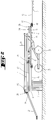
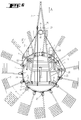
- the swather according to the invention comprises a frame (1) which can be hung on a tractor, not shown, by means of a drawbar (2).
- This frame (1) is provided with supporting wheels (3) which roll on the ground. It supports a swath rotor (4) consisting in particular of a ring (5) on which are mounted arms (6) directed outwards. Each of these arms (6) carries forks (7) at its outer end.
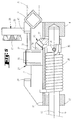
- the ring (5) is mounted on four rollers (8) which are connected to the frame (1) and are arranged in a substantially horizontal plane. Said ring (5) can rotate on these rollers (8) around a central geometric axis (9) which is vertical or slightly inclined relative to the vertical. It appears in particular from Figure 5 that this ring (5) has a square section and that it is arranged so that it is guided by the rollers (8) on two of its sides.
- the ring (5) carries at regular intervals on its periphery supports (10) for the fork arms (6). These supports (10) consist of plates with two edges (11 and 12) directed upwards. These support plates (10) are welded to the ring (5) and carry two bearings (13 and 14) in which the arms (6) extend. Between these arms (6) and said bearings (13 and 14) there is a slight clearance so that they can pivot around their respective longitudinal axes (15).
- the rotor (4) also comprises a control member (16) of the fork arms (6).
- this control member (16) is constituted by a belt (17). It could also be constituted by a chain or another similar piece.
- This belt (17) is guided by means of three pulleys (18, 19 and 20) which are mounted on supports (21, 22 and 23) integral with the frame (1) and vertical tabs (24) integral with the ring (5).
- the pulley (18) is located at the front of the ring (5), near the most advanced end of the frame (1). It is mounted on a motor shaft which can be driven in rotation for example from the PTO shaft of the tractor.
- this drive shaft is linked to a gearbox (25) provided with a second shaft (26) which can be connected to the PTO shaft by an intermediate transmission shaft.
- the two pulleys (19 and 20) are located one on the left side and the other on the right side of the frame (1). Their supports (22 and 23) can be moved along this frame (1) and be fixed in different places.
- the belt (17) passes over the tabs (24) of the ring (5) on the rear part of the latter. Thanks to this contact with a large number of these tabs (24), it drives the ring (5) in rotation about the geometric axis (9) when it is itself driven by the pulley (18).
- transmission means (27) which actuate said arms (6).
- These means (27) are constituted by a crank (28) and a return mechanism (29) (see Figure 5).
- Each crank (28) consists of a substantially vertical lever (30) which is located at the level of the belt (17), a substantially horizontal arm (31) and a socket (32). The latter is pivotally mounted on a substantially vertical axis (33) which is integral with the corresponding support (10).
- the socket (32) has a toothed sector (34) which is oriented downwards and which extends over approximately one third of its periphery.
- On each fork arm (6) is fixed a ring (35) by means of a pin (36).
- This ring (35) has a toothed sector (37) which is directed upwards and which extends over approximately one third of its periphery. This sector (37) meshes with the aforementioned sector (34) of the sleeve (32).
- On each fork arm (6) is additionally mounted a torsion spring (38). This rests on the one hand on the pin (36) and on the other hand on the support (10). It thus exerts pressure on the fork-carrying arm (6) which tends to pivot it around its longitudinal axis (15), so that it occupies the raking position shown in FIG. 3.
- the support (10) has on its edge (12) which is directed upwards two stops (39 and 40) which limit the movements of the crank (28).
- the frame (1) carries a rail (41) for guiding the cranks (28) on the front part of the ring (5).
- This rail (41) is substantially parallel to said ring (5). It extends at such a distance from this ring (5) that it keeps the cranks (28) in contact with the first stops (39).
- the rail (41) eliminates the springs (38) and ensures greater stability of the arms (6) and forks (7) in the raking position.
- the machine according to the invention is moved according to the invention in the direction of advance (A) by means of the tractor.
- the belt (17) is driven in the direction of the arrow (F) by the pulley (18). It then drives the ring (5) with the fork arms (6) in the same direction so that it rotates on the rollers (8) around the geometric axis (9).
- the fork arms (6) which are located on the front part of the ring (5) rake the plants which are on the ground.
- their cranks (28) come into contact with the belt (17).
- the latter then moves these cranks (28) on their axes (33) until they meet the second stops (40).
- the toothed sectors (34 and 37) pivot the fork-carrying arms (6) around their longitudinal axes (15).
- these pivotings take place against the force of the springs (38).
- the forks (7) are then raised horizontally, so that they deposit the raked plants in the form of a swath ( Figure 4).
- These forks (7) remain in the raised position over the entire rear part of the ring (5).
- the belt (17) is guided by the pulley (20) so that it moves away from the ring (5) and releases the cranks (28).
- the springs (38) rotate the arms (6) about their longitudinal axes (15).
Landscapes
- Life Sciences & Earth Sciences (AREA)
- Environmental Sciences (AREA)
- Agricultural Machines (AREA)
- Outside Dividers And Delivering Mechanisms For Harvesters (AREA)
- Soil Working Implements (AREA)
- Discharge By Other Means (AREA)
- Forklifts And Lifting Vehicles (AREA)
- Manipulator (AREA)
- Load-Engaging Elements For Cranes (AREA)
Applications Claiming Priority (2)
| Application Number | Priority Date | Filing Date | Title |
|---|---|---|---|
| FR9408880 | 1994-07-13 | ||
| FR9408880A FR2722364B1 (fr) | 1994-07-13 | 1994-07-13 | Machine de fenaison, notamment une andaineuse de vegetaux avex un organe de commande perfectionne des bras porte-fourches |
Publications (2)
| Publication Number | Publication Date |
|---|---|
| EP0692184A1 true EP0692184A1 (de) | 1996-01-17 |
| EP0692184B1 EP0692184B1 (de) | 2001-01-10 |
Family
ID=9465496
Family Applications (1)
| Application Number | Title | Priority Date | Filing Date |
|---|---|---|---|
| EP95440040A Expired - Lifetime EP0692184B1 (de) | 1994-07-13 | 1995-07-04 | Heuwerbungsmaschine, namentlich ein Schwader, mit einem verbesserten Steuerorgan der Zinkentragarme |
Country Status (4)
| Country | Link |
|---|---|
| EP (1) | EP0692184B1 (de) |
| AT (1) | ATE198526T1 (de) |
| DE (1) | DE69519828T2 (de) |
| FR (1) | FR2722364B1 (de) |
Cited By (1)
| Publication number | Priority date | Publication date | Assignee | Title |
|---|---|---|---|---|
| CN105474886A (zh) * | 2016-01-18 | 2016-04-13 | 中外合资沃得重工(中国)有限公司 | 二自由度搂草臂驱动装置 |
Citations (6)
| Publication number | Priority date | Publication date | Assignee | Title |
|---|---|---|---|---|
| GB1118682A (en) * | 1964-07-17 | 1968-07-03 | Fr Vandenabeele Sa Ets | Haymaking machine |
| FR1589179A (de) | 1967-09-28 | 1970-03-23 | ||
| CH490786A (de) * | 1968-05-27 | 1970-05-31 | Bucher Guyer Ag Masch | Heuerntemaschine |
| GB1220337A (en) * | 1966-12-23 | 1971-01-27 | Texas Industries Inc | Improvements in or relating to hay-making machines |
| FR2095608A5 (de) * | 1970-06-03 | 1972-02-11 | Fahr Ag Maschf | |
| DE2150555A1 (de) * | 1971-10-11 | 1973-04-19 | Strautmann & Soehne | Heuwerbungsmaschine |
-
1994
- 1994-07-13 FR FR9408880A patent/FR2722364B1/fr not_active Expired - Fee Related
-
1995
- 1995-07-04 DE DE69519828T patent/DE69519828T2/de not_active Expired - Fee Related
- 1995-07-04 EP EP95440040A patent/EP0692184B1/de not_active Expired - Lifetime
- 1995-07-04 AT AT95440040T patent/ATE198526T1/de not_active IP Right Cessation
Patent Citations (6)
| Publication number | Priority date | Publication date | Assignee | Title |
|---|---|---|---|---|
| GB1118682A (en) * | 1964-07-17 | 1968-07-03 | Fr Vandenabeele Sa Ets | Haymaking machine |
| GB1220337A (en) * | 1966-12-23 | 1971-01-27 | Texas Industries Inc | Improvements in or relating to hay-making machines |
| FR1589179A (de) | 1967-09-28 | 1970-03-23 | ||
| CH490786A (de) * | 1968-05-27 | 1970-05-31 | Bucher Guyer Ag Masch | Heuerntemaschine |
| FR2095608A5 (de) * | 1970-06-03 | 1972-02-11 | Fahr Ag Maschf | |
| DE2150555A1 (de) * | 1971-10-11 | 1973-04-19 | Strautmann & Soehne | Heuwerbungsmaschine |
Cited By (1)
| Publication number | Priority date | Publication date | Assignee | Title |
|---|---|---|---|---|
| CN105474886A (zh) * | 2016-01-18 | 2016-04-13 | 中外合资沃得重工(中国)有限公司 | 二自由度搂草臂驱动装置 |
Also Published As
| Publication number | Publication date |
|---|---|
| FR2722364B1 (fr) | 1996-09-20 |
| DE69519828D1 (de) | 2001-02-15 |
| EP0692184B1 (de) | 2001-01-10 |
| DE69519828T2 (de) | 2001-07-12 |
| ATE198526T1 (de) | 2001-01-15 |
| FR2722364A1 (fr) | 1996-01-19 |
Similar Documents
| Publication | Publication Date | Title |
|---|---|---|
| EP0332552B1 (de) | Verbesserung an Landmaschinen für die Futterernte | |
| EP0408090B1 (de) | Kreiselmäher | |
| EP2253186B1 (de) | Heuwerbungsmaschine | |
| FR2628596A1 (fr) | Faucheuse a entrainement direct | |
| FR2754136A1 (fr) | Machine de fenaison comportant un chassis compose de plusieurs troncons articules entre eux | |
| FR2663189A1 (fr) | Machine de fenaison pour l'andainage, comportant au moins deux roues rateleuses. | |
| EP0390713B1 (de) | Landmaschine mit mindestens einem Rechrad zum Versetzen von sich auf dem Boden befindlichen Produkten | |
| EP1290936B1 (de) | Heuwerbungsmaschine | |
| EP0692185B1 (de) | Heuwerbungsmaschine, namentlich ein Schwader mit gesteuerten Zinkentragarmen | |
| EP0285537A1 (de) | Heuerntemaschine | |
| EP0772969B1 (de) | Heuwerbungsmaschine mit mindestens einem Rotor zum Schwaden | |
| EP0614604B1 (de) | Heuwerbungsmaschine | |
| EP0514302B1 (de) | Verbesserter Pflanzenschwader | |
| EP0954956B1 (de) | Heuwerbungsmaschine | |
| EP0680688B1 (de) | Heuwerbungsmaschine, insbesondere ein Schwader für Futter | |
| EP0692184B1 (de) | Heuwerbungsmaschine, namentlich ein Schwader, mit einem verbesserten Steuerorgan der Zinkentragarme | |
| EP0554200B1 (de) | Heuwerbungsmaschine mit einem mit gesteuerten Stützrädern versehenen Rahmen | |
| FR2707450A1 (fr) | Machine de fenaison avec des rotors de fanage ou d'andainage munis de roues d'appui au sol. | |
| EP0135459A1 (de) | Scheibenmäher | |
| EP0654209B1 (de) | Heuwerbungsmaschine | |
| EP1269826B1 (de) | Heuwerbungsmaschine | |
| FR2759245A1 (fr) | Machine de fenaison avec un dispositif d'appui au sol incluant au moins un balancier avec deux roues porteuses et un moyen pour deplacer ce balancier en vue du transport | |
| EP0772970B1 (de) | Heuwerbungsmaschine, insbesondere ein Zett-Wender | |
| EP0655188B1 (de) | Heuwerbungsmaschine | |
| FR2798817A1 (fr) | Machine de fenaison, notamment une andaineuse avec plusieurs rotors s'appuyant sur le sol au moyen de roues porteuses |
Legal Events
| Date | Code | Title | Description |
|---|---|---|---|
| PUAI | Public reference made under article 153(3) epc to a published international application that has entered the european phase |
Free format text: ORIGINAL CODE: 0009012 |
|
| AK | Designated contracting states |
Kind code of ref document: A1 Designated state(s): AT DE DK FR IT NL |
|
| 17P | Request for examination filed |
Effective date: 19960624 |
|
| 17Q | First examination report despatched |
Effective date: 19990318 |
|
| GRAG | Despatch of communication of intention to grant |
Free format text: ORIGINAL CODE: EPIDOS AGRA |
|
| GRAG | Despatch of communication of intention to grant |
Free format text: ORIGINAL CODE: EPIDOS AGRA |
|
| GRAH | Despatch of communication of intention to grant a patent |
Free format text: ORIGINAL CODE: EPIDOS IGRA |
|
| GRAH | Despatch of communication of intention to grant a patent |
Free format text: ORIGINAL CODE: EPIDOS IGRA |
|
| GRAA | (expected) grant |
Free format text: ORIGINAL CODE: 0009210 |
|
| AK | Designated contracting states |
Kind code of ref document: B1 Designated state(s): AT DE DK FR IT NL |
|
| PG25 | Lapsed in a contracting state [announced via postgrant information from national office to epo] |
Ref country code: NL Free format text: LAPSE BECAUSE OF FAILURE TO SUBMIT A TRANSLATION OF THE DESCRIPTION OR TO PAY THE FEE WITHIN THE PRESCRIBED TIME-LIMIT Effective date: 20010110 Ref country code: IT Free format text: LAPSE BECAUSE OF FAILURE TO SUBMIT A TRANSLATION OF THE DESCRIPTION OR TO PAY THE FEE WITHIN THE PRESCRIBED TIME-LIMIT;WARNING: LAPSES OF ITALIAN PATENTS WITH EFFECTIVE DATE BEFORE 2007 MAY HAVE OCCURRED AT ANY TIME BEFORE 2007. THE CORRECT EFFECTIVE DATE MAY BE DIFFERENT FROM THE ONE RECORDED. Effective date: 20010110 |
|
| REF | Corresponds to: |
Ref document number: 198526 Country of ref document: AT Date of ref document: 20010115 Kind code of ref document: T |
|
| REF | Corresponds to: |
Ref document number: 69519828 Country of ref document: DE Date of ref document: 20010215 |
|
| PG25 | Lapsed in a contracting state [announced via postgrant information from national office to epo] |
Ref country code: DK Free format text: LAPSE BECAUSE OF FAILURE TO SUBMIT A TRANSLATION OF THE DESCRIPTION OR TO PAY THE FEE WITHIN THE PRESCRIBED TIME-LIMIT Effective date: 20010410 |
|
| NLV1 | Nl: lapsed or annulled due to failure to fulfill the requirements of art. 29p and 29m of the patents act | ||
| PLBE | No opposition filed within time limit |
Free format text: ORIGINAL CODE: 0009261 |
|
| STAA | Information on the status of an ep patent application or granted ep patent |
Free format text: STATUS: NO OPPOSITION FILED WITHIN TIME LIMIT |
|
| 26N | No opposition filed | ||
| PGFP | Annual fee paid to national office [announced via postgrant information from national office to epo] |
Ref country code: AT Payment date: 20040624 Year of fee payment: 10 |
|
| PGFP | Annual fee paid to national office [announced via postgrant information from national office to epo] |
Ref country code: DE Payment date: 20040629 Year of fee payment: 10 |
|
| PG25 | Lapsed in a contracting state [announced via postgrant information from national office to epo] |
Ref country code: AT Free format text: LAPSE BECAUSE OF NON-PAYMENT OF DUE FEES Effective date: 20050704 |
|
| PG25 | Lapsed in a contracting state [announced via postgrant information from national office to epo] |
Ref country code: DE Free format text: LAPSE BECAUSE OF NON-PAYMENT OF DUE FEES Effective date: 20060201 |
|
| PGFP | Annual fee paid to national office [announced via postgrant information from national office to epo] |
Ref country code: FR Payment date: 20140721 Year of fee payment: 20 |