EP1290936B1 - Heuwerbungsmaschine - Google Patents
Heuwerbungsmaschine Download PDFInfo
- Publication number
- EP1290936B1 EP1290936B1 EP02360258A EP02360258A EP1290936B1 EP 1290936 B1 EP1290936 B1 EP 1290936B1 EP 02360258 A EP02360258 A EP 02360258A EP 02360258 A EP02360258 A EP 02360258A EP 1290936 B1 EP1290936 B1 EP 1290936B1
- Authority
- EP
- European Patent Office
- Prior art keywords
- machine
- telescopic
- axis
- telescopic part
- carrier arm
- Prior art date
- Legal status (The legal status is an assumption and is not a legal conclusion. Google has not performed a legal analysis and makes no representation as to the accuracy of the status listed.)
- Expired - Lifetime
Links
- 239000004459 forage Substances 0.000 claims description 6
- 238000006073 displacement reaction Methods 0.000 description 2
- 244000025254 Cannabis sativa Species 0.000 description 1
- 241001124569 Lycaenidae Species 0.000 description 1
- 238000010276 construction Methods 0.000 description 1
- 230000008878 coupling Effects 0.000 description 1
- 238000010168 coupling process Methods 0.000 description 1
- 238000005859 coupling reaction Methods 0.000 description 1
- 238000012986 modification Methods 0.000 description 1
- 230000004048 modification Effects 0.000 description 1
- 238000004904 shortening Methods 0.000 description 1
- 239000010902 straw Substances 0.000 description 1
- 238000006467 substitution reaction Methods 0.000 description 1
Images
Classifications
-
- A—HUMAN NECESSITIES
- A01—AGRICULTURE; FORESTRY; ANIMAL HUSBANDRY; HUNTING; TRAPPING; FISHING
- A01D—HARVESTING; MOWING
- A01D78/00—Haymakers with tines moving with respect to the machine
- A01D78/08—Haymakers with tines moving with respect to the machine with tine-carrying rotary heads or wheels
- A01D78/10—Haymakers with tines moving with respect to the machine with tine-carrying rotary heads or wheels the tines rotating about a substantially vertical axis
- A01D78/1085—Having two rows of rotors on two different horizontal lines perpendicular to the advance direction of the machine
-
- A—HUMAN NECESSITIES
- A01—AGRICULTURE; FORESTRY; ANIMAL HUSBANDRY; HUNTING; TRAPPING; FISHING
- A01D—HARVESTING; MOWING
- A01D78/00—Haymakers with tines moving with respect to the machine
- A01D78/08—Haymakers with tines moving with respect to the machine with tine-carrying rotary heads or wheels
- A01D78/10—Haymakers with tines moving with respect to the machine with tine-carrying rotary heads or wheels the tines rotating about a substantially vertical axis
- A01D78/1007—Arrangements to facilitate transportation specially adapted therefor
- A01D78/1014—Folding frames
-
- A—HUMAN NECESSITIES
- A01—AGRICULTURE; FORESTRY; ANIMAL HUSBANDRY; HUNTING; TRAPPING; FISHING
- A01D—HARVESTING; MOWING
- A01D78/00—Haymakers with tines moving with respect to the machine
- A01D78/08—Haymakers with tines moving with respect to the machine with tine-carrying rotary heads or wheels
- A01D78/10—Haymakers with tines moving with respect to the machine with tine-carrying rotary heads or wheels the tines rotating about a substantially vertical axis
- A01D78/1021—Telescopic frames
Definitions
- the present invention relates to a haymaking machine, particularly for swathing forage, comprising a frame carrying a plurality of windrowing rotors that can be rotated about substantially vertical support axes, which rotors are connected to carrying arms which are articulated on the frame by means of hinge pins around which they can be moved from a substantially horizontal working position in a substantially vertical transport position and vice versa, said support arms being made in two telescopic parts, the first of which is linked to the axis of articulation on the frame and the second door the corresponding rotor, this second part being slidable with respect to said first part to vary the position of the corresponding rotor relative to the frame between an inner position where its axis support is located at a minimum distance from the axis of articulation of the corresponding supporting arm and an outer position where its support axis is at a maximum distance from said hinge axis.
- a known machine of this kind comprises four rotors arranged to form a first pair which is located towards the front of the frame and a second pair which is located towards the rear of the frame. In the working position, these rotors form a V and gather the forage in a central swath.
- the maximum working width is reached when the telescopic parts of the support arms are fully stretched to bring the rotors into their outer positions. This maximum working width depends on the stroke of the second parts of the telescopic arms which carry the rotors located towards the front of the frame.
- Said stroke is however limited by the fact that in the stretched position it is necessary to maintain a correct overlap between the first parts and the second telescopic parts of the support arms and the fact that the length of said parts is also limited so as not to exceed, in position transport, the height allowed for travel on public roads.
- each carrier arm of one of the rotors of the first pair is mounted on an additional frame. It can be moved laterally on the main frame of the machine to increase the maximum working width. Such a construction complicates and considerably increases the machine.
- the present invention aims to overcome the aforementioned drawbacks of known machines. It must in particular provide a machine for obtaining in a simple way a very large working width.
- the first telescopic part of at least each carrier arm of one of the rotors of the first pair has an additional guide section which extends beyond the corresponding rotor support axis when it is in the inner position and whose length is such that it allows to guide the second telescopic part into an outer position where the value of the distance from the rotor support axis up to to the axis of articulation of the corresponding carrier arm is substantially twice the value of this distance when the rotor is in said inner position.
- This arrangement makes it possible to simply double the working width of the machine by moving it from the minimum position to the maximum position. In the latter position, the machine can make windrows of very large volume at each pass. Moreover, when putting in transport position, the support arms can keep the length they have in the minimum position. The height then reached with these arms remains within the limits allowed for transport.
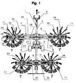
- the machine comprises a frame (1). It consists of a central beam (2) which has at its front end a coupling device (3) for attachment to a drive tractor and to its middle a crossbar (4) with two displacement wheels. (5 and 6) which rest on the ground.
- the frame (1) has four arms (7, 8, 9, 10) each carrying a rotor (11) for swathing products such as mowed grass or straw on the ground.
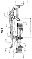
- Each rotor (11) has a housing (12) which is connected to the corresponding support arm (7, 8, 9, 10) in a manner to be described later.
- this housing (12) is housed a substantially vertical support shaft (13).
- This axis (13) extends downwards and carries at its lower end a carriage (14) equipped with carrying wheels (15) located under the rotor (11).
- the upper side of the housing (16) is provided with a ring gear which is located under the housing (12).
- This ring meshes with a drive pinion which is also under the housing (12).
- Said pinion is secured to a shaft which extends out of this housing (12) and which is connected to a hydraulic motor (17) which provide the drive in rotation.
- the said shaft could also be connected, with the help of drive shafts, to a PTO shaft of the tractor.
- the housing (16) is provided with bearings (18) through which arms (19) pass. These extend in the form of spokes and carry at their outer ends windrowing tools (20) constituted by forks. They are housed in said bearings (18) so as to turn on themselves.
- On the portion of the axis (13) in the housing (16) is mounted a fixed cam for controlling the tool arms (19) during windrowing work.
- each of these arms (19) has at its end which extends inside the housing (16) a lever with a roller which is guided in a known manner in a groove of the cam.
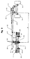
- the support arms (7, 8, 9, 10) are articulated on the central beam (2) by means of hinge pins (21) substantially horizontal and directed in the direction of advance (A).
- a hydraulic cylinder (22) which allows it to be moved around its hinge axis (21), to bring it from a substantially horizontal working position in a substantially vertical transport position and vice versa.
- These hydraulic cylinders (22) are articulated on the corresponding support arm (7, 8, 9 or 10) and on the beam (2). They can be connected to the hydraulic device of the tractor and be controlled from it.
- Two support arms (7 and 8) are located towards the front of the central beam (2) and the other two arms (9 and 10) towards the rear of the latter. They are all made in two telescopic parts (23 and 24).
- the first part (23) is connected to the axis of articulation (21) on the beam (2) and the second part (24) carries the corresponding rotor (11). It is connected to this second part (24) via an articulated connection device (25) allowing it to follow the uneven ground.
- Each second portion (24) is slidable relative to the first portion (23) to vary the position of the corresponding rotor (11) relative to the beam (2) between an inner position where its support axis (13) is located at a minimum distance (d) from the hinge axis (21) on the beam (2) and an outer position where its support axis (13) is at a maximum distance (D) from said hinge axis (21) .
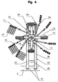
- the first telescopic portion (23) of each support arm (7, 8, 9 and 10) is made of two tubes (26 and 27) substantially parallel and interconnected by cross members (28).
- the second telescopic portion (24) of each support arm (7, 8, 9 and 10) is also made of two tubes (29 and 30) substantially parallel and interconnected by a cross member (31) located near their outer ends.
- Each support arm (7, 8, 9 and 10) comprises a hydraulic cylinder (32) which is connected to the crossbar (28) which is located near the inner end of the first telescopic part (23) and to the crossbar ( 31) which is located near the outer end of the second telescopic portion (24).
- This jack (32) is advantageously located between the tubes (26, 27, 29 and 30) which constitute the telescopic parts (23 and 24).
- These hydraulic cylinders (32) ensure the displacements of the second telescopic parts (24) to lengthen or shorten the support arms (7, 8, 9 and 10). For this, they can be connected, by means of pipes, to the hydraulic device of the tractor.
- the length of each guide section (33) is such as to guide the second telescopic portion (24) to a position where the value of the distance (D) is substantially twice the value of the distance (d). ).
- This additional guide section (33) extends the first telescopic portion (23) by about half the distance (d). It is in the form of tubes similar to the tubes (26 and 27) with, on their side directed downwards, openings (34) which extend over substantially their entire length (see Figure 4).
- This second portion (24) is substantially the same length as the first portion (23) with the guide section (33) included. Guiding between the two parts is thus optimal in all positions.
- the hydraulic cylinder (32) which moves the second portion (24) is relatively long, which allows it to have a significant stroke.
- the aforesaid arrangement makes it possible to lengthen the support arms (7 and 8) by a distance such that the working width can be doubled between the inner position and the outer position. It can also shorten them sufficiently so that they do not exceed, in the transport position, the authorized height.
- the machine is moved in the direction of advance A.
- the support arms (7 to 10) are lowered in substantially horizontal position and the wheels (15) of the rotors (11) move on the ground.
- These rotors (11) are arranged to form a V (see Figure 1). They are rotated so that they rotate in the direction of the arrows F and G.
- the tools (20) of the two most forward rotors (11) are controlled by their respective cams so that they pick up the forage on the front halves of their trajectories, move it towards the beam (2) and deposit it in the form of windrows.
- the tools (20) of the two rearmost rotors (11) are controlled similarly. They pick up all the fodder found on their trajectories, including that deposited by the two previous rotors, and collect it to form a central swath of large volume.
- the working width obtained with the rotors (11) can be modified using telescopic support arms (7 to 10) in particular depending on the processing capacity of the press or the forage harvester which is used to pick up the swath.
- the two arms (7 and 8) of the foremost rotors (11) can be extended so as to bring the corresponding rotors into the outer position where the working width is practically doubled compared to at the inner position.
- the second telescopic portions (24) of the support arms (7 and 8) are held by the additional guide sections (33).
- the working width can then be close to fifteen meters.
- said rotors (11) are below the additional guide sections (33), their fastening tabs (35) passing through the openings (34).
- the minimum working width is thus not limited by the length of said portion (23) and section (33) which serves to guide the second parts (24).
- the working width of the two rearmost rotors (11) may be smaller than that of the foremost rotors (11).
- the maximum elongation of their carrier arms (9 and 10) can thus be relatively short, so that that the second portions (24) are held correctly in the first portions (23) themselves. It is nevertheless possible to provide the same type of support arms at the rear as at the front.
- the support arms (7 to 10) are shortened to the maximum and are raised by means of the cylinders (22) in a substantially vertical position to reduce the size of the machine.
- This maximum shortening corresponds to the position in which the rotors (11) are brought closer to the beam (2) and are located at the distance (d) of the hinge pins (21) of their support arms (7 to 10). ). In this position, it is further possible to disassemble or fold up the tool arms (19) which are directed upwards to further reduce the height of the machine.
Landscapes
- Life Sciences & Earth Sciences (AREA)
- Environmental Sciences (AREA)
- Agricultural Machines (AREA)
- Harvesting Machines For Specific Crops (AREA)
- Control Of Multiple Motors (AREA)
- Glass Compositions (AREA)
- Paper (AREA)
- Processes Of Treating Macromolecular Substances (AREA)
- Separation By Low-Temperature Treatments (AREA)
- Compounds Of Unknown Constitution (AREA)
- Accommodation For Nursing Or Treatment Tables (AREA)
- Centrifugal Separators (AREA)
- Load-Engaging Elements For Cranes (AREA)
- Forklifts And Lifting Vehicles (AREA)
Claims (11)
- Heuwerbungsmaschine, insbesondere zum Schwaden von Futter, mit einem Rahmen (1), der mehrere Schwadrotoren (11) trägt, die in Drehung um im Wesentlichen vertikale Stützachsen (13) angetrieben werden können, wobei die Rotoren (11) mit Tragarmen (7, 8, 9 und 10) verbunden sind, die am Gestell (1) mit Hilfe von Gelenkachsen (21) angelenkt sind, um die sie von einer im Wesentlichen horizontalen Arbeitsposition in eine im Wesentlichen vertikale Transportposition und umgekehrt verschoben werden können, wobei die Tragarme (7 bis 10) jeweils in zwei Teleskopteilen (23 und 24) ausgeführt sind, von denen der erste (23) mit der Gelenkachse (21) an dem Rahmen (1) verbunden ist und der zweite (24) den entsprechenden Rotor (11) trägt, wobei dieser zweite Teil (24) in Bezug auf den ersten Teil (23) gleiten kann, um die Position des entsprechenden Rotors (11) in Bezug auf den Rahmen (1) zwischen einer inneren Position, in der sich seine Stützachse (13) in einem Mindestabstand (d) zur Gelenkachse (21) des entsprechenden Tragarms (7 bis 10) befindet, und einer äußeren Position, in der sich seine Stützachse (13) in einem Höchstabstand (D) zu der Gelenkachse befindet (21), zu verändern, dadurch gekennzeichnet, dass der erste Teleskopteil (23) von mindestens einem Tragarm (7 bis 10) einen zusätzlichen Führungsabschnitt (33) umfasst, der sich in seiner Verlängerung über die Stützachse (13) des entsprechenden Rotors (11) hinaus erstreckt, wenn sich dieser in der inneren Position befindet, und dessen Länge derart ist, dass sie es ermöglicht, den zweiten entsprechenden Teleskopteil (24) bis in eine äußere Position zu führen, in der der Wert des Abstandes (D) im Wesentlichen das Doppelte des Wertes des Abstandes (d) ist.
- Maschine nach Anspruch 1, dadurch gekennzeichnet, dass die ersten Teleskopteile (23) der Tragarme (7 und 8) der beiden am weitesten vorne befindlichen Rotoren (11) einen zusätzlichen Führungsabschnitt (33) umfassen.
- Maschine nach Anspruch 2, dadurch gekennzeichnet, dass der zusätzliche Führungsabschnitt (33) eine Länge gleich ungefähr der Hälfte des Abstandes (d) zwischen der Stützachse (13) des entsprechenden Rotors (11) in der inneren Position und der Gelenkachse (21) des entsprechenden Tragarms (7, 8) aufweist.
- Maschine nach Anspruch 3, dadurch gekennzeichnet, dass der zusätzliche Führungsabschnitt (33) Öffnungen (34) umfasst, die sich über seine ganze Länge erstrecken.
- Maschine nach Anspruch 2, dadurch gekennzeichnet, dass der zweite Teleskopteil (24) der Tragarme (7, 8) Befestigungseisen (35) für den entsprechenden Rotor (11) umfasst.
- Maschine nach den Ansprüchen 4 und 5, dadurch gekennzeichnet, dass sich die Befestigungseisen (35) der Rotoren (11) in den Öffnungen (34) der Führungsabschnitte (33) der ersten Teleskopteile (23) befinden, wenn sich die Tragarme (7 und 8) in der inneren Position befinden.
- Maschine nach irgend einem der vorhergehenden Ansprüche, dadurch gekennzeichnet, dass der erste Teleskopteil (23) jedes Tragarms (7 bis 10) in zwei im Wesentlichen parallelen Rohren (26 und 27) ausgeführt ist, die durch Querstreben (28) miteinander verbunden sind.
- Maschine nach irgend einem der vorhergehenden Ansprüche, dadurch gekennzeichnet, dass der zweite Teleskopteil (24) jedes Tragarms (7 bis 10) in zwei im Wesentlichen parallelen Rohren (29 und 30) ausgeführt ist, die durch eine Querstrebe (31) miteinander verbunden sind.
- Maschine nach irgend einem der vorhergehenden Ansprüche, dadurch gekennzeichnet, dass der erste Teleskopteil (23) inklusive des zusätzlichen Führungsabschnittes (33) und der zweite Teleskopteil (24) der Tragarme (7 und 8) im Wesentlichen dieselbe Länge haben.
- Maschine nach irgend einem der vorhergehenden Ansprüche, dadurch gekennzeichnet, dass jeder Tragarm (7 bis 10) einen Hydraulikzylinder (32) umfasst, der mit einer Querstrebe (28), die sich in der Nähe des inneren Endes des ersten Teleskopteils (23) befindet, und mit der Querstrebe (31) verbunden ist, die sich am äußeren Ende des zweiten Teleskopteils (24) befindet.
- Maschine nach Anspruch 10, dadurch gekennzeichnet, dass sich der Hydraulikzylinder (32) zwischen den Rohren (26, 27, 29 und 30) befindet, die die Teleskopteile (23 und 24) jedes Tragarms (7 bis 10) darstellen.
Applications Claiming Priority (2)
| Application Number | Priority Date | Filing Date | Title |
|---|---|---|---|
| FR0111659A FR2828988B1 (fr) | 2001-09-06 | 2001-09-06 | Machine de fenaison comportant des rotors lies a des bras porteurs realises en deux parties telescopiques |
| FR0111659 | 2001-09-06 |
Publications (2)
| Publication Number | Publication Date |
|---|---|
| EP1290936A1 EP1290936A1 (de) | 2003-03-12 |
| EP1290936B1 true EP1290936B1 (de) | 2006-04-12 |
Family
ID=8867108
Family Applications (1)
| Application Number | Title | Priority Date | Filing Date |
|---|---|---|---|
| EP02360258A Expired - Lifetime EP1290936B1 (de) | 2001-09-06 | 2002-09-04 | Heuwerbungsmaschine |
Country Status (6)
| Country | Link |
|---|---|
| US (1) | US6748730B2 (de) |
| EP (1) | EP1290936B1 (de) |
| AT (1) | ATE322813T1 (de) |
| DE (1) | DE60210550T2 (de) |
| DK (1) | DK1290936T3 (de) |
| FR (1) | FR2828988B1 (de) |
Families Citing this family (15)
| Publication number | Priority date | Publication date | Assignee | Title |
|---|---|---|---|---|
| US20070167681A1 (en) | 2001-10-19 | 2007-07-19 | Gill Thomas J | Portable imaging system employing a miniature endoscope |
| US10595710B2 (en) * | 2001-10-19 | 2020-03-24 | Visionscope Technologies Llc | Portable imaging system employing a miniature endoscope |
| FR2875377B1 (fr) | 2004-09-23 | 2007-01-19 | Kuhn Sa Sa | Andaineuse de vegetaux avec trois roues rateleuses |
| NL1037784C2 (nl) * | 2010-03-08 | 2011-09-09 | Forage Innovations Bv | Hooibouwinrichting. |
| NL1037815C2 (nl) * | 2010-03-18 | 2011-09-20 | Forage Innovations Bv | Hooibouwinrichting. |
| FR3007240B1 (fr) * | 2013-06-25 | 2015-06-12 | Kuhn Sa | Machine de recolte comportant un asservissement de la hauteur de relevage d'un outil de recolte |
| NL2014827B1 (en) * | 2015-05-19 | 2017-01-31 | Forage Innovations Bv | An agricultural machine and a method for proccesing crop. |
| DE102018116014A1 (de) * | 2018-07-02 | 2020-01-02 | Claas Saulgau Gmbh | Landwirtschaftliches Arbeitsgerät |
| GB201811406D0 (en) * | 2018-07-12 | 2018-08-29 | Agco Feucht Gmbh | Towed agricultural implement |
| GB201814800D0 (en) * | 2018-09-12 | 2018-10-24 | Agco Feucht Gmbh | Improved agricultural implement |
| GB201905205D0 (en) * | 2019-04-12 | 2019-05-29 | Agco Feucht Gmbh | Agricultural implement |
| GB201915531D0 (en) * | 2019-10-25 | 2019-12-11 | Agco Int Gmbh | Improved agricultural implement |
| AT523685B1 (de) * | 2020-04-08 | 2022-01-15 | Poettinger Landtechnik Gmbh | Verfahren zum Betreiben eines Mehrkreiselschwaders sowie Mehrkreiselschwader |
| CN113261430A (zh) * | 2021-05-21 | 2021-08-17 | 呼伦贝尔学院 | 一种竖直旋转式搂草机 |
| PL246843B1 (pl) * | 2022-10-01 | 2025-03-17 | Samasz Spolka Z Ograniczona Odpowiedzialnoscia | Maszyna do zbioru pasz objętościowych i słomy |
Family Cites Families (9)
| Publication number | Priority date | Publication date | Assignee | Title |
|---|---|---|---|---|
| DE1757499C3 (de) * | 1968-05-16 | 1974-09-26 | Maschinenfabrik Fahr Ag Gottmadingen, 7702 Gottmadingen | Kreiselzettwender |
| FR2548519B1 (fr) * | 1983-07-07 | 1986-04-04 | Kuhn Sa | Perfectionnement aux machines de fenaison en vue de leur transport |
| FR2582186B1 (fr) * | 1985-05-21 | 1989-05-05 | Kuhn Sa | Perfectionnement aux machines de fenaison munies de plusieurs roues rateleuses |
| DE8715405U1 (de) * | 1987-11-20 | 1989-03-23 | H. Niemeyer Söhne GmbH & Co KG, 4446 Hörstel | Heuwerbungsmaschine |
| FR2648983B1 (fr) * | 1989-06-28 | 1991-10-04 | Kuhn Sa | Machine agricole munie de deux bras telescopiques portant chacun un rotor |
| US5069022A (en) * | 1990-09-28 | 1991-12-03 | Befco, Inc. | Gang mower apparatus |
| FR2677213B1 (fr) * | 1991-06-05 | 1993-09-24 | Kuhn Sa | Machine agricole, notamment une andaineuse de vegetaux. |
| DE19916759B4 (de) * | 1999-04-14 | 2005-08-25 | Gebr. Pöttinger GmbH | Kreiselschwader |
| DE19952555C2 (de) * | 1999-11-01 | 2003-08-07 | Krone Bernhard Gmbh Maschf | Heuwerbungsmaschine |
-
2001
- 2001-09-06 FR FR0111659A patent/FR2828988B1/fr not_active Expired - Fee Related
-
2002
- 2002-09-04 DE DE60210550T patent/DE60210550T2/de not_active Expired - Lifetime
- 2002-09-04 DK DK02360258T patent/DK1290936T3/da active
- 2002-09-04 EP EP02360258A patent/EP1290936B1/de not_active Expired - Lifetime
- 2002-09-04 AT AT02360258T patent/ATE322813T1/de active
- 2002-09-05 US US10/234,154 patent/US6748730B2/en not_active Expired - Fee Related
Also Published As
| Publication number | Publication date |
|---|---|
| EP1290936A1 (de) | 2003-03-12 |
| ATE322813T1 (de) | 2006-04-15 |
| FR2828988A1 (fr) | 2003-03-07 |
| US6748730B2 (en) | 2004-06-15 |
| DK1290936T3 (da) | 2006-08-14 |
| FR2828988B1 (fr) | 2004-07-30 |
| DE60210550T2 (de) | 2006-11-30 |
| DE60210550D1 (de) | 2006-05-24 |
| US20030041584A1 (en) | 2003-03-06 |
Similar Documents
| Publication | Publication Date | Title |
|---|---|---|
| EP2839731B1 (de) | Futtererntemaschine | |
| EP1366650B1 (de) | Landwirschaftliche Maschine mit einer Vorrichtung für die Transportstellung | |
| EP1290936B1 (de) | Heuwerbungsmaschine | |
| EP1605748B1 (de) | Vorrichtung um produkte wie gras zu gruppieren | |
| EP2253186B1 (de) | Heuwerbungsmaschine | |
| EP1496734B1 (de) | Heuwerbungsmaschine | |
| EP0385899A1 (de) | Heuwerbungsmaschine mit mehreren Kreiseln | |
| FR2631208A1 (fr) | Perfectionnement aux machines agricoles avec un chassis porte-outils articule | |
| FR2663189A1 (fr) | Machine de fenaison pour l'andainage, comportant au moins deux roues rateleuses. | |
| EP0255458B1 (de) | Landmaschine zum seitlichen Versetzen und Wenden von Futterschwaden | |
| FR2613177A1 (fr) | Machine de fenaison | |
| EP0772969B1 (de) | Heuwerbungsmaschine mit mindestens einem Rotor zum Schwaden | |
| EP0692185B1 (de) | Heuwerbungsmaschine, namentlich ein Schwader mit gesteuerten Zinkentragarmen | |
| FR2746576A1 (fr) | Machine agricole du genre faneuse a rateaux rotatifs multiples, convertible d'une position de travail deployee a une position de transport ramassee | |
| EP0514302B1 (de) | Verbesserter Pflanzenschwader | |
| EP1142468B1 (de) | Heuwerbungsmaschine | |
| EP0954956B1 (de) | Heuwerbungsmaschine | |
| EP1696720B1 (de) | Heuerntemaschine mit einem gelenkigen rahmen | |
| EP0857413B1 (de) | Heuwerbungsmaschine | |
| FR2868905A1 (fr) | Pick up repliable a entrainement independant des deux elements de vis sans fin | |
| EP0914766B1 (de) | Heuwerbungsmachine | |
| EP0733302B1 (de) | Heuwerbungsmaschine | |
| FR2890526A1 (fr) | Machine de fenaison avec des structures laterales repliables | |
| FR3065147A1 (fr) | Dispositif aerateur d'andain et machine agricole equipee d'un tel dispositif | |
| FR2699044A1 (fr) | Machine de fenaison avec des roues de transport déplaçables en hauteur. |
Legal Events
| Date | Code | Title | Description |
|---|---|---|---|
| PUAI | Public reference made under article 153(3) epc to a published international application that has entered the european phase |
Free format text: ORIGINAL CODE: 0009012 |
|
| AK | Designated contracting states |
Kind code of ref document: A1 Designated state(s): AT BE BG CH CY CZ DE DK EE ES FI FR GB GR IE IT LI LU MC NL PT SE SK TR |
|
| AX | Request for extension of the european patent |
Extension state: AL LT LV MK RO SI |
|
| 17P | Request for examination filed |
Effective date: 20030912 |
|
| AKX | Designation fees paid |
Designated state(s): AT BE BG CH CY CZ DE DK EE ES FI FR GB GR IE IT LI LU MC NL PT SE SK TR |
|
| GRAP | Despatch of communication of intention to grant a patent |
Free format text: ORIGINAL CODE: EPIDOSNIGR1 |
|
| GRAS | Grant fee paid |
Free format text: ORIGINAL CODE: EPIDOSNIGR3 |
|
| GRAA | (expected) grant |
Free format text: ORIGINAL CODE: 0009210 |
|
| AK | Designated contracting states |
Kind code of ref document: B1 Designated state(s): AT BE BG CH CY CZ DE DK EE ES FI FR GB GR IE IT LI LU MC NL PT SE SK TR |
|
| PG25 | Lapsed in a contracting state [announced via postgrant information from national office to epo] |
Ref country code: IT Free format text: LAPSE BECAUSE OF FAILURE TO SUBMIT A TRANSLATION OF THE DESCRIPTION OR TO PAY THE FEE WITHIN THE PRESCRIBED TIME-LIMIT;WARNING: LAPSES OF ITALIAN PATENTS WITH EFFECTIVE DATE BEFORE 2007 MAY HAVE OCCURRED AT ANY TIME BEFORE 2007. THE CORRECT EFFECTIVE DATE MAY BE DIFFERENT FROM THE ONE RECORDED. Effective date: 20060412 Ref country code: SK Free format text: LAPSE BECAUSE OF FAILURE TO SUBMIT A TRANSLATION OF THE DESCRIPTION OR TO PAY THE FEE WITHIN THE PRESCRIBED TIME-LIMIT Effective date: 20060412 Ref country code: FI Free format text: LAPSE BECAUSE OF FAILURE TO SUBMIT A TRANSLATION OF THE DESCRIPTION OR TO PAY THE FEE WITHIN THE PRESCRIBED TIME-LIMIT Effective date: 20060412 Ref country code: IE Free format text: LAPSE BECAUSE OF FAILURE TO SUBMIT A TRANSLATION OF THE DESCRIPTION OR TO PAY THE FEE WITHIN THE PRESCRIBED TIME-LIMIT Effective date: 20060412 Ref country code: GB Free format text: LAPSE BECAUSE OF FAILURE TO SUBMIT A TRANSLATION OF THE DESCRIPTION OR TO PAY THE FEE WITHIN THE PRESCRIBED TIME-LIMIT Effective date: 20060412 Ref country code: CZ Free format text: LAPSE BECAUSE OF FAILURE TO SUBMIT A TRANSLATION OF THE DESCRIPTION OR TO PAY THE FEE WITHIN THE PRESCRIBED TIME-LIMIT Effective date: 20060412 |
|
| REG | Reference to a national code |
Ref country code: GB Ref legal event code: FG4D Free format text: NOT ENGLISH |
|
| REG | Reference to a national code |
Ref country code: CH Ref legal event code: EP |
|
| REF | Corresponds to: |
Ref document number: 60210550 Country of ref document: DE Date of ref document: 20060524 Kind code of ref document: P |
|
| REG | Reference to a national code |
Ref country code: IE Ref legal event code: FG4D Free format text: LANGUAGE OF EP DOCUMENT: FRENCH |
|
| PG25 | Lapsed in a contracting state [announced via postgrant information from national office to epo] |
Ref country code: SE Free format text: LAPSE BECAUSE OF FAILURE TO SUBMIT A TRANSLATION OF THE DESCRIPTION OR TO PAY THE FEE WITHIN THE PRESCRIBED TIME-LIMIT Effective date: 20060712 |
|
| PG25 | Lapsed in a contracting state [announced via postgrant information from national office to epo] |
Ref country code: ES Free format text: LAPSE BECAUSE OF FAILURE TO SUBMIT A TRANSLATION OF THE DESCRIPTION OR TO PAY THE FEE WITHIN THE PRESCRIBED TIME-LIMIT Effective date: 20060723 |
|
| REG | Reference to a national code |
Ref country code: DK Ref legal event code: T3 |
|
| PG25 | Lapsed in a contracting state [announced via postgrant information from national office to epo] |
Ref country code: PT Free format text: LAPSE BECAUSE OF FAILURE TO SUBMIT A TRANSLATION OF THE DESCRIPTION OR TO PAY THE FEE WITHIN THE PRESCRIBED TIME-LIMIT Effective date: 20060912 |
|
| PG25 | Lapsed in a contracting state [announced via postgrant information from national office to epo] |
Ref country code: BE Free format text: LAPSE BECAUSE OF NON-PAYMENT OF DUE FEES Effective date: 20060930 Ref country code: MC Free format text: LAPSE BECAUSE OF NON-PAYMENT OF DUE FEES Effective date: 20060930 Ref country code: LI Free format text: LAPSE BECAUSE OF NON-PAYMENT OF DUE FEES Effective date: 20060930 Ref country code: CH Free format text: LAPSE BECAUSE OF NON-PAYMENT OF DUE FEES Effective date: 20060930 |
|
| GBV | Gb: ep patent (uk) treated as always having been void in accordance with gb section 77(7)/1977 [no translation filed] |
Effective date: 20060412 |
|
| REG | Reference to a national code |
Ref country code: IE Ref legal event code: FD4D |
|
| PLBE | No opposition filed within time limit |
Free format text: ORIGINAL CODE: 0009261 |
|
| STAA | Information on the status of an ep patent application or granted ep patent |
Free format text: STATUS: NO OPPOSITION FILED WITHIN TIME LIMIT |
|
| 26N | No opposition filed |
Effective date: 20070115 |
|
| REG | Reference to a national code |
Ref country code: CH Ref legal event code: PL |
|
| BERE | Be: lapsed |
Owner name: KUHN S.A. Effective date: 20060930 |
|
| PG25 | Lapsed in a contracting state [announced via postgrant information from national office to epo] |
Ref country code: GR Free format text: LAPSE BECAUSE OF FAILURE TO SUBMIT A TRANSLATION OF THE DESCRIPTION OR TO PAY THE FEE WITHIN THE PRESCRIBED TIME-LIMIT Effective date: 20060713 |
|
| PG25 | Lapsed in a contracting state [announced via postgrant information from national office to epo] |
Ref country code: BG Free format text: LAPSE BECAUSE OF FAILURE TO SUBMIT A TRANSLATION OF THE DESCRIPTION OR TO PAY THE FEE WITHIN THE PRESCRIBED TIME-LIMIT Effective date: 20060712 Ref country code: EE Free format text: LAPSE BECAUSE OF FAILURE TO SUBMIT A TRANSLATION OF THE DESCRIPTION OR TO PAY THE FEE WITHIN THE PRESCRIBED TIME-LIMIT Effective date: 20060412 |
|
| PG25 | Lapsed in a contracting state [announced via postgrant information from national office to epo] |
Ref country code: LU Free format text: LAPSE BECAUSE OF NON-PAYMENT OF DUE FEES Effective date: 20060904 Ref country code: TR Free format text: LAPSE BECAUSE OF FAILURE TO SUBMIT A TRANSLATION OF THE DESCRIPTION OR TO PAY THE FEE WITHIN THE PRESCRIBED TIME-LIMIT Effective date: 20060412 |
|
| PG25 | Lapsed in a contracting state [announced via postgrant information from national office to epo] |
Ref country code: CY Free format text: LAPSE BECAUSE OF FAILURE TO SUBMIT A TRANSLATION OF THE DESCRIPTION OR TO PAY THE FEE WITHIN THE PRESCRIBED TIME-LIMIT Effective date: 20060412 |
|
| PGFP | Annual fee paid to national office [announced via postgrant information from national office to epo] |
Ref country code: DK Payment date: 20140822 Year of fee payment: 13 Ref country code: NL Payment date: 20140820 Year of fee payment: 13 |
|
| PGFP | Annual fee paid to national office [announced via postgrant information from national office to epo] |
Ref country code: AT Payment date: 20140825 Year of fee payment: 13 |
|
| REG | Reference to a national code |
Ref country code: DK Ref legal event code: EBP Effective date: 20150930 |
|
| REG | Reference to a national code |
Ref country code: AT Ref legal event code: MM01 Ref document number: 322813 Country of ref document: AT Kind code of ref document: T Effective date: 20150904 |
|
| REG | Reference to a national code |
Ref country code: NL Ref legal event code: MM Effective date: 20151001 |
|
| REG | Reference to a national code |
Ref country code: FR Ref legal event code: PLFP Year of fee payment: 15 |
|
| PG25 | Lapsed in a contracting state [announced via postgrant information from national office to epo] |
Ref country code: NL Free format text: LAPSE BECAUSE OF NON-PAYMENT OF DUE FEES Effective date: 20151001 Ref country code: AT Free format text: LAPSE BECAUSE OF NON-PAYMENT OF DUE FEES Effective date: 20150904 |
|
| PG25 | Lapsed in a contracting state [announced via postgrant information from national office to epo] |
Ref country code: DK Free format text: LAPSE BECAUSE OF NON-PAYMENT OF DUE FEES Effective date: 20150930 |
|
| REG | Reference to a national code |
Ref country code: FR Ref legal event code: PLFP Year of fee payment: 16 |
|
| REG | Reference to a national code |
Ref country code: FR Ref legal event code: PLFP Year of fee payment: 17 |
|
| PGFP | Annual fee paid to national office [announced via postgrant information from national office to epo] |
Ref country code: DE Payment date: 20180927 Year of fee payment: 17 Ref country code: FR Payment date: 20180925 Year of fee payment: 17 |
|
| REG | Reference to a national code |
Ref country code: DE Ref legal event code: R119 Ref document number: 60210550 Country of ref document: DE |
|
| PG25 | Lapsed in a contracting state [announced via postgrant information from national office to epo] |
Ref country code: DE Free format text: LAPSE BECAUSE OF NON-PAYMENT OF DUE FEES Effective date: 20200401 |
|
| PG25 | Lapsed in a contracting state [announced via postgrant information from national office to epo] |
Ref country code: FR Free format text: LAPSE BECAUSE OF NON-PAYMENT OF DUE FEES Effective date: 20190930 |