EP0857413B1 - Heuwerbungsmaschine - Google Patents
Heuwerbungsmaschine Download PDFInfo
- Publication number
- EP0857413B1 EP0857413B1 EP98440014A EP98440014A EP0857413B1 EP 0857413 B1 EP0857413 B1 EP 0857413B1 EP 98440014 A EP98440014 A EP 98440014A EP 98440014 A EP98440014 A EP 98440014A EP 0857413 B1 EP0857413 B1 EP 0857413B1
- Authority
- EP
- European Patent Office
- Prior art keywords
- axis
- ground
- rotor
- balance beam
- machine according
- Prior art date
- Legal status (The legal status is an assumption and is not a legal conclusion. Google has not performed a legal analysis and makes no representation as to the accuracy of the status listed.)
- Expired - Lifetime
Links
- 230000008878 coupling Effects 0.000 claims description 2
- 238000010168 coupling process Methods 0.000 claims description 2
- 238000005859 coupling reaction Methods 0.000 claims description 2
- 230000000284 resting effect Effects 0.000 claims 3
- 239000000969 carrier Substances 0.000 abstract description 5
- 239000002689 soil Substances 0.000 abstract 1
- 238000006073 displacement reaction Methods 0.000 description 5
- 230000005540 biological transmission Effects 0.000 description 3
- 238000013459 approach Methods 0.000 description 1
- 230000015572 biosynthetic process Effects 0.000 description 1
- 210000005069 ears Anatomy 0.000 description 1
- 239000004459 forage Substances 0.000 description 1
- 238000005096 rolling process Methods 0.000 description 1
- 238000006467 substitution reaction Methods 0.000 description 1
- 230000017105 transposition Effects 0.000 description 1
Images


Classifications
-
- A—HUMAN NECESSITIES
- A01—AGRICULTURE; FORESTRY; ANIMAL HUSBANDRY; HUNTING; TRAPPING; FISHING
- A01D—HARVESTING; MOWING
- A01D78/00—Haymakers with tines moving with respect to the machine
- A01D78/08—Haymakers with tines moving with respect to the machine with tine-carrying rotary heads or wheels
- A01D78/10—Haymakers with tines moving with respect to the machine with tine-carrying rotary heads or wheels the tines rotating about a substantially vertical axis
- A01D78/105—Ground support for rotors
-
- A—HUMAN NECESSITIES
- A01—AGRICULTURE; FORESTRY; ANIMAL HUSBANDRY; HUNTING; TRAPPING; FISHING
- A01B—SOIL WORKING IN AGRICULTURE OR FORESTRY; PARTS, DETAILS, OR ACCESSORIES OF AGRICULTURAL MACHINES OR IMPLEMENTS, IN GENERAL
- A01B73/00—Means or arrangements to facilitate transportation of agricultural machines or implements, e.g. folding frames to reduce overall width
-
- B—PERFORMING OPERATIONS; TRANSPORTING
- B60—VEHICLES IN GENERAL
- B60G—VEHICLE SUSPENSION ARRANGEMENTS
- B60G2300/00—Indexing codes relating to the type of vehicle
- B60G2300/08—Agricultural vehicles
-
- B—PERFORMING OPERATIONS; TRANSPORTING
- B60—VEHICLES IN GENERAL
- B60G—VEHICLE SUSPENSION ARRANGEMENTS
- B60G2300/00—Indexing codes relating to the type of vehicle
- B60G2300/40—Variable track or wheelbase vehicles
Definitions
- the present invention relates to a haymaking machine which comprises a frame carrying at least one rotor for moving plants on the ground, which rotor has a hub which is provided with tool-carrying arms and which is mounted on an axis central substantially vertical or inclined in the direction of travel so to be able to rotate on the latter, said axis being linked to the frame and comprising at its lower end a support device on the ground including at least one pendulum which is mounted on a substantially horizontal pivot axis and which is provided with two load-bearing wheels rolling on the ground during work.
- the pendulum with the two carrying wheels allows reduce the amount of movement transmitted to the rotor when the load wheels pass on unevennesses. Consequently, said rotor adapts better to the ground surface and can advance at higher speed.
- the central axis and the rotor are raised relative to the load wheels to keep the tools away from ground work.
- the uplift thus obtained remains relatively small, however.
- the working tools can catch obstacles which are on the ground.
- the rotor must pass over an already formed swath, its tools can catch and disperse forage.
- cornering load-bearing wheels rip on the ground. This leads to rapid wear of the latter and of their supports.
- the object of the present invention is to propose a machine which does not have the aforementioned drawbacks.
- an important characteristic of the invention consists in that the ground support device includes means for moving the or each pendulum around its pivot axis in an oblique position in which one of its two carrying wheels and the rotor with its tools are removed from the ground for the purpose of transport. Said displacement of the rocker (s) can be relatively large. The rotor is then lifted so that its working tools are sufficiently far from the ground. In addition, the rotor only rests on one of the two carrying wheels of the rocker (s). The shifting of the wheels on the ground in the turns is thus removed.
- the means for moving the or each pendulum comprises in particular a hydraulic cylinder. This can be controlled from the tractor used to animate the machine. The transposition of the machine from the working position into the transport position and vice versa is thus relatively easy.
- the support device for ground comprises a crosspiece which has at least one axis on which is articulated a pendulum, which cross member is articulated relative to the central axis of the rotor at means of a substantially horizontal axis, the means of displacement of the pendulum being constituted by a hydraulic cylinder which is articulated on flanges connected to the central axis and on a crossbar lever and by a retaining rod for the or each pendulum.
- This arrangement allows in particular to obtain a greater uplift rotor for transport.
- the machine according to the first example embodiment includes a frame (1) to which is connected a rotor (2) for moving plants lying on the ground.
- This frame (1) is essentially constituted by a hollow beam (3).
- a drawbar (4) is articulated, by means of an axis (5) substantially horizontal, on the front end of the beam (3).
- This drawbar (4) allows the attachment to a tractor (not shown) used to move the machine in direction (A).
- a hydraulic adjustment cylinder (6) is articulated both on the beam (3) and on a hanger (7) integral with the drawbar (4).
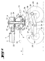
- the rotor (2) has a hub (8) in the form of a housing. This one is mounted on a central axis (9) by means of bearings (10, 11), so that it can rotate around.
- This central axis (9) is substantially vertical or slightly inclined in the advancement direction (A). It is housed in a bearing (12) of a housing (13) which part of the frame (1) and is immobilized in rotation in this bearing (13) by a key (14).
- the hub or casing (8) carries several arms (15) which extend in one plane practically horizontal. Only one of these arms (15) is shown in FIG. 1, in order to preserve the clarity of the drawing. They are provided, at their most remote from said hub or casing (8), working tools (16) in the form of forks raking.
- Each of these arms (15) is mounted in a bearing of the hub or casing (8) so as to be able to pivot on itself, that is to say around its axis longitudinal geometric.
- a cam control (17) which is fixed on the central axis (9).
- Each tool arm (15) has at its end located inside the hub or casing (8), a lever (18) with a roller (19) which is guided in said cam (17).
- the rotor (2) can be rotated on the central axis (9) from the tractor PTO shaft.
- the beam (3) carries at its end before a housing (20) with an input shaft (21) to which a shaft can be connected gimbals the other end of which is engaged with said PTO shaft.
- a transmission shaft (22) which extends from the casing (20) up to the rotor (2). It has a pinion (23) which meshes with a crown toothed (24) which is secured to the housing-shaped hub (8).
- the central axis (9) carries at its lower end a base (25) on which is screwed a device (26) for supporting the ground.
- This consists of a substantially horizontal plate (27) on which two legs are welded (28 and 29) which are directed downwards and rearwards and which carry a cross-member (30) with two pendulums (31, 32) each of which is provided with two carrying wheels (33 and 34).
- the crosspiece (30) is U-shaped. Its two ends are directed towards forward. On each of them is fixed a pivot axis (35, 36) substantially horizontal.
- the pendulums (31, 32) are mounted on these pivot axes (35, 36) so that you can turn on them at least a certain angle.
- One of the wheels carriers (33, 34) of each balance (31, 32) is located at the front of the axis of pivot (35, 36) corresponding and the other at the rear thereof. Moreover, the two supporting wheels (33, 34) of each balance (31, 32) are offset one by compared to each other.
- the foremost wheels (33) are located on the inner side of the corresponding balance (31, 32) while the wheels (34) which are behind are located on the outside of the corresponding pendulum (31, 32). This provision allows the wheels (33 and 34) to be brought as close as possible to the working tools (16), in order to make them follow the unevenness of the ground.
- the device (26) for supporting the ground also comprises means (37) for move each balance (31, 32) around its pivot axis (35, 36) and the maintain in a position in which one of its two carrying wheels (33, 34) is far from the ground.
- This means (37) comprises a hydraulic cylinder (38).
- the body thereof is articulated with a substantially horizontal axis (39) on two flanges (40, 41) which are integral with the plate (27) which is itself fixed to the central axis (9).
- the rod of the hydraulic cylinder (38) is articulated with an axis substantially horizontal (42) on an intermediate piece (43).
- This intermediate piece (43) is substantially V-shaped with two arms pointing down and forward.
- Each of these is articulated on a substantially horizontal axis (44) of a yoke (45, 46) secured to the front end of one of the pendulums (31, 32).
- Each branch has an oblong hole (47) in which the axis is housed corresponding articulation (44).
- the length of each oblong hole (47) is such that the pendulums (31 and 32) can pivot freely with the wheels carriers (33 and 34) when these follow the unevenness of the ground.
- the ground support device (48) also includes a U-shaped crosspiece (30) which has two axes (35 and 36) substantially horizontal, on which the pendulums (31 and 32) are articulated with the wheels carriers (33 and 34).
- This crosspiece (30) has ears (49) with an axis articulation (50) substantially horizontal and transverse to the direction progress (A). This is guided in two arms (51, 52) which are welded on the plate (27) which is itself screwed onto the base (25) of the central axis (9).
- the crosspiece (30) additionally comprises a lever (53) which is directed towards the front and towards the high.
- a displacement means (54) includes a hydraulic cylinder (55) which is articulated both on said lever (53) by means of an axis (56) and by means of an axis (57) on two flanges (58) integral with the plate (27) and one of which is located on the right and the other to the left of said hydraulic cylinder (55).
- the axes of articulation (50, 56 and 57) are substantially parallel to each other.
- Means of transport (54) additionally comprises a transverse bar (59) which is fixed to the plate (27) and which is provided at each end with a hinge pin (60, 61) directed laterally.
- each of these axes (60, 61) is mounted one end of a retaining rod (62, 63).
- the other end of each rod (62, 63) is articulated on an axis (64) of a yoke (65, 66) provided on each balance (31, 32).
- Each yoke (65, 66) is located near the front end of the corresponding pendulum (31, 32).
- Each rod of retainer (62, 63) has an oblong orifice (67) through which the axis (64) passes corresponding.
- the length of the oblong holes (67) is such that the pendulums (31, 32) can pivot freely around the axes (35, 36) following the uneven ground.
- the articulation axes (60, 61, 64) of the retaining rods (62, 63) are substantially horizontal and transverse to the direction of advance (A).
- the machine according to the embodiment of Figures 7 and 8 comprises a frame (1) with two rotors (2, 2 '). These are similar to the rotor (2) in the example according to Figures 4 to 6 and are no longer described in detail.
- the frame (1) consists essentially two hollow beams (68 and 69).
- the first beam (68) is linked to the central axis (9) of the first rotor (2) by means of an elbow (70). It brings to its foremost end a drawbar (71) and a hydraulic cylinder (72) for the adjusting the position of said drawbar (71).
- the second beam (69) is made in two parts (73 and 74) hinged together by means of an axis (75) substantially horizontal.
- the front part (73) is linked to the central axis (9) of the rotor (2) so that that she can turn around.
- the rear part (74) is linked to the rotor (2 '), the axis central (9 ') of the latter which can rotate relative to the rear part (74) and can be immobilized in various positions. This brings the rotor rear (2 ') in different positions relative to the front rotor (2). training in rotation of these rotors (2 and 2 ') is ensured by means of transmission shafts located in the beams (68 and 69).
- the machine according to the example shown in Figure 9 has a frame (1) composed essentially by a longitudinal beam (76) provided with a device coupling to a tractor and by a transverse beam (77). This can be made in one or more parts and carries several rotors (78) arranged one to next to each other.
- Each of these rotors (78) has a plate-shaped hub (79) which is mounted on a central axis (80) so that it can rotate around.
- This axis is housed in a bearing (81) of a housing (82) which is integral with the transverse beam (77). It is slightly inclined in the direction of travel (A).
- a crank (83) which allows said transverse beam (77) to be displaced about an axis of articulation (84) in order to modify the inclination of the axes (80) of all the rotors (78).
- the hub (79) of each rotor (78) has several arms (85) which extend more or less radially and which have at their ends outside of the working tools (86) in the form of forks.
- each central axis (80) is provided with a device (87) ground support.
- This consists of a balance (88) articulated on an axis transverse (89) which is integral with the central axis (80).
- the pendulum (88) has two carrying wheels (90 and 91), one of which is located at the front and the other at the rear of the transverse axis (89).
- Said device (87) for supporting the ground comprises means (92) to move the pendulum (88) and hold it in a position in which the load-bearing wheel (90) is moved away from the ground for transport.
- This means (92) is constituted by a hydraulic cylinder (93) which is articulated by means of an axis (98) on a fitting (94) integral with the central axis (80) and on the balance (88). This last comprises near its front end a yoke (95) with an oblong orifice (96).
- a hinge pin (97) which is integral with the hydraulic cylinder (93) is housed in said oblong orifice (96), which allows the pendulum (88) to pivot around its hinge pin (89) when the supporting wheels (90 and 91) pass over inclines.
- Transmission shafts (99) are housed in the beam transverse (77) for the rotational drive of the rotors (78).
- the swather according to Figures 1 to 3 is moved in the direction (A) using a tractor.
- the rotor (2) is then rotated in the direction (F) around the central axis (9) from the PTO shaft of said tractor.
- the cam (17) controls the tool-carrying arms (15), by through the levers (18) and the rollers (19), so that they move their working tools (16). So, on the front part of their trajectory, these tools (16) are substantially vertical and collect the products lying on the ground. Then, on the lateral part of their trajectory, the tools (16) are raised so they deposit the products collected in the form of a swath. Finally, on the part back of their trajectory, they gradually return to the position for to pick up.
- the hydraulic cylinder (38) is elongated and the hinge pin (44) of the yoke (45, 46) of each balance (31, 32) is located substantially in the middle of the oblong holes (47) of the intermediate piece (43).
- the load wheels (33 and 34) pass on bumps or in recesses, they pivot with the balance (31, 32) corresponding around the axis of articulation (35, 36) of the latter with the crosspiece (30).
- the height displacements of the wheels (33 and 34) are then greater that the movements of the pendulum (31, 32) corresponding to the level of its axis articulation (35, 36). Therefore, displacements of the crosspiece (30) and by Therefore the entire rotor (2) remains relatively small. This is so much more stable and it can move faster.
- the rotational drive of the rotor (2) is cut.
- the cylinders hydraulics (6 and 38) are operated from the tractor.
- the hydraulic cylinder (38) retracts and pulls the intermediate piece (43) backwards.
- This turns the pendulums (31, 32) around the pivot axes (35, 36) in a position oblique to the ground (see Figure 3).
- the carrying wheels front (33) are remote from the ground.
- the rotor (2) is raised and its working tools (16) are far from the ground. It then only rests on the ground through two rear wheels (34).
- the hydraulic cylinder (6) lengthens and rotates the front of the frame (1) relative to the drawbar (4) so that the rotor (2) is substantially horizontal.
- the working tools (16) do not catch the obstacles that may be on the ground and the load wheels (34) do not respond on the ground in turns.
- the rake according to the example in Figures 4 to 6 works in the same way than that shown in Figures 1 to 3.
- the hydraulic cylinder (55) is retracted into the working position.
- the pendulums (31 and 32) are in a horizontal position, the axes of articulations (64) of their yokes (65 and 66) are located in the middle of the oblong holes (67) of the retaining rods (62 and 63).
- Said pendulums (31 and 32) can thus pivot around their axes (35 and 36) on the crosspiece (30), when the carrying wheels (33 and 34) meet unevennesses.
- the hydraulic cylinder (55) of the device (48) for supporting the ground is controlled so that it lengthens.
- the lever (53) pushes the crossbar (30) down, which raises the whole rotor (2) by pivoting about the articulation axis (50).
- the crossbar (59) pulls then the retaining rods (62 and 63) upwards.
- These drive the pendulums (31 and 32) and rotate them around their pivot axes (35 and 36), in an oblique position relative to the ground.
- the front wheels (33) are then distant from the ground and only the rear wheels (34) rest thereon.
- the hydraulic cylinder (6) is actuated so that it lengthens and makes pivot the front of the frame (1) relative to the drawbar (4) so that the rotor (2) is substantially horizontal.
- the working mode of the rotors (2 and 2 ') of the swather according to Figures 7 and 8 is the same as that described in connection with the rotor (2) of the rake shown in Figures 1 to 3.
- the second rotor (2 ') can be moved laterally, around the central axis (9) of the first rotor (2). It can thus be transposed in a position such that each rotor (2 and 2 ') forms its own swath or in a position where the second rotor (2 ') takes up the swath deposited by the first rotor (2) and ensures the formation of a swath of greater volume.
- the machine is then carried by the only rear wheels (34 and 34 ') of the two rotors (2 and 2 '). In this position, the distance between the working tools (16 and 16 ') and the ground is very important and the wheels (34 and 34 ') do not rip on the ground in the turns.
- the tedder according to figure 9 is also moved in direction (A) at using a tractor during work.
- the rotors (78) are rotated from the tractor, around their respective central axes (80), so that they turn two by two in convergence at the front.
- their tools work (86) pick up the plants on the ground, move them to the rear between the converging rotors (78) and spread them again behind the machine while causing them to overturn.
- the load wheels (90 and 91) roll on the ground.
- the hinge pin (97) of the cylinder hydraulic (93) with the yoke (95) of the balance (88) of each rotor (78) is located in the middle of the oblong hole (96) of said yoke (95).
- the load wheels (90 and 91) and the pendulum (88) can thus move up and down around pivot axis (89) to follow the unevenness of the ground.
- crank (83) and the jacks hydraulics (93) are operated in opposite directions.
Landscapes
- Life Sciences & Earth Sciences (AREA)
- Environmental Sciences (AREA)
- Engineering & Computer Science (AREA)
- Mechanical Engineering (AREA)
- Soil Sciences (AREA)
- Agricultural Machines (AREA)
- Soil Working Implements (AREA)
- Glass Compositions (AREA)
- Paper (AREA)
- Control Of Multiple Motors (AREA)
- Organic Low-Molecular-Weight Compounds And Preparation Thereof (AREA)
- Developing Agents For Electrophotography (AREA)
- Lubricants (AREA)
- Forklifts And Lifting Vehicles (AREA)
- Handcart (AREA)
Claims (10)
- Heuwerbungsmaschine mit einem Rahmen (1), der mit mindestens einem Rotor (2, 2', 78) verbunden ist, um Pflanzengut über den Boden zu bewegen, wobei der Rotor (2, 2', 78) eine Nabe (8, 8', 79) besitzt, die mit Werkzeugtragarmen (15, 15', 85) versehen und an einer im Wesentlichen vertikalen oder in Fahrtrichtung (A) geneigten zentralen Achse (9, 9', 80) angebracht ist, so dass sie sich um diese drehen kann, wobei die Achse (9, 9', 80) mit dem Rahmen (1) verbunden ist und an ihrem unteren Ende eine Vorrichtung (26, 48, 48', 87) zur Abstützung auf dem Boden mit mindestens einer Schwinge (31, 31', 32, 32', 88) aufweist, die an einer im Wesentlichen horizontalen Schwenkachse (35, 35', 36, 36', 89) angebracht und mit zwei während des Betriebs über den Boden rollenden Tragrädern (33, 33', 34, 34', 90, 91) versehen ist, dadurch gekennzeichnet, dass die Vorrichtung (26, 48, 48', 87) zur Abstützung auf dem Boden ein Mittel (37, 54, 54', 92) zur Bewegung der oder jeder Schwinge (31, 31', 32, 32', 88) um ihre Schwenkachse (35, 36, 35', 36', 89) in eine schräge Stellung umfasst, in der eines ihrer beiden Tragräder (33, 33', 34, 34', 90, 91) und der Rotor (2, 2', 78) mit seinen Arbeitswerkzeugen (16) zum Transport vom Boden entfernt sind.
- Maschine nach Anspruch 1, dadurch gekennzeichnet, dass das Mittel (37, 54, 54', 92) zur Bewegung jeder Schwinge (31, 31', 32, 32', 88) mindestens einen Hydraulikzylinder (38, 55, 55', 93) umfasst.
- Maschine nach Anspruch 2, dadurch gekennzeichnet, dass der Hydraulikzylinder (93) an einem fest mit der zentralen Achse (80) verbundenen Verbinder (94) und an der entsprechenden Schwinge (88) angelenkt ist.
- Maschine nach Anspruch 3, dadurch gekennzeichnet, dass die Schwinge (88) einen Bügel (95) mit einem Langloch (96) enthält, in dem eine Gelenkachse (97) des Hydraulikzylinders (93) untergebracht ist.
- Maschine nach Anspruch 2, dadurch gekennzeichnet, dass der Hydraulikzylinder (38) an mit der zentralen Achse (9) verbundenen Flanschen (40, 41) und an einem Zwischenstück (43) angelenkt ist, das seinerseits an jeder Schwinge (31, 32) angelenkt ist.
- Maschine nach Anspruch 5, dadurch gekennzeichnet, dass jede Schwinge (31, 32) einen Bügel (45, 46) mit einer Gelenkachse (44) umfasst und dass das Zwischenstück (43) an jedem Ende ein Langloch (47) enthält, in dem sich die Achse (44) befindet.
- Maschine nach Anspruch 1, dadurch gekennzeichnet, dass die Vorrichtung (48, 48') zur Abstützung auf dem Boden einen Querträger (30, 30') umfasst, der mindestens eine Achse (35, 35', 36, 36') aufweist, an die eine Schwinge (31, 31', 32, 32') angelenkt ist, wobei der Querträger (30, 30') mittels einer im Wesentlichen horizontalen Achse (50, 50') bezüglich der zentralen Achse (9, 9') des entsprechenden Rotors (2, 2') angelenkt ist und, dass das Mittel (54, 54') durch einen Hydraulikzylinder (55, 55'), der an mit der zentralen Achse (9, 9') verbundenen Flanschen (58) und an einem Hebel (53, 53') des Querträgers (30, 30') angelenkt ist, und durch eine Haltestange (62, 62', 63, 63') für jede Schwinge (31,31', 32,32') gebildet wird.
- Maschine nach Anspruch 7, dadurch gekennzeichnet, dass jede Haltestange (62, 62', 63, 63') an einer mit der zentralen Achse (9, 9') verbundenen Querstange (59, 59') und in einem Bügel (65, 65', 66, 66') der entsprechenden Schwinge (31, 31', 32, 32') angelenkt ist.
- Maschine nach Anspruch 8, dadurch gekennzeichnet, dass sich der Bügel (65, 65', 66, 66') in der Nähe des vorderen Endes der entsprechenden Schwinge (31,31', 32,32') befindet.
- Maschine nach Anspruch 8, dadurch gekennzeichnet, dass jede Haltestange (62, 62', 63, 63') ein Langloch (67, 67') aufweist und der entsprechende Bügel (65, 65', 66, 66') eine sich im Langloch (67, 67') erstreckende Achse (64, 64') besitzt.
Applications Claiming Priority (2)
| Application Number | Priority Date | Filing Date | Title |
|---|---|---|---|
| FR9701710 | 1997-02-11 | ||
| FR9701710A FR2759245B1 (fr) | 1997-02-11 | 1997-02-11 | Machine de fenaison avec un dispositif d'appui au sol incluant au moins un balancier avec deux roues porteuses et un moyen pour deplacer ce balancier en vue du transport |
Publications (2)
| Publication Number | Publication Date |
|---|---|
| EP0857413A1 EP0857413A1 (de) | 1998-08-12 |
| EP0857413B1 true EP0857413B1 (de) | 2003-04-16 |
Family
ID=9503695
Family Applications (1)
| Application Number | Title | Priority Date | Filing Date |
|---|---|---|---|
| EP98440014A Expired - Lifetime EP0857413B1 (de) | 1997-02-11 | 1998-02-04 | Heuwerbungsmaschine |
Country Status (5)
| Country | Link |
|---|---|
| EP (1) | EP0857413B1 (de) |
| AT (1) | ATE237217T1 (de) |
| DE (1) | DE69813336T2 (de) |
| DK (1) | DK0857413T3 (de) |
| FR (1) | FR2759245B1 (de) |
Cited By (1)
| Publication number | Priority date | Publication date | Assignee | Title |
|---|---|---|---|---|
| NL1029351C2 (nl) | 2005-06-28 | 2007-01-02 | Lely Entpr Ag | Hooibouwmachine en machine. |
Families Citing this family (6)
| Publication number | Priority date | Publication date | Assignee | Title |
|---|---|---|---|---|
| FR2798817B1 (fr) * | 1999-09-23 | 2002-05-31 | Kuhn Sa | Machine de fenaison, notamment une andaineuse avec plusieurs rotors s'appuyant sur le sol au moyen de roues porteuses |
| DE19952555C2 (de) * | 1999-11-01 | 2003-08-07 | Krone Bernhard Gmbh Maschf | Heuwerbungsmaschine |
| DE10006737A1 (de) * | 2000-02-15 | 2001-08-16 | Claas Saulgau Gmbh | Landwirtschaftliche Arbeitsmaschine |
| FR2881023B1 (fr) * | 2005-01-26 | 2008-07-04 | Gyrland Ind Sas Soc Par Action | Rotor d'andaineur |
| DE202018106264U1 (de) * | 2018-11-02 | 2018-11-19 | Pöttinger Landtechnik Gmbh | Landwirtschaftliches Anbaugerät |
| DE102023130714A1 (de) * | 2023-11-07 | 2025-05-08 | Krone Agriculture Se | Landwirtschaftliches Fahrzeuggespann |
Family Cites Families (9)
| Publication number | Priority date | Publication date | Assignee | Title |
|---|---|---|---|---|
| DE2002746C3 (de) * | 1970-01-22 | 1978-08-03 | Fella-Werke Gmbh, 8501 Feucht | Heuwerbungmaschine |
| DE2004349A1 (de) * | 1970-01-30 | 1971-08-05 | Fella Werke GmbH, 8501 Feucht | Heuwerbungsmaschine |
| DE8811010U1 (de) * | 1988-03-17 | 1988-10-27 | Claas Saulgau GmbH, 7968 Saulgau | Kreiselheuer |
| DE3926382A1 (de) * | 1989-08-10 | 1991-02-14 | Fella Werke Gmbh | Landwirtschaftliche maschine |
| DE4015767A1 (de) * | 1990-05-16 | 1991-11-21 | Poettinger Alois Landmasch | Heuwerbungsmaschine |
| DE4122072C2 (de) * | 1991-07-04 | 2003-07-31 | Claas Saulgau Gmbh | Fahrwerk für Kreiselheumaschinen, wie Kreiselschwader |
| FR2702336B1 (fr) * | 1993-03-12 | 1995-05-05 | Kuhn Sa | Machine de fenaison perfectionnée. |
| FR2705861B1 (fr) * | 1993-06-04 | 1995-08-18 | Kuhn Sa | Machine de fenaison avec un dispositif de transport déplaçable. |
| DE9320479U1 (de) * | 1993-06-25 | 1994-08-25 | Claas Saulgau Gmbh, 88348 Saulgau | Frei schwenkbare Nachlaufräder für landwirtschaftliche Arbeitsmaschinen, insbesondere Kreiselheumaschinen |
-
1997
- 1997-02-11 FR FR9701710A patent/FR2759245B1/fr not_active Expired - Fee Related
-
1998
- 1998-02-04 DK DK98440014T patent/DK0857413T3/da active
- 1998-02-04 EP EP98440014A patent/EP0857413B1/de not_active Expired - Lifetime
- 1998-02-04 DE DE69813336T patent/DE69813336T2/de not_active Expired - Lifetime
- 1998-02-04 AT AT98440014T patent/ATE237217T1/de active
Cited By (3)
| Publication number | Priority date | Publication date | Assignee | Title |
|---|---|---|---|---|
| NL1029351C2 (nl) | 2005-06-28 | 2007-01-02 | Lely Entpr Ag | Hooibouwmachine en machine. |
| EP1738635A1 (de) | 2005-06-28 | 2007-01-03 | Lely Enterprises AG | Heuwerbungsmaschine und Maschine |
| US7398983B2 (en) | 2005-06-28 | 2008-07-15 | Lely Enterprises Ag | Haymaking machine and a machine |
Also Published As
| Publication number | Publication date |
|---|---|
| DE69813336D1 (de) | 2003-05-22 |
| FR2759245A1 (fr) | 1998-08-14 |
| ATE237217T1 (de) | 2003-05-15 |
| FR2759245B1 (fr) | 1999-04-23 |
| EP0857413A1 (de) | 1998-08-12 |
| DE69813336T2 (de) | 2004-02-05 |
| DK0857413T3 (da) | 2003-07-21 |
Similar Documents
| Publication | Publication Date | Title |
|---|---|---|
| EP1366650B1 (de) | Landwirschaftliche Maschine mit einer Vorrichtung für die Transportstellung | |
| FR2691041A1 (fr) | Machine de coupe, notamment faucheuse, s'adaptant aisément au relief du sol. | |
| CA2833103A1 (fr) | Machine agricole avec un dispositif de repliage perfectionne | |
| EP0318407A1 (de) | Heuerntemaschine mit mindestens einem Rechrad mit gesteuerten Werkzeug-Tragarmen | |
| FR2631208A1 (fr) | Perfectionnement aux machines agricoles avec un chassis porte-outils articule | |
| EP1290936B1 (de) | Heuwerbungsmaschine | |
| EP1076482B1 (de) | Heuerntemaschine mit mindestens einem rotor zum schwaden mit in position verstellbarem leitblech | |
| EP0857413B1 (de) | Heuwerbungsmaschine | |
| EP0772969B1 (de) | Heuwerbungsmaschine mit mindestens einem Rotor zum Schwaden | |
| FR2736503A1 (fr) | Machine agricole, notamment faneuse a rateaux rotatifs multiples | |
| EP0692185B1 (de) | Heuwerbungsmaschine, namentlich ein Schwader mit gesteuerten Zinkentragarmen | |
| EP0514302B1 (de) | Verbesserter Pflanzenschwader | |
| EP0797913B1 (de) | Heuwerbungsmaschine | |
| EP0554200B1 (de) | Heuwerbungsmaschine mit einem mit gesteuerten Stützrädern versehenen Rahmen | |
| FR2534110A1 (fr) | Dispositif destine a supporter, au moins partiellement, le poids d'une machine agricole | |
| FR2707450A1 (fr) | Machine de fenaison avec des rotors de fanage ou d'andainage munis de roues d'appui au sol. | |
| EP0733302B1 (de) | Heuwerbungsmaschine | |
| EP1926363A2 (de) | Heuerntemaschine mit faltbaren seitlichen strukturen | |
| EP0914766B1 (de) | Heuwerbungsmachine | |
| EP1013161B1 (de) | Heuwerbungsmaschine | |
| FR2798817A1 (fr) | Machine de fenaison, notamment une andaineuse avec plusieurs rotors s'appuyant sur le sol au moyen de roues porteuses | |
| EP4272538A1 (de) | Gesicherte heuwerbungsmaschine und methode dazu | |
| FR3114479A1 (fr) | Machine agricole trainée de récolte avec un essieu réglable | |
| FR2699044A1 (fr) | Machine de fenaison avec des roues de transport déplaçables en hauteur. | |
| FR2683697A1 (fr) | Dispositif de transport de machines agricoles. |
Legal Events
| Date | Code | Title | Description |
|---|---|---|---|
| PUAI | Public reference made under article 153(3) epc to a published international application that has entered the european phase |
Free format text: ORIGINAL CODE: 0009012 |
|
| AK | Designated contracting states |
Kind code of ref document: A1 Designated state(s): AT DE DK FR IT NL |
|
| AX | Request for extension of the european patent |
Free format text: AL;LT;LV;MK;RO;SI |
|
| 17P | Request for examination filed |
Effective date: 19990125 |
|
| AKX | Designation fees paid |
Free format text: AT DE DK FR IT NL |
|
| RBV | Designated contracting states (corrected) |
Designated state(s): AT DE DK FR IT NL |
|
| 17Q | First examination report despatched |
Effective date: 20020117 |
|
| GRAH | Despatch of communication of intention to grant a patent |
Free format text: ORIGINAL CODE: EPIDOS IGRA |
|
| GRAH | Despatch of communication of intention to grant a patent |
Free format text: ORIGINAL CODE: EPIDOS IGRA |
|
| GRAA | (expected) grant |
Free format text: ORIGINAL CODE: 0009210 |
|
| AK | Designated contracting states |
Designated state(s): AT DE DK FR IT NL |
|
| REF | Corresponds to: |
Ref document number: 69813336 Country of ref document: DE Date of ref document: 20030522 Kind code of ref document: P |
|
| REG | Reference to a national code |
Ref country code: DK Ref legal event code: T3 |
|
| PLBE | No opposition filed within time limit |
Free format text: ORIGINAL CODE: 0009261 |
|
| STAA | Information on the status of an ep patent application or granted ep patent |
Free format text: STATUS: NO OPPOSITION FILED WITHIN TIME LIMIT |
|
| 26N | No opposition filed |
Effective date: 20040119 |
|
| PGFP | Annual fee paid to national office [announced via postgrant information from national office to epo] |
Ref country code: NL Payment date: 20150126 Year of fee payment: 18 |
|
| PGFP | Annual fee paid to national office [announced via postgrant information from national office to epo] |
Ref country code: DK Payment date: 20150122 Year of fee payment: 18 Ref country code: IT Payment date: 20150128 Year of fee payment: 18 |
|
| PGFP | Annual fee paid to national office [announced via postgrant information from national office to epo] |
Ref country code: AT Payment date: 20150122 Year of fee payment: 18 |
|
| REG | Reference to a national code |
Ref country code: FR Ref legal event code: PLFP Year of fee payment: 19 |
|
| PGFP | Annual fee paid to national office [announced via postgrant information from national office to epo] |
Ref country code: DE Payment date: 20160121 Year of fee payment: 19 |
|
| PGFP | Annual fee paid to national office [announced via postgrant information from national office to epo] |
Ref country code: FR Payment date: 20160121 Year of fee payment: 19 |
|
| REG | Reference to a national code |
Ref country code: DK Ref legal event code: EBP Effective date: 20160229 |
|
| REG | Reference to a national code |
Ref country code: AT Ref legal event code: MM01 Ref document number: 237217 Country of ref document: AT Kind code of ref document: T Effective date: 20160204 |
|
| REG | Reference to a national code |
Ref country code: NL Ref legal event code: MM Effective date: 20160301 |
|
| PG25 | Lapsed in a contracting state [announced via postgrant information from national office to epo] |
Ref country code: AT Free format text: LAPSE BECAUSE OF NON-PAYMENT OF DUE FEES Effective date: 20160204 |
|
| PG25 | Lapsed in a contracting state [announced via postgrant information from national office to epo] |
Ref country code: IT Free format text: LAPSE BECAUSE OF NON-PAYMENT OF DUE FEES Effective date: 20160204 |
|
| PG25 | Lapsed in a contracting state [announced via postgrant information from national office to epo] |
Ref country code: NL Free format text: LAPSE BECAUSE OF NON-PAYMENT OF DUE FEES Effective date: 20160301 Ref country code: DK Free format text: LAPSE BECAUSE OF NON-PAYMENT OF DUE FEES Effective date: 20160229 |
|
| REG | Reference to a national code |
Ref country code: DE Ref legal event code: R119 Ref document number: 69813336 Country of ref document: DE |
|
| REG | Reference to a national code |
Ref country code: FR Ref legal event code: ST Effective date: 20171031 |
|
| PG25 | Lapsed in a contracting state [announced via postgrant information from national office to epo] |
Ref country code: FR Free format text: LAPSE BECAUSE OF NON-PAYMENT OF DUE FEES Effective date: 20170228 Ref country code: DE Free format text: LAPSE BECAUSE OF NON-PAYMENT OF DUE FEES Effective date: 20170901 |