EP0857413B1 - Haymaking machine - Google Patents
Haymaking machine Download PDFInfo
- Publication number
- EP0857413B1 EP0857413B1 EP98440014A EP98440014A EP0857413B1 EP 0857413 B1 EP0857413 B1 EP 0857413B1 EP 98440014 A EP98440014 A EP 98440014A EP 98440014 A EP98440014 A EP 98440014A EP 0857413 B1 EP0857413 B1 EP 0857413B1
- Authority
- EP
- European Patent Office
- Prior art keywords
- axis
- ground
- rotor
- balance beam
- machine according
- Prior art date
- Legal status (The legal status is an assumption and is not a legal conclusion. Google has not performed a legal analysis and makes no representation as to the accuracy of the status listed.)
- Expired - Lifetime
Links
Images


Classifications
-
- A—HUMAN NECESSITIES
- A01—AGRICULTURE; FORESTRY; ANIMAL HUSBANDRY; HUNTING; TRAPPING; FISHING
- A01D—HARVESTING; MOWING
- A01D78/00—Haymakers with tines moving with respect to the machine
- A01D78/08—Haymakers with tines moving with respect to the machine with tine-carrying rotary heads or wheels
- A01D78/10—Haymakers with tines moving with respect to the machine with tine-carrying rotary heads or wheels the tines rotating about a substantially vertical axis
- A01D78/105—Ground support for rotors
-
- A—HUMAN NECESSITIES
- A01—AGRICULTURE; FORESTRY; ANIMAL HUSBANDRY; HUNTING; TRAPPING; FISHING
- A01B—SOIL WORKING IN AGRICULTURE OR FORESTRY; PARTS, DETAILS, OR ACCESSORIES OF AGRICULTURAL MACHINES OR IMPLEMENTS, IN GENERAL
- A01B73/00—Means or arrangements to facilitate transportation of agricultural machines or implements, e.g. folding frames to reduce overall width
-
- B—PERFORMING OPERATIONS; TRANSPORTING
- B60—VEHICLES IN GENERAL
- B60G—VEHICLE SUSPENSION ARRANGEMENTS
- B60G2300/00—Indexing codes relating to the type of vehicle
- B60G2300/08—Agricultural vehicles
-
- B—PERFORMING OPERATIONS; TRANSPORTING
- B60—VEHICLES IN GENERAL
- B60G—VEHICLE SUSPENSION ARRANGEMENTS
- B60G2300/00—Indexing codes relating to the type of vehicle
- B60G2300/40—Variable track or wheelbase vehicles
Definitions
- the present invention relates to a haymaking machine which comprises a frame carrying at least one rotor for moving plants on the ground, which rotor has a hub which is provided with tool-carrying arms and which is mounted on an axis central substantially vertical or inclined in the direction of travel so to be able to rotate on the latter, said axis being linked to the frame and comprising at its lower end a support device on the ground including at least one pendulum which is mounted on a substantially horizontal pivot axis and which is provided with two load-bearing wheels rolling on the ground during work.
- the pendulum with the two carrying wheels allows reduce the amount of movement transmitted to the rotor when the load wheels pass on unevennesses. Consequently, said rotor adapts better to the ground surface and can advance at higher speed.
- the central axis and the rotor are raised relative to the load wheels to keep the tools away from ground work.
- the uplift thus obtained remains relatively small, however.
- the working tools can catch obstacles which are on the ground.
- the rotor must pass over an already formed swath, its tools can catch and disperse forage.
- cornering load-bearing wheels rip on the ground. This leads to rapid wear of the latter and of their supports.
- the object of the present invention is to propose a machine which does not have the aforementioned drawbacks.
- an important characteristic of the invention consists in that the ground support device includes means for moving the or each pendulum around its pivot axis in an oblique position in which one of its two carrying wheels and the rotor with its tools are removed from the ground for the purpose of transport. Said displacement of the rocker (s) can be relatively large. The rotor is then lifted so that its working tools are sufficiently far from the ground. In addition, the rotor only rests on one of the two carrying wheels of the rocker (s). The shifting of the wheels on the ground in the turns is thus removed.
- the means for moving the or each pendulum comprises in particular a hydraulic cylinder. This can be controlled from the tractor used to animate the machine. The transposition of the machine from the working position into the transport position and vice versa is thus relatively easy.
- the support device for ground comprises a crosspiece which has at least one axis on which is articulated a pendulum, which cross member is articulated relative to the central axis of the rotor at means of a substantially horizontal axis, the means of displacement of the pendulum being constituted by a hydraulic cylinder which is articulated on flanges connected to the central axis and on a crossbar lever and by a retaining rod for the or each pendulum.
- This arrangement allows in particular to obtain a greater uplift rotor for transport.
- the machine according to the first example embodiment includes a frame (1) to which is connected a rotor (2) for moving plants lying on the ground.
- This frame (1) is essentially constituted by a hollow beam (3).
- a drawbar (4) is articulated, by means of an axis (5) substantially horizontal, on the front end of the beam (3).
- This drawbar (4) allows the attachment to a tractor (not shown) used to move the machine in direction (A).
- a hydraulic adjustment cylinder (6) is articulated both on the beam (3) and on a hanger (7) integral with the drawbar (4).
- the rotor (2) has a hub (8) in the form of a housing. This one is mounted on a central axis (9) by means of bearings (10, 11), so that it can rotate around.
- This central axis (9) is substantially vertical or slightly inclined in the advancement direction (A). It is housed in a bearing (12) of a housing (13) which part of the frame (1) and is immobilized in rotation in this bearing (13) by a key (14).
- the hub or casing (8) carries several arms (15) which extend in one plane practically horizontal. Only one of these arms (15) is shown in FIG. 1, in order to preserve the clarity of the drawing. They are provided, at their most remote from said hub or casing (8), working tools (16) in the form of forks raking.
- Each of these arms (15) is mounted in a bearing of the hub or casing (8) so as to be able to pivot on itself, that is to say around its axis longitudinal geometric.
- a cam control (17) which is fixed on the central axis (9).
- Each tool arm (15) has at its end located inside the hub or casing (8), a lever (18) with a roller (19) which is guided in said cam (17).
- the rotor (2) can be rotated on the central axis (9) from the tractor PTO shaft.
- the beam (3) carries at its end before a housing (20) with an input shaft (21) to which a shaft can be connected gimbals the other end of which is engaged with said PTO shaft.
- a transmission shaft (22) which extends from the casing (20) up to the rotor (2). It has a pinion (23) which meshes with a crown toothed (24) which is secured to the housing-shaped hub (8).
- the central axis (9) carries at its lower end a base (25) on which is screwed a device (26) for supporting the ground.
- This consists of a substantially horizontal plate (27) on which two legs are welded (28 and 29) which are directed downwards and rearwards and which carry a cross-member (30) with two pendulums (31, 32) each of which is provided with two carrying wheels (33 and 34).
- the crosspiece (30) is U-shaped. Its two ends are directed towards forward. On each of them is fixed a pivot axis (35, 36) substantially horizontal.
- the pendulums (31, 32) are mounted on these pivot axes (35, 36) so that you can turn on them at least a certain angle.
- One of the wheels carriers (33, 34) of each balance (31, 32) is located at the front of the axis of pivot (35, 36) corresponding and the other at the rear thereof. Moreover, the two supporting wheels (33, 34) of each balance (31, 32) are offset one by compared to each other.
- the foremost wheels (33) are located on the inner side of the corresponding balance (31, 32) while the wheels (34) which are behind are located on the outside of the corresponding pendulum (31, 32). This provision allows the wheels (33 and 34) to be brought as close as possible to the working tools (16), in order to make them follow the unevenness of the ground.
- the device (26) for supporting the ground also comprises means (37) for move each balance (31, 32) around its pivot axis (35, 36) and the maintain in a position in which one of its two carrying wheels (33, 34) is far from the ground.
- This means (37) comprises a hydraulic cylinder (38).
- the body thereof is articulated with a substantially horizontal axis (39) on two flanges (40, 41) which are integral with the plate (27) which is itself fixed to the central axis (9).
- the rod of the hydraulic cylinder (38) is articulated with an axis substantially horizontal (42) on an intermediate piece (43).
- This intermediate piece (43) is substantially V-shaped with two arms pointing down and forward.
- Each of these is articulated on a substantially horizontal axis (44) of a yoke (45, 46) secured to the front end of one of the pendulums (31, 32).
- Each branch has an oblong hole (47) in which the axis is housed corresponding articulation (44).
- the length of each oblong hole (47) is such that the pendulums (31 and 32) can pivot freely with the wheels carriers (33 and 34) when these follow the unevenness of the ground.
- the ground support device (48) also includes a U-shaped crosspiece (30) which has two axes (35 and 36) substantially horizontal, on which the pendulums (31 and 32) are articulated with the wheels carriers (33 and 34).
- This crosspiece (30) has ears (49) with an axis articulation (50) substantially horizontal and transverse to the direction progress (A). This is guided in two arms (51, 52) which are welded on the plate (27) which is itself screwed onto the base (25) of the central axis (9).
- the crosspiece (30) additionally comprises a lever (53) which is directed towards the front and towards the high.
- a displacement means (54) includes a hydraulic cylinder (55) which is articulated both on said lever (53) by means of an axis (56) and by means of an axis (57) on two flanges (58) integral with the plate (27) and one of which is located on the right and the other to the left of said hydraulic cylinder (55).
- the axes of articulation (50, 56 and 57) are substantially parallel to each other.
- Means of transport (54) additionally comprises a transverse bar (59) which is fixed to the plate (27) and which is provided at each end with a hinge pin (60, 61) directed laterally.
- each of these axes (60, 61) is mounted one end of a retaining rod (62, 63).
- the other end of each rod (62, 63) is articulated on an axis (64) of a yoke (65, 66) provided on each balance (31, 32).
- Each yoke (65, 66) is located near the front end of the corresponding pendulum (31, 32).
- Each rod of retainer (62, 63) has an oblong orifice (67) through which the axis (64) passes corresponding.
- the length of the oblong holes (67) is such that the pendulums (31, 32) can pivot freely around the axes (35, 36) following the uneven ground.
- the articulation axes (60, 61, 64) of the retaining rods (62, 63) are substantially horizontal and transverse to the direction of advance (A).
- the machine according to the embodiment of Figures 7 and 8 comprises a frame (1) with two rotors (2, 2 '). These are similar to the rotor (2) in the example according to Figures 4 to 6 and are no longer described in detail.
- the frame (1) consists essentially two hollow beams (68 and 69).
- the first beam (68) is linked to the central axis (9) of the first rotor (2) by means of an elbow (70). It brings to its foremost end a drawbar (71) and a hydraulic cylinder (72) for the adjusting the position of said drawbar (71).
- the second beam (69) is made in two parts (73 and 74) hinged together by means of an axis (75) substantially horizontal.
- the front part (73) is linked to the central axis (9) of the rotor (2) so that that she can turn around.
- the rear part (74) is linked to the rotor (2 '), the axis central (9 ') of the latter which can rotate relative to the rear part (74) and can be immobilized in various positions. This brings the rotor rear (2 ') in different positions relative to the front rotor (2). training in rotation of these rotors (2 and 2 ') is ensured by means of transmission shafts located in the beams (68 and 69).
- the machine according to the example shown in Figure 9 has a frame (1) composed essentially by a longitudinal beam (76) provided with a device coupling to a tractor and by a transverse beam (77). This can be made in one or more parts and carries several rotors (78) arranged one to next to each other.
- Each of these rotors (78) has a plate-shaped hub (79) which is mounted on a central axis (80) so that it can rotate around.
- This axis is housed in a bearing (81) of a housing (82) which is integral with the transverse beam (77). It is slightly inclined in the direction of travel (A).
- a crank (83) which allows said transverse beam (77) to be displaced about an axis of articulation (84) in order to modify the inclination of the axes (80) of all the rotors (78).
- the hub (79) of each rotor (78) has several arms (85) which extend more or less radially and which have at their ends outside of the working tools (86) in the form of forks.
- each central axis (80) is provided with a device (87) ground support.
- This consists of a balance (88) articulated on an axis transverse (89) which is integral with the central axis (80).
- the pendulum (88) has two carrying wheels (90 and 91), one of which is located at the front and the other at the rear of the transverse axis (89).
- Said device (87) for supporting the ground comprises means (92) to move the pendulum (88) and hold it in a position in which the load-bearing wheel (90) is moved away from the ground for transport.
- This means (92) is constituted by a hydraulic cylinder (93) which is articulated by means of an axis (98) on a fitting (94) integral with the central axis (80) and on the balance (88). This last comprises near its front end a yoke (95) with an oblong orifice (96).
- a hinge pin (97) which is integral with the hydraulic cylinder (93) is housed in said oblong orifice (96), which allows the pendulum (88) to pivot around its hinge pin (89) when the supporting wheels (90 and 91) pass over inclines.
- Transmission shafts (99) are housed in the beam transverse (77) for the rotational drive of the rotors (78).
- the swather according to Figures 1 to 3 is moved in the direction (A) using a tractor.
- the rotor (2) is then rotated in the direction (F) around the central axis (9) from the PTO shaft of said tractor.
- the cam (17) controls the tool-carrying arms (15), by through the levers (18) and the rollers (19), so that they move their working tools (16). So, on the front part of their trajectory, these tools (16) are substantially vertical and collect the products lying on the ground. Then, on the lateral part of their trajectory, the tools (16) are raised so they deposit the products collected in the form of a swath. Finally, on the part back of their trajectory, they gradually return to the position for to pick up.
- the hydraulic cylinder (38) is elongated and the hinge pin (44) of the yoke (45, 46) of each balance (31, 32) is located substantially in the middle of the oblong holes (47) of the intermediate piece (43).
- the load wheels (33 and 34) pass on bumps or in recesses, they pivot with the balance (31, 32) corresponding around the axis of articulation (35, 36) of the latter with the crosspiece (30).
- the height displacements of the wheels (33 and 34) are then greater that the movements of the pendulum (31, 32) corresponding to the level of its axis articulation (35, 36). Therefore, displacements of the crosspiece (30) and by Therefore the entire rotor (2) remains relatively small. This is so much more stable and it can move faster.
- the rotational drive of the rotor (2) is cut.
- the cylinders hydraulics (6 and 38) are operated from the tractor.
- the hydraulic cylinder (38) retracts and pulls the intermediate piece (43) backwards.
- This turns the pendulums (31, 32) around the pivot axes (35, 36) in a position oblique to the ground (see Figure 3).
- the carrying wheels front (33) are remote from the ground.
- the rotor (2) is raised and its working tools (16) are far from the ground. It then only rests on the ground through two rear wheels (34).
- the hydraulic cylinder (6) lengthens and rotates the front of the frame (1) relative to the drawbar (4) so that the rotor (2) is substantially horizontal.
- the working tools (16) do not catch the obstacles that may be on the ground and the load wheels (34) do not respond on the ground in turns.
- the rake according to the example in Figures 4 to 6 works in the same way than that shown in Figures 1 to 3.
- the hydraulic cylinder (55) is retracted into the working position.
- the pendulums (31 and 32) are in a horizontal position, the axes of articulations (64) of their yokes (65 and 66) are located in the middle of the oblong holes (67) of the retaining rods (62 and 63).
- Said pendulums (31 and 32) can thus pivot around their axes (35 and 36) on the crosspiece (30), when the carrying wheels (33 and 34) meet unevennesses.
- the hydraulic cylinder (55) of the device (48) for supporting the ground is controlled so that it lengthens.
- the lever (53) pushes the crossbar (30) down, which raises the whole rotor (2) by pivoting about the articulation axis (50).
- the crossbar (59) pulls then the retaining rods (62 and 63) upwards.
- These drive the pendulums (31 and 32) and rotate them around their pivot axes (35 and 36), in an oblique position relative to the ground.
- the front wheels (33) are then distant from the ground and only the rear wheels (34) rest thereon.
- the hydraulic cylinder (6) is actuated so that it lengthens and makes pivot the front of the frame (1) relative to the drawbar (4) so that the rotor (2) is substantially horizontal.
- the working mode of the rotors (2 and 2 ') of the swather according to Figures 7 and 8 is the same as that described in connection with the rotor (2) of the rake shown in Figures 1 to 3.
- the second rotor (2 ') can be moved laterally, around the central axis (9) of the first rotor (2). It can thus be transposed in a position such that each rotor (2 and 2 ') forms its own swath or in a position where the second rotor (2 ') takes up the swath deposited by the first rotor (2) and ensures the formation of a swath of greater volume.
- the machine is then carried by the only rear wheels (34 and 34 ') of the two rotors (2 and 2 '). In this position, the distance between the working tools (16 and 16 ') and the ground is very important and the wheels (34 and 34 ') do not rip on the ground in the turns.
- the tedder according to figure 9 is also moved in direction (A) at using a tractor during work.
- the rotors (78) are rotated from the tractor, around their respective central axes (80), so that they turn two by two in convergence at the front.
- their tools work (86) pick up the plants on the ground, move them to the rear between the converging rotors (78) and spread them again behind the machine while causing them to overturn.
- the load wheels (90 and 91) roll on the ground.
- the hinge pin (97) of the cylinder hydraulic (93) with the yoke (95) of the balance (88) of each rotor (78) is located in the middle of the oblong hole (96) of said yoke (95).
- the load wheels (90 and 91) and the pendulum (88) can thus move up and down around pivot axis (89) to follow the unevenness of the ground.
- crank (83) and the jacks hydraulics (93) are operated in opposite directions.
Landscapes
- Life Sciences & Earth Sciences (AREA)
- Environmental Sciences (AREA)
- Engineering & Computer Science (AREA)
- Mechanical Engineering (AREA)
- Soil Sciences (AREA)
- Agricultural Machines (AREA)
- Glass Compositions (AREA)
- Paper (AREA)
- Soil Working Implements (AREA)
- Control Of Multiple Motors (AREA)
- Forklifts And Lifting Vehicles (AREA)
- Handcart (AREA)
- Organic Low-Molecular-Weight Compounds And Preparation Thereof (AREA)
- Developing Agents For Electrophotography (AREA)
- Lubricants (AREA)
Abstract
Description
La présente invention se rapporte à une machine de fenaison qui comporte un bâti portant au moins un rotor pour déplacer des végétaux sur le sol, lequel rotor possède un moyeu qui est muni de bras porte-outils et qui est monté sur un axe central sensiblement vertical ou incliné dans la direction d'avancement de manière à pouvoir tourner sur celui-ci, ledit axe étant lié au bâti et comportant à son extrémité inférieure un dispositif d'appui au sol incluant au moins un balancier qui est monté sur un axe de pivotement sensiblement horizontal et qui est muni de deux roues porteuses roulant sur le sol durant le travail.The present invention relates to a haymaking machine which comprises a frame carrying at least one rotor for moving plants on the ground, which rotor has a hub which is provided with tool-carrying arms and which is mounted on an axis central substantially vertical or inclined in the direction of travel so to be able to rotate on the latter, said axis being linked to the frame and comprising at its lower end a support device on the ground including at least one pendulum which is mounted on a substantially horizontal pivot axis and which is provided with two load-bearing wheels rolling on the ground during work.
Une machine de ce genre est connue dans la demande de brevet
DE 38 08 931.A machine of this kind is known from the
Sur cette machine, le balancier avec les deux roues porteuses permet de réduire l'ampleur des déplacements transmis au rotor lorsque les roues porteuses passent sur des dénivellations. Par conséquent, ledit rotor s'adapte mieux à la surface du sol et peut avancer à plus grande vitesse.On this machine, the pendulum with the two carrying wheels allows reduce the amount of movement transmitted to the rotor when the load wheels pass on unevennesses. Consequently, said rotor adapts better to the ground surface and can advance at higher speed.
Pour le transport de la machine d'une parcelle à une autre, l'axe central et le rotor sont soulevés par rapport aux roues porteuses afin d'éloigner les outils de travail du sol. Le soulèvement ainsi obtenu reste cependant relativement faible. De ce fait, les outils de travail peuvent accrocher des obstacles qui se trouvent sur le sol. De même, lorsque le rotor doit passer par-dessus un andain déjà formé, ses outils peuvent accrocher le fourrage et le disperser. En sus, dans les virages les roues porteuses ripent sur le sol. Cela entraíne une usure rapide de ces dernières et de leurs supports.For transporting the machine from one plot to another, the central axis and the rotor are raised relative to the load wheels to keep the tools away from ground work. The uplift thus obtained remains relatively small, however. Of this fact, the working tools can catch obstacles which are on the ground. Likewise, when the rotor must pass over an already formed swath, its tools can catch and disperse forage. In addition, when cornering load-bearing wheels rip on the ground. This leads to rapid wear of the latter and of their supports.
La présente invention a pour but de proposer une machine qui n'a pas les inconvénients précités.The object of the present invention is to propose a machine which does not have the aforementioned drawbacks.
A cet effet, une importante caractéristique de l'invention consiste en ce que le dispositif d'appui au sol comprend un moyen pour déplacer le ou chaque balancier autour de son axe de pivotement dans une position oblique dans laquelle une de ses deux roues porteuses et le rotor avec ses outils sont éloignés du sol en vue du transport. Ledit déplacement du ou des balanciers peut être relativement important. Le rotor est alors soulevé de telle sorte que ses outils de travail soient suffisamment éloignés du sol. De plus, le rotor ne repose plus que sur une des deux roues porteuses du ou des balanciers. Le ripage des roues sur le sol dans les virages est ainsi supprimé.To this end, an important characteristic of the invention consists in that the ground support device includes means for moving the or each pendulum around its pivot axis in an oblique position in which one of its two carrying wheels and the rotor with its tools are removed from the ground for the purpose of transport. Said displacement of the rocker (s) can be relatively large. The rotor is then lifted so that its working tools are sufficiently far from the ground. In addition, the rotor only rests on one of the two carrying wheels of the rocker (s). The shifting of the wheels on the ground in the turns is thus removed.
Le moyen pour déplacer le ou chaque balancier comprend notamment un vérin hydraulique. Celui-ci peut être commandé depuis le tracteur qui sert à animer la machine. La transposition de la machine de la position de travail dans la position de transport et inversement est ainsi relativement aisée. The means for moving the or each pendulum comprises in particular a hydraulic cylinder. This can be controlled from the tractor used to animate the machine. The transposition of the machine from the working position into the transport position and vice versa is thus relatively easy.
Selon une caractéristique additionnelle de l'invention, le dispositif d'appui au sol comprend une traverse qui possède au moins un axe sur lequel est articulé un balancier, laquelle traverse est articulée par rapport à l'axe central du rotor au moyen d'un axe sensiblement horizontal, le moyen de déplacement du balancier étant constitué par un vérin hydraulique qui est articulé sur des flasques reliés à l'axe central et sur un levier de la traverse et par une tige de retenue pour le ou chaque balancier.According to an additional characteristic of the invention, the support device for ground comprises a crosspiece which has at least one axis on which is articulated a pendulum, which cross member is articulated relative to the central axis of the rotor at means of a substantially horizontal axis, the means of displacement of the pendulum being constituted by a hydraulic cylinder which is articulated on flanges connected to the central axis and on a crossbar lever and by a retaining rod for the or each pendulum.
Cet agencement permet notamment d'obtenir un soulèvement plus important du rotor pour le transport.This arrangement allows in particular to obtain a greater uplift rotor for transport.
D'autres caractéristiques et avantages de l'invention ressortiront de la description qui va suivre et qui se réfère aux dessins annexés qui représentent, à titre d'exemples non limitatifs, plusieurs formes de réalisation de machines selon l'invention.Other characteristics and advantages of the invention will emerge from the description which follows and which refers to the appended drawings which represent, at as nonlimiting examples, several embodiments of machines according to the invention.
Dans ces dessins :
- la figure 1 représente une vue de dessus d'un premier exemple de réalisation d'une machine selon l'invention ;
- la figure 2 représente une coupe partielle de la machine selon la figure 1, en position de travail ;
- la figure 3 représente une coupe partielle de la même machine en position de transport ;
- la figure 4 représente une vue de dessus d'un deuxième exemple de réalisation d'une machine selon l'invention ;
- la figure 5 représente une coupe partielle de la machine selon le deuxième exemple de réalisation, en position de travail ;
- la figure 6 représente une coupe partielle de la machine selon le deuxième exemple de réalisation dans la position de transport ;
- la figure 7 représente une vue de côté simplifiée d'un troisième exemple de réalisation d'une machine selon l'invention dans la position de travail ;
- la figure 8 représente la machine selon la figure 7 en position de transport ;
- la figure 9 représente une vue de côté simplifiée d'un quatrième exemple de réalisation d'une machine selon l'invention, dans la position de travail.
- Figure 1 shows a top view of a first embodiment of a machine according to the invention;
- 2 shows a partial section of the machine according to Figure 1, in the working position;
- Figure 3 shows a partial section of the same machine in the transport position;
- Figure 4 shows a top view of a second embodiment of a machine according to the invention;
- Figure 5 shows a partial section of the machine according to the second embodiment, in the working position;
- Figure 6 shows a partial section of the machine according to the second embodiment in the transport position;
- Figure 7 shows a simplified side view of a third embodiment of a machine according to the invention in the working position;
- Figure 8 shows the machine according to Figure 7 in the transport position;
- Figure 9 shows a simplified side view of a fourth embodiment of a machine according to the invention, in the working position.
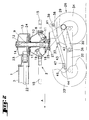
Tel que cela ressort des figures 1 à 3, la machine selon le premier exemple de réalisation comporte un bâti (1) auquel est relié un rotor (2) pour déplacer des végétaux couchés sur le sol. Ce bâti (1) est essentiellement constitué par une poutre creuse (3). Un timon (4) est articulé, au moyen d'un axe (5) sensiblement horizontal, sur l'extrémité avant de la poutre (3). Ce timon (4) permet l'accrochage à un tracteur (non représenté) servant à déplacer la machine dans la direction (A). Un vérin hydraulique de réglage (6) est articulé à la fois sur la poutre (3) et sur un cintre (7) solidaire du timon (4).As shown in Figures 1 to 3, the machine according to the first example embodiment includes a frame (1) to which is connected a rotor (2) for moving plants lying on the ground. This frame (1) is essentially constituted by a hollow beam (3). A drawbar (4) is articulated, by means of an axis (5) substantially horizontal, on the front end of the beam (3). This drawbar (4) allows the attachment to a tractor (not shown) used to move the machine in direction (A). A hydraulic adjustment cylinder (6) is articulated both on the beam (3) and on a hanger (7) integral with the drawbar (4).
Le rotor (2) possède un moyeu (8) en forme de carter. Celui-ci est monté sur un axe central (9) au moyen de roulements (10, 11), de manière à pouvoir tourner autour. Cet axe central (9) est sensiblement vertical ou légèrement incliné dans la direction d'avancement (A). Il est logé dans un palier (12) d'un boítier (13) qui fait partie du bâti (1) et est immobilisé en rotation dans ce palier (13) par une clavette (14). Le moyeu ou carter (8) porte plusieurs bras (15) qui s'étendent dans un plan pratiquement horizontal. Un seul de ces bras (15) est représenté sur la figure 1, afin de préserver la clarté du dessin. Ils sont munis, à leurs extrémités les plus éloignées dudit moyeu ou carter (8), d'outils de travail (16) en forme de fourches de râtelage. Chacun de ces bras (15) est monté dans un palier du moyeu ou carter (8) de manière à pouvoir pivoter sur lui-même, c'est-à-dire autour de son axe géométrique longitudinal. Dans le moyeu ou carter (8) se situe une came de commande (17) qui est fixée sur l'axe central (9). Chaque bras porte-outils (15) possède à son extrémité située à l'intérieur du moyeu ou carter (8), un levier (18) avec un galet (19) qui est guidé dans ladite came (17).The rotor (2) has a hub (8) in the form of a housing. This one is mounted on a central axis (9) by means of bearings (10, 11), so that it can rotate around. This central axis (9) is substantially vertical or slightly inclined in the advancement direction (A). It is housed in a bearing (12) of a housing (13) which part of the frame (1) and is immobilized in rotation in this bearing (13) by a key (14). The hub or casing (8) carries several arms (15) which extend in one plane practically horizontal. Only one of these arms (15) is shown in FIG. 1, in order to preserve the clarity of the drawing. They are provided, at their most remote from said hub or casing (8), working tools (16) in the form of forks raking. Each of these arms (15) is mounted in a bearing of the hub or casing (8) so as to be able to pivot on itself, that is to say around its axis longitudinal geometric. In the hub or housing (8) there is a cam control (17) which is fixed on the central axis (9). Each tool arm (15) has at its end located inside the hub or casing (8), a lever (18) with a roller (19) which is guided in said cam (17).
Le rotor (2) peut être entraíné en rotation sur l'axe central (9) à partir de l'arbre de prise de force du tracteur. A cet effet, la poutre (3) porte à son extrémité avant un carter (20) avec un arbre d'entrée (21) auquel peut être relié un arbre à cardans dont l'autre extrémité est en prise avec ledit arbre de prise de force. Dans la poutre (3) est logé un arbre de transmission (22) qui s'étend du carter (20) jusqu'au rotor (2). Il comporte un pignon (23) qui engrène avec une couronne dentée (24) qui est rendue solidaire du moyeu en forme de carter (8).The rotor (2) can be rotated on the central axis (9) from the tractor PTO shaft. To this end, the beam (3) carries at its end before a housing (20) with an input shaft (21) to which a shaft can be connected gimbals the other end of which is engaged with said PTO shaft. In the beam (3) is housed a transmission shaft (22) which extends from the casing (20) up to the rotor (2). It has a pinion (23) which meshes with a crown toothed (24) which is secured to the housing-shaped hub (8).
L'axe central (9) porte à son extrémité inférieure une embase (25) sur laquelle est vissé un dispositif (26) d'appui au sol. Celui-ci se compose d'une plaque (27) sensiblement horizontale sur laquelle sont soudées deux pattes (28 et 29) qui sont dirigées vers la bas et vers l'arrière et qui portent une traverse (30) avec deux balanciers (31, 32) dont chacun est muni de deux roues porteuses (33 et 34). La traverse (30) est en forme de U. Ses deux extrémités sont dirigées vers l'avant. Sur chacune d'elles est fixé un axe de pivotement (35, 36) sensiblement horizontal. Les balanciers (31, 32) sont montés sur ces axes de pivotement (35, 36) de manière à pouvoir tourner sur eux au moins d'un certain angle. L'une des roues porteuses (33, 34) de chaque balancier (31, 32) se situe à l'avant de l'axe de pivotement (35, 36) correspondant et l'autre à l'arrière de celui-ci. De plus, les deux roues porteuses (33, 34) de chaque balancier (31, 32) sont décalées l'une par rapport à l'autre. Les roues (33) les plus en avant sont situées sur le côté intérieur du balancier (31, 32) correspondant alors que les roues (34) qui sont en arrière se situent sur le côté extérieur du balancier (31, 32) correspondant. Cette disposition permet de rapprocher les roues (33 et 34) au maximum des outils de travail (16), afin de bien leur faire suivre les dénivellations du sol.The central axis (9) carries at its lower end a base (25) on which is screwed a device (26) for supporting the ground. This consists of a substantially horizontal plate (27) on which two legs are welded (28 and 29) which are directed downwards and rearwards and which carry a cross-member (30) with two pendulums (31, 32) each of which is provided with two carrying wheels (33 and 34). The crosspiece (30) is U-shaped. Its two ends are directed towards forward. On each of them is fixed a pivot axis (35, 36) substantially horizontal. The pendulums (31, 32) are mounted on these pivot axes (35, 36) so that you can turn on them at least a certain angle. One of the wheels carriers (33, 34) of each balance (31, 32) is located at the front of the axis of pivot (35, 36) corresponding and the other at the rear thereof. Moreover, the two supporting wheels (33, 34) of each balance (31, 32) are offset one by compared to each other. The foremost wheels (33) are located on the inner side of the corresponding balance (31, 32) while the wheels (34) which are behind are located on the outside of the corresponding pendulum (31, 32). This provision allows the wheels (33 and 34) to be brought as close as possible to the working tools (16), in order to make them follow the unevenness of the ground.
Le dispositif (26) d'appui au sol comprend également un moyen (37) pour déplacer chaque balancier (31, 32) autour de son axe de pivotement (35, 36) et le maintenir dans une position dans laquelle une de ses deux roues porteuses (33, 34) est éloignée du sol. Ce moyen (37) comprend un vérin hydraulique (38). Le corps de celui-ci est articulé avec un axe sensiblement horizontal (39) sur deux flasques (40, 41) qui sont solidaires de la plaque (27) qui est elle-même fixée à l'axe central (9). La tige du vérin hydraulique (38) est articulée avec un axe sensiblement horizontal (42) sur une pièce intermédiaire (43). Cette pièce intermédiaire (43) est sensiblement en forme de V avec deux branches dirigées vers le bas et vers l'avant. Chacune de celles-ci est articulée sur un axe sensiblement horizontal (44) d'une chape (45, 46) solidaire de l'extrémité avant de l'un des balanciers (31, 32). Chaque branche comporte un orifice oblong (47) dans lequel est logé l'axe d'articulation (44) correspondant. La longueur de chaque orifice oblong (47) est telle que les balanciers (31 et 32) puissent pivoter librement avec les roues porteuses (33 et 34) lorsque celles-ci suivent les dénivellations du sol.The device (26) for supporting the ground also comprises means (37) for move each balance (31, 32) around its pivot axis (35, 36) and the maintain in a position in which one of its two carrying wheels (33, 34) is far from the ground. This means (37) comprises a hydraulic cylinder (38). The body thereof is articulated with a substantially horizontal axis (39) on two flanges (40, 41) which are integral with the plate (27) which is itself fixed to the central axis (9). The rod of the hydraulic cylinder (38) is articulated with an axis substantially horizontal (42) on an intermediate piece (43). This intermediate piece (43) is substantially V-shaped with two arms pointing down and forward. Each of these is articulated on a substantially horizontal axis (44) of a yoke (45, 46) secured to the front end of one of the pendulums (31, 32). Each branch has an oblong hole (47) in which the axis is housed corresponding articulation (44). The length of each oblong hole (47) is such that the pendulums (31 and 32) can pivot freely with the wheels carriers (33 and 34) when these follow the unevenness of the ground.
Dans l'exemple de réalisation selon les figures 4 à 6, le bâti (1) et le rotor (2) sont analogues à ceux de l'exemple précité. Pour cette raison leurs pièces constitutives ne sont plus décrites en détail et sont simplement désignées par les mêmes repères. Le dispositif (48) d'appui au sol comprend également une traverse (30) en forme de U qui possède deux axes (35 et 36) sensiblement horizontaux, sur lesquels sont articulés les balanciers (31 et 32) avec les roues porteuses (33 et 34). Cette traverse (30) comporte des oreilles (49) avec un axe d'articulation (50) sensiblement horizontal et transversal à la direction d'avancement (A). Celui-ci est guidé dans deux bras (51, 52) qui sont soudées sur la plaque (27) qui est elle-même vissée sur l'embase (25) de l'axe central (9). La traverse (30) comporte en sus un levier (53) qui est dirigé vers l'avant et vers le haut. Un moyen de déplacement (54) comprend un vérin hydraulique (55) qui est articulé à la fois sur ledit levier (53) au moyen d'un axe (56) et au moyen d'un axe (57) sur deux flasques (58) solidaires de la plaque (27) et dont l'un se situe à droite et l'autre à gauche dudit vérin hydraulique (55). Les axes d'articulation (50, 56 et 57) sont sensiblement parallèles entre eux. Le moyen de déplacement (54) comporte en sus une barre transversale (59) qui est fixée à la plaque (27) et qui est munie à chaque extrémité d'un axe d'articulation (60, 61) dirigé latéralement. Sur chacun de ces axes (60, 61) est montée une extrémité d'une tige de retenue (62, 63). L'autre extrémité de chaque tige (62, 63) est articulée sur un axe (64) d'une chape (65, 66) prévue sur chaque balancier (31, 32). Chaque chape (65, 66) se situe près de l'extrémité avant du balancier (31, 32) correspondant. Chaque tige de retenue (62, 63) comporte un orifice oblong (67) à travers lequel passe l'axe (64) correspondant. La longueur des orifices oblongs (67) est telle que les balanciers (31, 32) puissent pivoter librement autour des axes (35, 36) en suivant les dénivellations du sol. Les axes d'articulation (60, 61, 64) des tiges de retenue (62, 63) sont sensiblement horizontaux et transversaux à la direction d'avancement (A). In the embodiment according to Figures 4 to 6, the frame (1) and the rotor (2) are similar to those of the above example. For this reason their parts are no longer described in detail and are simply denoted by the same benchmarks. The ground support device (48) also includes a U-shaped crosspiece (30) which has two axes (35 and 36) substantially horizontal, on which the pendulums (31 and 32) are articulated with the wheels carriers (33 and 34). This crosspiece (30) has ears (49) with an axis articulation (50) substantially horizontal and transverse to the direction progress (A). This is guided in two arms (51, 52) which are welded on the plate (27) which is itself screwed onto the base (25) of the central axis (9). The crosspiece (30) additionally comprises a lever (53) which is directed towards the front and towards the high. A displacement means (54) includes a hydraulic cylinder (55) which is articulated both on said lever (53) by means of an axis (56) and by means of an axis (57) on two flanges (58) integral with the plate (27) and one of which is located on the right and the other to the left of said hydraulic cylinder (55). The axes of articulation (50, 56 and 57) are substantially parallel to each other. Means of transport (54) additionally comprises a transverse bar (59) which is fixed to the plate (27) and which is provided at each end with a hinge pin (60, 61) directed laterally. Sure each of these axes (60, 61) is mounted one end of a retaining rod (62, 63). The other end of each rod (62, 63) is articulated on an axis (64) of a yoke (65, 66) provided on each balance (31, 32). Each yoke (65, 66) is located near the front end of the corresponding pendulum (31, 32). Each rod of retainer (62, 63) has an oblong orifice (67) through which the axis (64) passes corresponding. The length of the oblong holes (67) is such that the pendulums (31, 32) can pivot freely around the axes (35, 36) following the uneven ground. The articulation axes (60, 61, 64) of the retaining rods (62, 63) are substantially horizontal and transverse to the direction of advance (A).
La machine selon l'exemple de réalisation des figures 7 et 8 comporte un bâti (1) avec deux rotors (2, 2'). Ceux-ci sont semblables au rotor (2) de l'exemple selon les figures 4 à 6 et ne sont plus décrits en détail. Le bâti (1) se compose essentiellement de deux poutres creuses (68 et 69). La première poutre (68) est liée à l'axe central (9) du premier rotor (2) au moyen d'un coude (70). Elle porte à son extrémité la plus en avant un timon (71) et un vérin hydraulique (72) pour le réglage de la position dudit timon (71). La deuxième poutre (69) est réalisée en deux parties (73 et 74) articulées entre elles au moyen d'un axe (75) sensiblement horizontal. La partie avant (73) est liée à l'axe central (9) du rotor (2) de telle sorte qu'elle puisse tourner autour. La partie arrière (74) est liée au rotor (2'), l'axe central (9') de ce dernier pouvant tourner par rapport à la partie arrière (74) et pouvant être immobilisé dans diverses positions. Cela permet d'amener le rotor arrière (2') dans différentes positions par rapport au rotor avant (2). L'entraínement en rotation de ces rotors (2 et 2') est assuré au moyen d'arbres de transmission situés dans les poutres (68 et 69).The machine according to the embodiment of Figures 7 and 8 comprises a frame (1) with two rotors (2, 2 '). These are similar to the rotor (2) in the example according to Figures 4 to 6 and are no longer described in detail. The frame (1) consists essentially two hollow beams (68 and 69). The first beam (68) is linked to the central axis (9) of the first rotor (2) by means of an elbow (70). It brings to its foremost end a drawbar (71) and a hydraulic cylinder (72) for the adjusting the position of said drawbar (71). The second beam (69) is made in two parts (73 and 74) hinged together by means of an axis (75) substantially horizontal. The front part (73) is linked to the central axis (9) of the rotor (2) so that that she can turn around. The rear part (74) is linked to the rotor (2 '), the axis central (9 ') of the latter which can rotate relative to the rear part (74) and can be immobilized in various positions. This brings the rotor rear (2 ') in different positions relative to the front rotor (2). training in rotation of these rotors (2 and 2 ') is ensured by means of transmission shafts located in the beams (68 and 69).
La machine selon l'exemple représenté sur la figure 9 comporte un bâti (1) composé essentiellement par une poutre longitudinale (76) munie d'un dispositif d'accouplement à un tracteur et par une poutre transversale (77). Celle-ci peut être réalisée en une ou plusieurs parties et porte plusieurs rotors (78) disposés l'un à côté de l'autre.The machine according to the example shown in Figure 9 has a frame (1) composed essentially by a longitudinal beam (76) provided with a device coupling to a tractor and by a transverse beam (77). This can be made in one or more parts and carries several rotors (78) arranged one to next to each other.
Chacun de ces rotors (78) possède un moyeu (79) en forme d'assiette qui est monté sur un axe central (80) de manière à pouvoir tourner autour. Cet axe est logé dans un palier (81) d'un boítier (82) qui est solidaire de la poutre transversale (77). Il est légèrement incliné dans la direction d'avancement (A). Entre la poutre longitudinale (76) et la poutre transversale (77) est disposée une manivelle (83) qui permet de déplacer ladite poutre transversale (77) autour d'un axe d'articulation (84) en vue de modifier l'inclinaison des axes (80) de tous les rotors (78). Le moyeu (79) de chaque rotor (78) possède plusieurs bras (85) qui s'étendent plus ou moins radialement et qui possèdent à leurs extrémités extérieures des outils de travail (86) en forme de fourches.Each of these rotors (78) has a plate-shaped hub (79) which is mounted on a central axis (80) so that it can rotate around. This axis is housed in a bearing (81) of a housing (82) which is integral with the transverse beam (77). It is slightly inclined in the direction of travel (A). Between the beam longitudinal (76) and the transverse beam (77) is arranged a crank (83) which allows said transverse beam (77) to be displaced about an axis of articulation (84) in order to modify the inclination of the axes (80) of all the rotors (78). The hub (79) of each rotor (78) has several arms (85) which extend more or less radially and which have at their ends outside of the working tools (86) in the form of forks.
L'extrémité inférieure de chaque axe central (80) est munie d'un dispositif (87) d'appui au sol. Celui-ci se compose d'un balancier (88) articulé sur un axe transversal (89) qui est solidaire de l'axe central (80). Le balancier (88) comporte deux roues porteuses (90 et 91) dont l'une se situe à l'avant et l'autre à l'arrière de l'axe transversal (89). Ledit dispositif (87) d'appui au sol comprend un moyen (92) pour déplacer le balancier (88) et le maintenir dans une position dans laquelle la roue porteuse (90) est éloignée du sol en vue du transport. Ce moyen (92) est constitué par un vérin hydraulique (93) qui est articulé au moyen d'un axe (98) sur un raccord (94) solidaire de l'axe central (80) et sur le balancier (88). Ce dernier comporte près de son extrémité avant une chape (95) avec un orifice oblong (96). Un axe d'articulation (97) qui est solidaire du vérin hydraulique (93) est logé dans ledit orifice oblong (96), ce qui permet au balancier (88) de pivoter autour de son axe d'articulation (89) lorsque les roues porteuses (90 et 91) passent sur des dénivellations. Des arbres de transmission (99) sont logés dans la poutre transversale (77) en vue de l'entraínement en rotation des rotors (78).The lower end of each central axis (80) is provided with a device (87) ground support. This consists of a balance (88) articulated on an axis transverse (89) which is integral with the central axis (80). The pendulum (88) has two carrying wheels (90 and 91), one of which is located at the front and the other at the rear of the transverse axis (89). Said device (87) for supporting the ground comprises means (92) to move the pendulum (88) and hold it in a position in which the load-bearing wheel (90) is moved away from the ground for transport. This means (92) is constituted by a hydraulic cylinder (93) which is articulated by means of an axis (98) on a fitting (94) integral with the central axis (80) and on the balance (88). This last comprises near its front end a yoke (95) with an oblong orifice (96). A hinge pin (97) which is integral with the hydraulic cylinder (93) is housed in said oblong orifice (96), which allows the pendulum (88) to pivot around its hinge pin (89) when the supporting wheels (90 and 91) pass over inclines. Transmission shafts (99) are housed in the beam transverse (77) for the rotational drive of the rotors (78).
Au travail, l'andaineur selon les figures 1 à 3 est déplacé dans la direction (A) à l'aide d'un tracteur. Le rotor (2) est alors entraíné en rotation dans le sens (F) autour de l'axe central (9) à partir de l'arbre de prise de force dudit tracteur. Durant cette rotation, la came (17) commande les bras porte-outils (15), par l'intermédiaire des leviers (18) et des galets (19), de telle sorte qu'ils déplacent leurs outils de travail (16). Ainsi, sur la partie avant de leur trajectoire, ces outils (16) sont sensiblement verticaux et ramassent les produits se trouvant sur le sol. Ensuite, sur la partie latérale de leur trajectoire, les outils (16) sont relevés de sorte qu'ils déposent les produits ramassés sous la forme d'un andain. Enfin, sur la partie arrière de leur trajectoire, ils reviennent progressivement dans la position pour ramasser.At work, the swather according to Figures 1 to 3 is moved in the direction (A) using a tractor. The rotor (2) is then rotated in the direction (F) around the central axis (9) from the PTO shaft of said tractor. During this rotation, the cam (17) controls the tool-carrying arms (15), by through the levers (18) and the rollers (19), so that they move their working tools (16). So, on the front part of their trajectory, these tools (16) are substantially vertical and collect the products lying on the ground. Then, on the lateral part of their trajectory, the tools (16) are raised so they deposit the products collected in the form of a swath. Finally, on the part back of their trajectory, they gradually return to the position for to pick up.
Durant ce travail, toutes les roues porteuses (33 et 34) roulent sur le sol. Le vérin hydraulique (38) est allongé et l'axe d'articulation (44) de la chape (45, 46) de chaque balancier (31, 32) se situe sensiblement au milieu des orifices oblongs (47) de la pièce intermédiaire (43). Lorsque les roues porteuses (33 et 34) passent sur des bosses ou dans des creux, elles pivotent avec le balancier (31, 32) correspondant autour de l'axe d'articulation (35, 36) de ce dernier avec la traverse (30). Les déplacements en hauteur des roues (33 et 34) sont alors plus importants que les déplacements du balancier (31, 32) correspondant au niveau de son axe d'articulation (35, 36). De ce fait, des déplacements de la traverse (30) et par conséquent de tout le rotor (2) demeurent relativement faibles. Celui-ci est ainsi beaucoup plus stable et il peut avancer à plus grande vitesse.During this work, all the load wheels (33 and 34) roll on the ground. The hydraulic cylinder (38) is elongated and the hinge pin (44) of the yoke (45, 46) of each balance (31, 32) is located substantially in the middle of the oblong holes (47) of the intermediate piece (43). When the load wheels (33 and 34) pass on bumps or in recesses, they pivot with the balance (31, 32) corresponding around the axis of articulation (35, 36) of the latter with the crosspiece (30). The height displacements of the wheels (33 and 34) are then greater that the movements of the pendulum (31, 32) corresponding to the level of its axis articulation (35, 36). Therefore, displacements of the crosspiece (30) and by Therefore the entire rotor (2) remains relatively small. This is so much more stable and it can move faster.
Pour le transport, l'entraínement en rotation du rotor (2) est coupé. Les vérins hydrauliques (6 et 38) sont actionnés depuis le tracteur. Le vérin hydraulique (38) se rétracte et tire la pièce intermédiaire (43) vers l'arrière. Celle-ci fait tourner les balanciers (31, 32) autour des axes de pivotement (35, 36) dans une position oblique par rapport au sol (voir figure 3). Dans cette position, les roues porteuses avant (33) sont éloignées du sol. Le rotor (2) est soulevé et ses outils de travail (16) sont éloignés du sol. Il ne repose alors plus sur le sol que par l'intermédiaire de deux roues arrière (34). Enfin, le vérin hydraulique (6) s'allonge et fait pivoter l'avant du bâti (1) par rapport au timon (4) de sorte que le rotor (2) soit sensiblement horizontal. Ainsi, les outils de travail (16) n'accrochent pas les obstacles qui peuvent se trouver sur le sol et les roues porteuses (34) ne ripent pas sur le sol dans les virages.For transport, the rotational drive of the rotor (2) is cut. The cylinders hydraulics (6 and 38) are operated from the tractor. The hydraulic cylinder (38) retracts and pulls the intermediate piece (43) backwards. This turns the pendulums (31, 32) around the pivot axes (35, 36) in a position oblique to the ground (see Figure 3). In this position, the carrying wheels front (33) are remote from the ground. The rotor (2) is raised and its working tools (16) are far from the ground. It then only rests on the ground through two rear wheels (34). Finally, the hydraulic cylinder (6) lengthens and rotates the front of the frame (1) relative to the drawbar (4) so that the rotor (2) is substantially horizontal. Thus, the working tools (16) do not catch the obstacles that may be on the ground and the load wheels (34) do not respond on the ground in turns.
Pour revenir dans la position de travail, les vérins hydrauliques (6 et 38) sont commandés pour qu'ils se déplacent en sens inverses et l'entraínement en rotation du rotor (2) est rétabli.To return to the working position, the hydraulic cylinders (6 and 38) are controlled so that they move in opposite directions and the rotational drive rotor (2) is restored.
L'andaineur selon l'exemple des figures 4 à 6 travaille de la même manière que celui représenté sur les figures 1 à 3. Comme cela ressort plus particulièrement de la figure 5, le vérin hydraulique (55) est rétracté dans la position de travail. Lorsque les balanciers (31 et 32) sont en position horizontale, les axes d'articulations (64) de leurs chapes (65 et 66) se situent au milieu des orifices oblongs (67) des tiges de retenue (62 et 63). Lesdits balanciers (31 et 32) peuvent ainsi pivoter autour de leurs axes (35 et 36) sur la traverse (30), lorsque les roues porteuses (33 et 34) rencontrent des dénivellations.The rake according to the example in Figures 4 to 6 works in the same way than that shown in Figures 1 to 3. As can be seen more particularly from Figure 5, the hydraulic cylinder (55) is retracted into the working position. When the pendulums (31 and 32) are in a horizontal position, the axes of articulations (64) of their yokes (65 and 66) are located in the middle of the oblong holes (67) of the retaining rods (62 and 63). Said pendulums (31 and 32) can thus pivot around their axes (35 and 36) on the crosspiece (30), when the carrying wheels (33 and 34) meet unevennesses.
Pour mettre la machine en position de transport, le vérin hydraulique (55) du dispositif (48) d'appui au sol est commandé pour qu'il s'allonge. Le levier (53) pousse la traverse (30) vers le bas, ce qui a pour effet de soulever tout le rotor (2) par pivotement autour de l'axe d'articulation (50). La barre transversale (59) tire alors les tiges de retenues (62 et 63) vers le haut. Celles-ci entraínent les balanciers (31 et 32) et les font pivoter autour de leurs axes de pivotement (35 et 36), dans une position oblique par rapport au sol. Les roues avant (33) sont alors éloignées du sol et seules les roues arrière (34) reposent sur celui-ci. Simultanément, le vérin hydraulique (6) est actionné pour qu'il s'allonge et fasse pivoter l'avant du bâti (1) par rapport au timon (4) de telle sorte que le rotor (2) soit sensiblement horizontal.To put the machine in the transport position, the hydraulic cylinder (55) of the device (48) for supporting the ground is controlled so that it lengthens. The lever (53) pushes the crossbar (30) down, which raises the whole rotor (2) by pivoting about the articulation axis (50). The crossbar (59) pulls then the retaining rods (62 and 63) upwards. These drive the pendulums (31 and 32) and rotate them around their pivot axes (35 and 36), in an oblique position relative to the ground. The front wheels (33) are then distant from the ground and only the rear wheels (34) rest thereon. Simultaneously, the hydraulic cylinder (6) is actuated so that it lengthens and makes pivot the front of the frame (1) relative to the drawbar (4) so that the rotor (2) is substantially horizontal.
Dans ce cas, le pivotement relatif entre la traverse (30) et le rotor (2) ainsi que le pivotement des balanciers (31 et 32) provoquent un important soulèvement dudit rotor (2). Ses outils de travail (16) sont alors très éloignés du sol.In this case, the relative pivoting between the crosspiece (30) and the rotor (2) thus that the pivoting of the pendulums (31 and 32) cause a significant lifting of said rotor (2). Its working tools (16) are then very far from the ground.
Pour remettre la machine en position de travail les sens de déplacement des vérins hydrauliques (55 et 6) sont inversés de sorte que le rotor (2) se rapproche du sol. Ensuite, l'entraínement en rotation du rotor (2) est rétabli.To return the machine to the working position, the directions of movement of the hydraulic cylinders (55 and 6) are inverted so that the rotor (2) approaches of the ground. Then, the rotational drive of the rotor (2) is restored.
Le mode de travail des rotors (2 et 2') de l'andaineur selon les figures 7 et 8 est pareil que celui qui est décrit en liaison avec le rotor (2) de l'andaineur représenté sur les figures 1 à 3. De plus, le deuxième rotor (2') peut être déplacé latéralement, autour de l'axe central (9) du premier rotor (2). Il peut ainsi être transposé dans une position telle que chaque rotor (2 et 2') forme son propre andain ou dans une position où le second rotor (2') reprend l'andain déposé par le premier rotor (2) et assure la formation d'un andain de plus grand volume.The working mode of the rotors (2 and 2 ') of the swather according to Figures 7 and 8 is the same as that described in connection with the rotor (2) of the rake shown in Figures 1 to 3. In addition, the second rotor (2 ') can be moved laterally, around the central axis (9) of the first rotor (2). It can thus be transposed in a position such that each rotor (2 and 2 ') forms its own swath or in a position where the second rotor (2 ') takes up the swath deposited by the first rotor (2) and ensures the formation of a swath of greater volume.
Pour le transport (figure 8), l'entraínement en rotation est arrêté et le second rotor (2') est ramené dans le sillage du premier rotor (2) afin de réduire la largeur de l'ensemble. Ensuite, les deux rotors (2 et 2') sont soulevés par les vérins hydrauliques (55 et 55') et les tiges de retenue (62, 63 et 62', 63') de la manière qui a été décrite précédemment en liaison avec le rotor (2) de l'exemple selon les figures 4 à 6. Enfin, le vérin hydraulique (72) est actionné pour qu'il s'allonge. Il ramène ainsi la partie avant du bâti (1) et le rotor (2) en position horizontale.For transport (Figure 8), the rotational drive is stopped and the second rotor (2 ') is brought back in the wake of the first rotor (2) in order to reduce the width from the whole. Then the two rotors (2 and 2 ') are lifted by the cylinders hydraulic (55 and 55 ') and the retaining rods (62, 63 and 62', 63 ') in the manner that has been described previously in connection with the rotor (2) of the example according to the Figures 4 to 6. Finally, the hydraulic cylinder (72) is actuated so that it lengthens. he thus brings the front part of the frame (1) and the rotor (2) into a horizontal position.
La machine est alors portée par les seules roues arrière (34 et 34') des deux rotors (2 et 2'). Dans cette position, la distance entre les outils de travail (16 et 16') et le sol est très importante et les roues (34 et 34') ne ripent pas sur le sol dans les virages.The machine is then carried by the only rear wheels (34 and 34 ') of the two rotors (2 and 2 '). In this position, the distance between the working tools (16 and 16 ') and the ground is very important and the wheels (34 and 34 ') do not rip on the ground in the turns.
Pour revenir en position de travail, l'opérateur procède de la manière inverse.To return to the working position, the operator proceeds in the reverse manner.
La faneuse selon la figure 9 est également déplacée dans la direction (A) au moyen d'un tracteur durant le travail. Les rotors (78) sont entraínés en rotation depuis le tracteur, autour de leurs axes centraux (80) respectifs, de telle sorte qu'ils tournent deux à deux en convergence à l'avant. Lors de cette rotation, leurs outils de travail (86) ramassent les végétaux qui se trouvent au sol, les déplacent vers l'arrière entre les rotors (78) convergents et les étalent à nouveau derrière la machine tout en provoquant leur retournement. Les roues porteuses (90 et 91) roulent sur le sol. En position horizontale, l'axe d'articulation (97) du vérin hydraulique (93) avec la chape (95) du balancier (88) de chaque rotor (78) se situe au milieu de l'orifice oblong (96) de ladite chape (95). Les roues porteuses (90 et 91) et le balancier (88) peuvent ainsi se déplacer vers le haut et vers le bas autour de l'axe de pivotement (89) pour suivre les dénivellations du sol.The tedder according to figure 9 is also moved in direction (A) at using a tractor during work. The rotors (78) are rotated from the tractor, around their respective central axes (80), so that they turn two by two in convergence at the front. During this rotation, their tools work (86) pick up the plants on the ground, move them to the rear between the converging rotors (78) and spread them again behind the machine while causing them to overturn. The load wheels (90 and 91) roll on the ground. In horizontal position, the hinge pin (97) of the cylinder hydraulic (93) with the yoke (95) of the balance (88) of each rotor (78) is located in the middle of the oblong hole (96) of said yoke (95). The load wheels (90 and 91) and the pendulum (88) can thus move up and down around pivot axis (89) to follow the unevenness of the ground.
Pour le transport, l'entraínement en rotation des rotors (78) est coupé. Le vérin hydraulique (93) sous chaque rotor (78) de la machine est actionné de sorte qu'il se rétracte. Il tire alors sur le balancier (88) et le déplace autour de son axe de pivotement (89) dans une position oblique dans laquelle la roue avant (90) est éloignée du sol. La machine ne repose alors plus que sur les roues arrière (91) qui sont toutes situées sur une même ligne et ne ripent pas sur le sol dans les virages. Tous les rotors (78) sont soulevés de telle sorte que leurs outils de travail (86) soient éloignés du sol. Enfin, lesdits rotors (78) peuvent être amenés dans une position horizontale au moyen de la manivelle (83).For transport, the rotational drive of the rotors (78) is cut. The hydraulic cylinder (93) under each rotor (78) of the machine is actuated so that it retracts. He then pulls on the pendulum (88) and moves it around its axis of pivot (89) in an oblique position in which the front wheel (90) is far from the ground. The machine then only rests on the rear wheels (91) which are all on the same line and do not hit the ground when cornering. All the rotors (78) are lifted so that their working tools (86) are far from the ground. Finally, said rotors (78) can be brought into a horizontal position using the crank (83).
Pour revenir en position de travail, la manivelle (83) et les vérins hydrauliques (93) sont actionnés en sens inverses.To return to the working position, the crank (83) and the jacks hydraulics (93) are operated in opposite directions.
Il est bien évident que l'invention n'est pas limitée aux modes de réalisation décrits ci-dessus et représentés sur les dessins annexés. Des modifications restent possibles, notamment en ce qui concerne la constitution des divers éléments ou par substitution d'équivalents techniques, sans pour autant sortir du domaine de protection tel que défini dans les revendications.It is obvious that the invention is not limited to the embodiments described above and shown in the accompanying drawings. Changes remain possible, in particular as regards the constitution of the various elements or by substitution of technical equivalents, without departing from the scope of protection as defined in the claims.
Claims (10)
- Haymaking machine comprising a frame (1) connected to at least one rotor (2, 2', 78) for moving plant matter on the ground, which rotor (2, 2', 78) has a hub (8, 8', 79) which is fitted with tool-carrier arms (15, 15', 85) and which is mounted on a central axis (9, 9', 80) that is substantially vertical or inclined in the direction of forward travel (A) so as to be able to rotate thereon, the said axis (9, 9', 80) being connected to the frame (1) and comprising at its lower end a device (26, 48, 48', 87') for resting on the ground, including at least one balance beam (31, 31', 32, 32', 88) which is mounted on a substantially horizontal pivot axis (35, 35', 36, 36', 89) and which is equipped with two carrier wheels (33, 33', 34, 34', 90, 91) which run over the ground during work, characterized in that the device (26, 48, 48', 87) for resting on the ground comprises a means (37, 54, 54', 92) for moving the or each balance beam (31, 31', 32, 32', 88) about its pivot axis (35, 36, 35', 36', 89) into an oblique position in which one of its two carrier wheels (33, 33', 34, 34', 90, 91) and the rotor (2, 2', 78) with its working tools (16) are away from the ground with a view to transport.
- Machine according to Claim 1, characterized in that the means (37, 54, 54', 92) of moving each balance beam (31, 31', 32, 32', 88) comprises at least one hydraulic ram (38, 55, 55', 93).
- Machine according to Claim 2, characterized in that the hydraulic ram (93) is articulated to a coupling (94) secured to the central axis (80) and to the corresponding balance beam (88).
- Machine according to Claim 3, characterized in that the balance beam (88) comprises a jaw (95) with an oblong orifice (96) in which an axis of articulation (97) of the hydraulic ram (93) is housed.
- Machine according to Claim 2, characterized in that the hydraulic ram (38) is articulated to plates (40, 41) connected to the central axis (9) and to an intermediate piece (43) which is itself articulated to each balance beam (31, 32).
- Machine according to Claim 5, characterized in that each balance beam (31, 32) comprises a jaw (45, 46) with an axis of articulation (44) and in that the intermediate piece (43) comprises, at each end, an oblong orifice (47) in which the said axis (44) is situated.
- Machine according to Claim 1, characterized in that the device (48, 48') for resting on the ground comprises a crossbeam (30, 30') which has at least one axis (35, 35', 36, 36') to which a balance beam (31, 31', 32, 32') is articulated, which crossbeam (30, 30') is articulated with respect to the central axis (9, 9') of the corresponding rotor (2, 2') with the aid of a substantially horizontal axis (50, 50') and in that the means (54, 54') consists of a hydraulic ram (55, 55') which is articulated to plates (58) connected to the central axis (9, 9') and to a lever (53, 53') of the crossbeam (30, 30') and by a retaining rod (62, 62', 63, 63') for each balance beam (31,31', 32, 32').
- Machine according to Claim 7, characterized in that each retaining rod (62, 62', 63, 63') is articulated to a transverse bar (59, 59') connected to the central axis (9, 9') and in a jaw (65, 65', 66, 66') of the corresponding balance beam (31, 31', 32,32').
- Machine according to Claim 8, characterized in that the jaw (65, 65', 66, 66') is situated near the front end of the corresponding balance beam (31, 31', 32, 32').
- Machine according to Claim 8, characterized in that each retaining rod (62, 62', 63, 63') has an oblong orifice (67, 67') and in that the corresponding jaw (65, 65', 66, 66') has an axis (64, 64') which passes through the said oblong orifice (67, 67').
Applications Claiming Priority (2)
| Application Number | Priority Date | Filing Date | Title |
|---|---|---|---|
| FR9701710 | 1997-02-11 | ||
| FR9701710A FR2759245B1 (en) | 1997-02-11 | 1997-02-11 | FENAISON MACHINE WITH A GROUND SUPPORT DEVICE INCLUDING AT LEAST A BALANCER WITH TWO CARRIER WHEELS AND A MEANS FOR MOVING THIS BALANCER FOR TRANSPORT |
Publications (2)
| Publication Number | Publication Date |
|---|---|
| EP0857413A1 EP0857413A1 (en) | 1998-08-12 |
| EP0857413B1 true EP0857413B1 (en) | 2003-04-16 |
Family
ID=9503695
Family Applications (1)
| Application Number | Title | Priority Date | Filing Date |
|---|---|---|---|
| EP98440014A Expired - Lifetime EP0857413B1 (en) | 1997-02-11 | 1998-02-04 | Haymaking machine |
Country Status (5)
| Country | Link |
|---|---|
| EP (1) | EP0857413B1 (en) |
| AT (1) | ATE237217T1 (en) |
| DE (1) | DE69813336T2 (en) |
| DK (1) | DK0857413T3 (en) |
| FR (1) | FR2759245B1 (en) |
Cited By (1)
| Publication number | Priority date | Publication date | Assignee | Title |
|---|---|---|---|---|
| NL1029351C2 (en) | 2005-06-28 | 2007-01-02 | Lely Entpr Ag | Haymaking machine and machine. |
Families Citing this family (5)
| Publication number | Priority date | Publication date | Assignee | Title |
|---|---|---|---|---|
| FR2798817B1 (en) * | 1999-09-23 | 2002-05-31 | Kuhn Sa | FENAISON MACHINE, PARTICULARLY A SWATHER WITH SEVERAL ROTORS BASED ON THE GROUND BY CARRYING WHEELS |
| DE19952555C2 (en) * | 1999-11-01 | 2003-08-07 | Krone Bernhard Gmbh Maschf | Hay-making machine |
| DE10006737A1 (en) * | 2000-02-15 | 2001-08-16 | Claas Saulgau Gmbh | Agricultural work machine |
| FR2881023B1 (en) * | 2005-01-26 | 2008-07-04 | Gyrland Ind Sas Soc Par Action | ROTOR OF ANDAINEUR |
| DE202018106264U1 (en) * | 2018-11-02 | 2018-11-19 | Pöttinger Landtechnik Gmbh | Agricultural implement |
Family Cites Families (9)
| Publication number | Priority date | Publication date | Assignee | Title |
|---|---|---|---|---|
| DE2002746C3 (en) * | 1970-01-22 | 1978-08-03 | Fella-Werke Gmbh, 8501 Feucht | Haymaking machine |
| DE2004349A1 (en) * | 1970-01-30 | 1971-08-05 | Fella Werke GmbH, 8501 Feucht | Haymaking machine |
| DE8811010U1 (en) * | 1988-03-17 | 1988-10-27 | Claas Saulgau Gmbh, 7968 Saulgau, De | |
| DE3926382A1 (en) * | 1989-08-10 | 1991-02-14 | Fella Werke Gmbh | Folding agricultural haymaking machine - incorporates tilting frame connected to pole for attachment to tractor |
| DE4015767A1 (en) * | 1990-05-16 | 1991-11-21 | Poettinger Alois Landmasch | HAY ADVERTISING MACHINE |
| DE4122072C2 (en) * | 1991-07-04 | 2003-07-31 | Claas Saulgau Gmbh | Chassis for rotary hay machines, such as rotary swathers |
| FR2702336B1 (en) * | 1993-03-12 | 1995-05-05 | Kuhn Sa | Advanced haymaking machine. |
| FR2705861B1 (en) * | 1993-06-04 | 1995-08-18 | Kuhn Sa | Haymaking machine with a movable transport device. |
| DE4321128C2 (en) * | 1993-06-25 | 2002-08-08 | Claas Saulgau Gmbh | Freely swiveling trailing wheels for agricultural machines, especially rotary hay machines |
-
1997
- 1997-02-11 FR FR9701710A patent/FR2759245B1/en not_active Expired - Fee Related
-
1998
- 1998-02-04 DE DE69813336T patent/DE69813336T2/en not_active Expired - Lifetime
- 1998-02-04 DK DK98440014T patent/DK0857413T3/en active
- 1998-02-04 AT AT98440014T patent/ATE237217T1/en active
- 1998-02-04 EP EP98440014A patent/EP0857413B1/en not_active Expired - Lifetime
Cited By (3)
| Publication number | Priority date | Publication date | Assignee | Title |
|---|---|---|---|---|
| NL1029351C2 (en) | 2005-06-28 | 2007-01-02 | Lely Entpr Ag | Haymaking machine and machine. |
| EP1738635A1 (en) | 2005-06-28 | 2007-01-03 | Lely Enterprises AG | A haymaking machine and a machine |
| US7398983B2 (en) | 2005-06-28 | 2008-07-15 | Lely Enterprises Ag | Haymaking machine and a machine |
Also Published As
| Publication number | Publication date |
|---|---|
| FR2759245A1 (en) | 1998-08-14 |
| FR2759245B1 (en) | 1999-04-23 |
| ATE237217T1 (en) | 2003-05-15 |
| DE69813336D1 (en) | 2003-05-22 |
| EP0857413A1 (en) | 1998-08-12 |
| DE69813336T2 (en) | 2004-02-05 |
| DK0857413T3 (en) | 2003-07-21 |
Similar Documents
| Publication | Publication Date | Title |
|---|---|---|
| EP1366650B1 (en) | Agricultural implement comprising a transporting device | |
| FR2691041A1 (en) | Cutting machine, especially mower, easily adapting to the relief of the ground. | |
| CA2833103A1 (en) | Agricultural machine with improved folding device | |
| EP0318407A1 (en) | Haymaking machine with at least one raking wheel equipped with controlled tool-carrying arms | |
| EP1290936B1 (en) | Haymaking machine | |
| FR2631208A1 (en) | IMPROVING AGRICULTURAL MACHINERY WITH AN ARTICULATED TOOL HOLDER CHASSIS | |
| EP0772969B1 (en) | Haymaking machine with at least one windrowing rotor | |
| FR2736503A1 (en) | AGRICULTURAL MACHINE, PARTICULARLY TEDDER WITH MULTIPLE ROTARY RAKES | |
| EP0514302B1 (en) | Improved crop windrower | |
| EP0857413B1 (en) | Haymaking machine | |
| EP0692185B1 (en) | Haymaking machine, especially a swather with controlled fork-carrying arms | |
| EP1076482B1 (en) | Hay harvesting machine provided with at least a swathing rotor equipped with a deflector with adjustable position | |
| EP0797913B1 (en) | Haymaking machine | |
| EP0554200B1 (en) | Haymaking machine comprising a frame with controlled support wheels | |
| EP1926363A2 (en) | Haying machine with foldable lateral structures | |
| FR2534110A1 (en) | DEVICE FOR SUPPORTING, AT LEAST PARTIALLY, THE WEIGHT OF AN AGRICULTURAL MACHINE | |
| FR2707450A1 (en) | Hay-making machine with tedding or windrowing rotors equipped with wheels for resting on the ground | |
| EP0733302B1 (en) | Haymaking machine | |
| EP0914766B1 (en) | Haymaking machine | |
| EP1013161B1 (en) | Haymaking machine | |
| FR2798817A1 (en) | Swathing machine, for hay making, consists of primary and secondary beams with rotors, with rotors supported by wheels mounted on transverse beams carried by support axis mounted beneath swathing rotors | |
| EP4272538A1 (en) | Secured haymaking machine and related process | |
| FR3114479A1 (en) | Trailed agricultural harvesting machine with an adjustable axle | |
| FR2699044A1 (en) | Haymaking machine with displaceable wheels - comprises wheel arm carriers connected to pivoting axle with hydraulic actuator operated rack and pinion | |
| FR2683697A1 (en) | Device for transporting agricultural machinery |
Legal Events
| Date | Code | Title | Description |
|---|---|---|---|
| PUAI | Public reference made under article 153(3) epc to a published international application that has entered the european phase |
Free format text: ORIGINAL CODE: 0009012 |
|
| AK | Designated contracting states |
Kind code of ref document: A1 Designated state(s): AT DE DK FR IT NL |
|
| AX | Request for extension of the european patent |
Free format text: AL;LT;LV;MK;RO;SI |
|
| 17P | Request for examination filed |
Effective date: 19990125 |
|
| AKX | Designation fees paid |
Free format text: AT DE DK FR IT NL |
|
| RBV | Designated contracting states (corrected) |
Designated state(s): AT DE DK FR IT NL |
|
| 17Q | First examination report despatched |
Effective date: 20020117 |
|
| GRAH | Despatch of communication of intention to grant a patent |
Free format text: ORIGINAL CODE: EPIDOS IGRA |
|
| GRAH | Despatch of communication of intention to grant a patent |
Free format text: ORIGINAL CODE: EPIDOS IGRA |
|
| GRAA | (expected) grant |
Free format text: ORIGINAL CODE: 0009210 |
|
| AK | Designated contracting states |
Designated state(s): AT DE DK FR IT NL |
|
| REF | Corresponds to: |
Ref document number: 69813336 Country of ref document: DE Date of ref document: 20030522 Kind code of ref document: P |
|
| REG | Reference to a national code |
Ref country code: DK Ref legal event code: T3 |
|
| PLBE | No opposition filed within time limit |
Free format text: ORIGINAL CODE: 0009261 |
|
| STAA | Information on the status of an ep patent application or granted ep patent |
Free format text: STATUS: NO OPPOSITION FILED WITHIN TIME LIMIT |
|
| 26N | No opposition filed |
Effective date: 20040119 |
|
| PGFP | Annual fee paid to national office [announced via postgrant information from national office to epo] |
Ref country code: NL Payment date: 20150126 Year of fee payment: 18 |
|
| PGFP | Annual fee paid to national office [announced via postgrant information from national office to epo] |
Ref country code: DK Payment date: 20150122 Year of fee payment: 18 Ref country code: IT Payment date: 20150128 Year of fee payment: 18 |
|
| PGFP | Annual fee paid to national office [announced via postgrant information from national office to epo] |
Ref country code: AT Payment date: 20150122 Year of fee payment: 18 |
|
| REG | Reference to a national code |
Ref country code: FR Ref legal event code: PLFP Year of fee payment: 19 |
|
| PGFP | Annual fee paid to national office [announced via postgrant information from national office to epo] |
Ref country code: DE Payment date: 20160121 Year of fee payment: 19 |
|
| PGFP | Annual fee paid to national office [announced via postgrant information from national office to epo] |
Ref country code: FR Payment date: 20160121 Year of fee payment: 19 |
|
| REG | Reference to a national code |
Ref country code: DK Ref legal event code: EBP Effective date: 20160229 |
|
| REG | Reference to a national code |
Ref country code: AT Ref legal event code: MM01 Ref document number: 237217 Country of ref document: AT Kind code of ref document: T Effective date: 20160204 |
|
| REG | Reference to a national code |
Ref country code: NL Ref legal event code: MM Effective date: 20160301 |
|
| PG25 | Lapsed in a contracting state [announced via postgrant information from national office to epo] |
Ref country code: AT Free format text: LAPSE BECAUSE OF NON-PAYMENT OF DUE FEES Effective date: 20160204 |
|
| PG25 | Lapsed in a contracting state [announced via postgrant information from national office to epo] |
Ref country code: IT Free format text: LAPSE BECAUSE OF NON-PAYMENT OF DUE FEES Effective date: 20160204 |
|
| PG25 | Lapsed in a contracting state [announced via postgrant information from national office to epo] |
Ref country code: NL Free format text: LAPSE BECAUSE OF NON-PAYMENT OF DUE FEES Effective date: 20160301 Ref country code: DK Free format text: LAPSE BECAUSE OF NON-PAYMENT OF DUE FEES Effective date: 20160229 |
|
| REG | Reference to a national code |
Ref country code: DE Ref legal event code: R119 Ref document number: 69813336 Country of ref document: DE |
|
| REG | Reference to a national code |
Ref country code: FR Ref legal event code: ST Effective date: 20171031 |
|
| PG25 | Lapsed in a contracting state [announced via postgrant information from national office to epo] |
Ref country code: FR Free format text: LAPSE BECAUSE OF NON-PAYMENT OF DUE FEES Effective date: 20170228 Ref country code: DE Free format text: LAPSE BECAUSE OF NON-PAYMENT OF DUE FEES Effective date: 20170901 |