EP0733302B1 - Haymaking machine - Google Patents
Haymaking machine Download PDFInfo
- Publication number
- EP0733302B1 EP0733302B1 EP96440024A EP96440024A EP0733302B1 EP 0733302 B1 EP0733302 B1 EP 0733302B1 EP 96440024 A EP96440024 A EP 96440024A EP 96440024 A EP96440024 A EP 96440024A EP 0733302 B1 EP0733302 B1 EP 0733302B1
- Authority
- EP
- European Patent Office
- Prior art keywords
- chassis
- machine according
- axes
- support
- rotors
- Prior art date
- Legal status (The legal status is an assumption and is not a legal conclusion. Google has not performed a legal analysis and makes no representation as to the accuracy of the status listed.)
- Expired - Lifetime
Links
Images

Classifications
-
- A—HUMAN NECESSITIES
- A01—AGRICULTURE; FORESTRY; ANIMAL HUSBANDRY; HUNTING; TRAPPING; FISHING
- A01D—HARVESTING; MOWING
- A01D78/00—Haymakers with tines moving with respect to the machine
- A01D78/08—Haymakers with tines moving with respect to the machine with tine-carrying rotary heads or wheels
- A01D78/10—Haymakers with tines moving with respect to the machine with tine-carrying rotary heads or wheels the tines rotating about a substantially vertical axis
- A01D78/1007—Arrangements to facilitate transportation specially adapted therefor
- A01D78/1014—Folding frames
-
- A—HUMAN NECESSITIES
- A01—AGRICULTURE; FORESTRY; ANIMAL HUSBANDRY; HUNTING; TRAPPING; FISHING
- A01D—HARVESTING; MOWING
- A01D78/00—Haymakers with tines moving with respect to the machine
- A01D78/08—Haymakers with tines moving with respect to the machine with tine-carrying rotary heads or wheels
- A01D78/10—Haymakers with tines moving with respect to the machine with tine-carrying rotary heads or wheels the tines rotating about a substantially vertical axis
- A01D78/1028—Pivotable rotor support arms
- A01D78/1035—Pivotable rotor support arms pivotable by orientation of the support wheels
Definitions
- the present invention relates to a haymaking machine, in particular a plant tedder, which can be coupled to a tractor and which has a support frame of elongated shape, consisting of a central part and two lateral parts which are articulated at the ends of said central part at by means of pivots around which they can be moved in height by a angle of approximately 90 ° for transport, which chassis carries several rotors located under the central part and the lateral parts and can be driven in rotation during work around support axes which carry at their lower ends ground support wheels, each of said lateral parts being made of an inner segment and an outer segment which carries the corresponding rotor and which can rotate around its longitudinal axis relative to the inner segment to bring said rotor substantially above the central part with the forks working towards the middle of the machine, when said lateral parts are moved in height for transport.
- a machine of this kind is known in European patent No. 0203 023.
- the working forks of the rotors which are raised during the transport, are not dangerous for people, animals or vehicles that can be found or passed nearby.
- this machine cannot only be used in one working position. In this position the chassis with rotors is substantially perpendicular to the direction of travel. The rotors then project the right forage backwards, so that it remains substantially on the same strip of land.
- a piece of land is bordered by a path, ditch or barrier, it is very important to be able to keep it away forage during tedding.
- the present invention aims to provide a haymaking machine with external rotors orientable towards the middle of the machine during transport and which can easily be transferred to another working position in which its rotors move the forage obliquely away from the edge of a field.
- an important characteristic of the invention consists in that the support axes of the rotors are pivotally mounted in bearings of the chassis of the machine, that said support pins have adjustment levers which are interconnected by means of control rods and that the control rods levers for adjusting the support axes of the two rotors of the lateral parts are made in a first section and a second section which are provided with means coupling and uncoupling.
- each side part is pivoted by an angle of about 180 ° in opposite directions.
- the two sections of the control rod then automatically couple so that you can adjust the position of the support pin and the caster wheel again corresponding rotor.
- the machine according to the invention comprises a support frame (1) of elongated shape.
- This chassis (1) consists of a part central (2) and two lateral parts (3 and 4) which are articulated at the ends of said central part by means of pivots (5 and 6) substantially horizontal.
- hydraulic cylinders (7 and 8) are articulated on the central part (2) and each part lateral (3 and 4).
- the central part (2) is essentially formed by two tubes (9 and 10) linked to a central casing (11) and a spar (12) which is substantially parallel to said tubes.
- a connecting beam (13) which extends perpendicular to the frame (1) is connected to the side member (12).
- On the front end of this beam (13) is articulated, at by means of a substantially vertical axis (14), a coupling bridge (15).
- This easel (15) is provided with three coupling points (16, 17 and 18) used to fix the machine to the three-point hitch of a tractor not shown.
- Each side part (3, 4) of the chassis (1) consists of two segments (19 and 20, 21 and 22) of tubes.
- the outer segments (20, 22) are mounted on the ends of the inner segments (19, 21) so that they can rotate around their geometric longitudinal axes (23, 24).
- Said interior segments (19, 21) have latches (25, 26) for blocking the outer segments (20, 22) in at least two different positions.
- the central part (2) of the chassis (1) carries two rotors (27, 28) while the outer segment (20, 22) of each side part (3, 4) carries a rotor (29, 30) at its most distant end.
- These rotors (27 to 30) are located directly under casings (31 to 34) of the central part (2) and side parts (3, 4) of the chassis (1). They are all substantially identical.
- Each consists of a hub (35) to which are fixed several arms (36) carrying working forks (37) at their outer ends.
- Each hub (35) is mounted so that it can rotate on a support axis (38) which is substantially vertical or inclined in the direction of travel (A).
- Each of these axes (38) carries at its lower end an arm (39) with a column (40) provided with a support wheel (41) which rolls on the ground during work.
- each hub (35) has a ring gear with which meshes a drive gear located in the housing (31 to 34) corresponding.
- These gables are mounted on drive shafts which are housed in the central part (2) and the lateral parts (3, 4) of the chassis (1). These trees are interconnected by means of finger or cardan type couplings located at the level of pivots (5 and 6).
- the transmission shaft located in the central part (2) goes into the housing (11).
- this casing (11) it carries a pinion which meshes with another pinion secured to a shaft (42) which extends towards the tractor and which can be connected to the PTO shaft thereof by means of a drive shaft intermediate.
- the support pins (38) of the rotors (27 to 30) are pivotally mounted in guide bearings provided in the casings (31 to 34) of the chassis (1). Said axes (38) pass through the upper walls of the casings (31 to 34). They carry to their ends situated above these casings (31 to 34) of the adjustment levers (43 to 46) substantially horizontal. These levers (43 to 46) could also come out laterally casings (31 to 34). They are all connected to control rods (47, 48, 49) located behind the chassis (1) by means of articulation pins (50 to 53). A first rod (47) is parallel to the central part (2) of the chassis (1).
- She may be moved longitudinally by means of a hydraulic cylinder (54) which is fixed on said rod (47) and on the central part (2).
- the control rods (48 and 49) of the support axes (38) of the rotors (29 and 30) of the two lateral parts (3 and 4) are articulated at the ends of the first rod (47) by means of pins (55 and 56) which are parallel to the pivots (5 and 6) of the chassis (1).
- Each of these control rods (48 and 49) is made in a first section (57, 58) and a second section (59, 60) which are provided with means (61, 62) for coupling and uncoupling.
- Each of the first sections (57, 58) is attached to the first rod of control (47) by the axis (55, 56) and on a guide lever (63, 64) by means a substantially vertical axis (65, 66).
- This guide lever (63, 64) is itself articulated on the inner segment (19, 21) of the corresponding lateral part (3, 4) by means of a substantially vertical axis (67, 68).
- Each second section (59, 60) is articulated, on the one hand, on the adjustment lever (43, 46) of the support axis (38) of the rotor (29, 30) of the corresponding side part (3, 4) by means of the axis (50, 53) substantially vertical and on the other hand, on a guide lever (69, 70) also by means of a substantially vertical axis (71, 72).
- This guide lever (69, 70) is itself articulated by means of an axis (73, 74) substantially vertical on the outer segment (20, 22) of the corresponding lateral part (3, 4) of the chassis (1).
- the means (61, 62) of coupling and for uncoupling the sections (57 to 60) of the control rods (48 and 49) of the support axes (38) of the rotors (29 and 30) of the two lateral parts (3 and 4) are constituted by attachment pins (75) and notches (76).
- Each of said attachment pins (75) is fixed to the outwardly directed end of the first section (57, 58) of each control rod (48, 49).
- These axes (75) are directed in the direction of advancement (A).
- Each of the notches (76) is located in a plate (77) which is integral with the second section (59, 60) of each control rod (48, 49).
- These notches (76) are V-shaped. At least one of the edges of these notches (76) is extended and constitutes a guide ramp (78).
- the machine according to the embodiment of Figure 6 has a configuration general similar to that of Figures 1 to 5 and will therefore no longer be described in detail.
- the adjusting lever (43, 46) of the support axis (38) of the rotor (29, 30) of each side part (3, 4) of the frame (1) and the guide lever (63, 64) of the first section (57, 58) of each control rod (48, 49) are connected between them by cables (79 and 80).
- These are arranged in guide sleeves (81 and 82) which are fixed at each of their ends on plates (83 and 84) one of which is integral with the interior segment (19, 21) and the other with the exterior segment (20, 22) of the corresponding side part (3 or 4).
- one (80) of the cables (79 and 80) is fixed to the adjustment lever (43, 46) and to the lever guide (63, 70) in their parts which lie between their axes (38 and 67, 68) respective and their axes of articulation (50, 53 and 65, 66) on the sections (57 to 60).
- the fixing points of said cable (80) on the two levers (43, 46 and 63, 64) are located behind said axes (38 and 67, 68) (seen in the direction of advance A) and substantially the same distance from them.
- the other cable (79) is fixed on extensions (85, 86 and 87, 88) of the levers (43, 46 and 63, 64).
- extensions extend forward (seen in direction of travel A), beyond axes (38 and 67, 68).
- the fixing points of this cable (79) on said extensions (85 to 88) are located substantially at the same distance from the axes (38 and 67, 68) respectively.
- the length of the cables (79 and 80) is such that they can extend around the corresponding side part (3, 4) of the chassis (1) in the working position (see Figure 6).
- the machine described in connection with Figures 1 to 5 is intended for tedding.
- the rotors (27 to 30) are rotated around their axes respective supports (38), so that they rotate in pairs in convergence at the front (arrows F and F ').
- their forks (37) pick up on the front part of their trajectory the plants which are on the ground, entrain them backwards and spread them out again while causing them to overturn.
- the different rotors (27 to 30) can follow the unevenness of the ground by pivoting with the corresponding parts (2, 3 and 4) of the chassis (1) around the pivots (5 and 6).
- the entire chassis (1) can also pivot around the hinge pin (14) with the coupling bridge (15) so that the rotors (27 to 30) can properly follow the tractor. Furthermore, the two sections (57, 58 and 59, 60) of the rods control (48 and 49) of the support pins (38) of the rotors (29 and 30) of the lateral parts (3 and 4) are coupled together. Their attachment axes (75) are located then in the notches (76).
- the machine can be moved to the second working position shown in Figure 3 by operating the hydraulic cylinder (54) so that it shortens. It then moves the control rods (47, 48 and 49) to the side machine right. These drive all the adjustment levers (43 to 46) which rotate the support pins (38) on themselves. These axes (38) then orient the support wheels (41) towards the left side of the chassis (1) until they form angles of about 25 ° from their initial positions. However, being given that these support wheels (41) are automatically positioned in the direction advancement (A) when the machine is moved, the whole chassis (1) rotates around the hinge pin (14) of the coupling bridge (15) and takes an oblique position relative to the direction of advance (A). The rotors (27 to 30) are then also located on an oblique line and they move the plants in bias relative to the direction of advancement (A).
- the machine can also be transposed to a third position work which is not represented.
- the frame (1) In this position the frame (1) is inclined in a position opposite to that of FIG. 3. It is obtained by lengthening the jack hydraulic (54) when in the first working position.
- the side parts (3 and 4) of the chassis (1) are raised in a substantially vertical position by means of the hydraulic cylinders (7 and 8). Then, the outer segments (20 and 22) of these side parts (3 and 4) are unlocked and turned about 180 ° around their geometric longitudinal axes (23 and 24) to bring the corresponding rotors (29 and 30) above the central part (2) with the forks (37) oriented towards the middle of the machine.
- the second sections (59 and 60) control rods (48 and 49) rotate with said outer segments (20 and 22).
- the plates (77) with the notches (76) then detach automatically attachment axes (75) of the first sections (57 and 58) (see figures 4 and 5).
- the machine according to the embodiment of Figure 6 can be transposed in the same working positions as those described above.
- the lateral parts (3 and 4) of the chassis (1) are also displaced in height and their outer segments (20 and 22) are rotated approximately 180 ° with the second sections (59 and 60) relative to the interior segments (19 and 21) and to the first sections (57 and 58).
- cables (79 and 80) maintain constantly said second sections (59 and 60) in the positions they occupied at the time of separation from the first sections (57 and 58).
- notches (76) of their plates (77) are located immediately at the level of the attachment pins (75) when returning to the working position, which facilitates the reestablishment of the link between the two sections (57, 58 and 59, 60).
- ends of the cables (79 and 80) which are connected to the outer segments (20 and 22) lateral parts (3 and 4) pivot with said segments (20 and 22) while traveling.
Abstract
Description
La présente invention se rapporte à une machine de fenaison, notamment une faneuse de végétaux, qui peut être accouplée à un tracteur et qui comporte un châssis support de forme allongée, se composant d'une partie centrale et de deux parties latérales qui sont articulées aux extrémités de ladite partie centrale au moyen de pivots autour desquels elles peuvent être déplacées en hauteur d'un angle d'environ 90° pour le transport, lequel châssis porte plusieurs rotors se situant sous la partie centrale et les parties latérales et pouvant être entraínés en rotation durant le travail autour d'axes supports qui portent à leurs extrémités inférieures des roues d'appui au sol, chacune desdites parties latérales étant réalisée en un segment intérieur et un segment extérieur qui porte le rotor correspondant et qui peut tourner autour de son axe longitudinal par rapport au segment intérieur pour amener ledit rotor sensiblement au-dessus de la partie centrale avec les fourches de travail orientées vers le milieu de la machine, lorsque lesdites parties latérales sont déplacées en hauteur pour le transport.The present invention relates to a haymaking machine, in particular a plant tedder, which can be coupled to a tractor and which has a support frame of elongated shape, consisting of a central part and two lateral parts which are articulated at the ends of said central part at by means of pivots around which they can be moved in height by a angle of approximately 90 ° for transport, which chassis carries several rotors located under the central part and the lateral parts and can be driven in rotation during work around support axes which carry at their lower ends ground support wheels, each of said lateral parts being made of an inner segment and an outer segment which carries the corresponding rotor and which can rotate around its longitudinal axis relative to the inner segment to bring said rotor substantially above the central part with the forks working towards the middle of the machine, when said lateral parts are moved in height for transport.
Une machine de ce genre est connue dans le brevet européen n° 0203 023. Sur cette machine les fourches de travail des rotors qui sont relevés durant le transport, ne sont pas dangereuses pour les personnes, les animaux ou les véhicules qui peuvent se trouver ou passer à proximité. Cette machine ne peut cependant être utilisée que dans une seule position de travail. Dans cette position le châssis avec les rotors est sensiblement perpendiculaire au sens d'avancement. Les rotors projettent alors le fourrage droit vers l'arrière, de sorte qu'il reste sensiblement sur la même bande de terrain. Or, lorsqu'un terrain est bordé par un chemin, un fossé ou une barrière, il est très important de pouvoir en éloigner le fourrage lors du fanage.A machine of this kind is known in European patent No. 0203 023. On this machine the working forks of the rotors which are raised during the transport, are not dangerous for people, animals or vehicles that can be found or passed nearby. However, this machine cannot only be used in one working position. In this position the chassis with rotors is substantially perpendicular to the direction of travel. The rotors then project the right forage backwards, so that it remains substantially on the same strip of land. When a piece of land is bordered by a path, ditch or barrier, it is very important to be able to keep it away forage during tedding.
La présente invention a pour but de proposer une machine de fenaison avec des rotors extérieurs orientables vers le milieu de la machine au transport et qui peut facilement être transposée dans une autre position de travail dans laquelle ses rotors déplacent le fourrage en oblique pour l'éloigner du bord d'un terrain.The present invention aims to provide a haymaking machine with external rotors orientable towards the middle of the machine during transport and which can easily be transferred to another working position in which its rotors move the forage obliquely away from the edge of a field.
A cet effet, une importante caractéristique de l'invention consiste en ce que les axes supports des rotors sont montés pivotants dans des paliers du châssis de la machine, que lesdits axes supports comportent des leviers de réglage qui sont reliés entre-eux au moyen de tiges de commmande et que les tiges de commande des leviers de réglage des axes supports des deux rotors des parties latérales sont réalisées en un premier tronçon et un second tronçon qui sont munis de moyens d'accouplement et de désaccouplement.To this end, an important characteristic of the invention consists in that the support axes of the rotors are pivotally mounted in bearings of the chassis of the machine, that said support pins have adjustment levers which are interconnected by means of control rods and that the control rods levers for adjusting the support axes of the two rotors of the lateral parts are made in a first section and a second section which are provided with means coupling and uncoupling.
Il est ainsi possible de faire pivoter ensemble les axes supports des rotors dans leurs paliers de manière à modifier l'orientation des roulettes d'appui au sol. Au travail celles-ci se placent automatiquement dans la direction d'avancement et déplacent le bâti avec les rotors dans une position oblique par rapport à ladite direction. Les rotors projettent alors le fourrage en biais de sorte qu'il subisse un déplacement latéral. D'autre part, lors de la mise en position de transport, le segment extérieur de chaque partie latérale du bâti peut tourner avec le second tronçon de la tige de commande correspondante d'un angle d'environ 180° pour amener le rotor sensiblement au-dessus de la partie centrale. Les moyens d'accouplement et de désaccouplement qui sont prévus sur les deux tronçons de chaque tige de commande permettent de les séparer l'un de l'autre.It is thus possible to rotate together the support axes of the rotors in their bearings so as to modify the orientation of the ground support rollers. At work these are automatically placed in the direction of advancement and move the frame with the rotors in an oblique position relative to said direction. The rotors then project the forage at an angle so that it undergoes a lateral displacement. On the other hand, when setting the transport position, the segment outside of each side part of the frame can rotate with the second section of the corresponding control rod at an angle of about 180 ° to bring the rotor substantially above the central part. Mating means and uncoupling which are provided on the two sections of each control rod to separate them from each other.
Inversement, pour le retour dans la position de travail le segment extérieur de chaque partie latérale est pivoté d'un angle d'environ 180° en sens contraire. Les deux tronçons de la tige de commande s'accouplent alors automatiquement de manière à pouvoir régler à nouveau la position de l'axe support et de la roulette du rotor correspondant.Conversely, for returning to the working position, the outer segment of each side part is pivoted by an angle of about 180 ° in opposite directions. The two sections of the control rod then automatically couple so that you can adjust the position of the support pin and the caster wheel again corresponding rotor.
D'autres caractéristiques et avantages de l'invention ressortiront de la description ci-après d'exemples de réalisation non limitatifs de l'invention, avec référence aux dessins annexés dans lesquels :
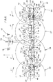
- La figure 1 représente une vue arrière d'une machine selon l'invention dans une première position de travail.
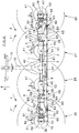
- La figure 2 représente une vue de dessus de cette machine.
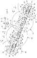
- La figure 3 représente une vue de dessus de la machine dans une deuxième position de travail.
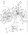
- La figure 4 représente une vue arrière de la machine en position de transport ou de dépose.
- La figure 5 représente une vue de côté de la machine selon la figure 4.
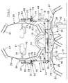
- La figure 6 représente une vue de dessus d'une machine selon un autre exemple de réalisation.
- Figure 1 shows a rear view of a machine according to the invention in a first working position.
- Figure 2 shows a top view of this machine.
- Figure 3 shows a top view of the machine in a second working position.
- Figure 4 shows a rear view of the machine in the transport or removal position.
- FIG. 5 represents a side view of the machine according to FIG. 4.
- FIG. 6 represents a top view of a machine according to another exemplary embodiment.
Tel que cela ressort des figures 1 à 5, la machine selon l'invention comporte un châssis support (1) de forme allongée. Ce châssis (1) se compose d'une partie centrale (2) et de deux parties latérales (3 et 4) qui sont articulées aux extrémitées de ladite partie centrale au moyen de pivots (5 et 6) sensiblement horizontaux. Des vérins hydrauliques (7 et 8) sont articulés sur la partie centrale (2) et chaque partie latérale (3 et 4).As shown in Figures 1 to 5, the machine according to the invention comprises a support frame (1) of elongated shape. This chassis (1) consists of a part central (2) and two lateral parts (3 and 4) which are articulated at the ends of said central part by means of pivots (5 and 6) substantially horizontal. Of hydraulic cylinders (7 and 8) are articulated on the central part (2) and each part lateral (3 and 4).
La partie centrale (2) est essentiellement formée de deux tubes (9 et 10) liés à un carter central (11) et d'un longeron (12) qui est sensiblement parallèle auxdits tubes. Une poutre de liaison (13) qui s'étend perpendiculairement au châssis (1) est reliée au longeron (12). Sur l'extrémité avant de cette poutre (13) est articulé, au moyen d'un axe (14) sensiblement vertical, un chevalet d'accouplement (15). Ce chevalet (15) est muni de trois points d'accouplement (16, 17 et 18) servant à fixer la machine au dispositif d'attelage trois points d'un tracteur non représenté. The central part (2) is essentially formed by two tubes (9 and 10) linked to a central casing (11) and a spar (12) which is substantially parallel to said tubes. A connecting beam (13) which extends perpendicular to the frame (1) is connected to the side member (12). On the front end of this beam (13) is articulated, at by means of a substantially vertical axis (14), a coupling bridge (15). This easel (15) is provided with three coupling points (16, 17 and 18) used to fix the machine to the three-point hitch of a tractor not shown.
Chaque partie latérale (3, 4) du châssis (1) se compose de deux segments (19 et 20, 21 et 22) de tubes. Les segments extérieurs (20, 22) sont montés sur les extrémités des segments intérieurs (19, 21) de manière à pouvoir tourner autour de leurs axes longitudinaux géométriques (23, 24). Lesdits segments intérieurs (19, 21) comportent des verrous (25, 26) permettant de bloquer les segments extérieurs (20, 22) dans au moins deux positions différentes.Each side part (3, 4) of the chassis (1) consists of two segments (19 and 20, 21 and 22) of tubes. The outer segments (20, 22) are mounted on the ends of the inner segments (19, 21) so that they can rotate around their geometric longitudinal axes (23, 24). Said interior segments (19, 21) have latches (25, 26) for blocking the outer segments (20, 22) in at least two different positions.
Dans l'exemple représenté, la partie centrale (2) du châssis (1) porte deux rotors (27, 28) tandis que le segment extérieur (20, 22) de chaque partie latérale (3 , 4) porte un rotor (29, 30) à son extrémité la plus éloignée. Ces rotors (27 à 30) se situent directement sous des carters (31 à 34) de la partie centrale (2) et des parties latérales (3, 4) du châssis (1). Ils sont tous sensiblement identiques. Chacun est constitué par un moyeu (35) auquel sont fixés plusieurs bras (36) portant des fourches de travail (37) à leurs extrémités extérieures. Chaque moyeu (35) est monté de manière à pouvoir tourner sur un axe support (38) qui est sensiblement vertical ou incliné dans la direction d'avancement (A). Chacun de ces axes (38) porte à son extrémité inférieure un bras (39) avec une colonne (40) munie d'une roue d'appui (41) qui roule sur le sol durant le travail.In the example shown, the central part (2) of the chassis (1) carries two rotors (27, 28) while the outer segment (20, 22) of each side part (3, 4) carries a rotor (29, 30) at its most distant end. These rotors (27 to 30) are located directly under casings (31 to 34) of the central part (2) and side parts (3, 4) of the chassis (1). They are all substantially identical. Each consists of a hub (35) to which are fixed several arms (36) carrying working forks (37) at their outer ends. Each hub (35) is mounted so that it can rotate on a support axis (38) which is substantially vertical or inclined in the direction of travel (A). Each of these axes (38) carries at its lower end an arm (39) with a column (40) provided with a support wheel (41) which rolls on the ground during work.
Lesdits rotors (27 à 30) peuvent être entraínés en rotation autour de leurs axes supports (38) à partir de l'arbre de prise de force du tracteur. A cet effet, chaque moyeu (35) comporte une couronne dentée avec laquelle engrène un pignon d'entraínement situé dans le carter (31 à 34) correspondant. Ces pignons d'entraínement sont montés sur des arbres de transmissions qui sont logés dans la partie centrale (2) et les parties latérales (3, 4) du châssis (1). Ces arbres sont reliés entre eux au moyen d'accouplements du type à doigts ou à cardans situés au niveau des pivots (5 et 6). L'arbre de transmission situé dans la partie centrale (2) passe dans le carter (11). Dans ce carter (11) il porte un pignon qui engrène avec un autre pignon solidaire d'un arbre (42) qui s'étend en direction du tracteur et qui peut être relié à l'arbre de prise de force de celui-ci au moyen d'un arbre de transmission intermédiaire.Said rotors (27 to 30) can be rotated around their support pins (38) from the tractor PTO shaft. To this end, each hub (35) has a ring gear with which meshes a drive gear located in the housing (31 to 34) corresponding. These gables are mounted on drive shafts which are housed in the central part (2) and the lateral parts (3, 4) of the chassis (1). These trees are interconnected by means of finger or cardan type couplings located at the level of pivots (5 and 6). The transmission shaft located in the central part (2) goes into the housing (11). In this casing (11) it carries a pinion which meshes with another pinion secured to a shaft (42) which extends towards the tractor and which can be connected to the PTO shaft thereof by means of a drive shaft intermediate.
Les axes supports (38) des rotors (27 à 30) sont montés pivotants dans des paliers de guidage prévus dans les carters (31 à 34) du châssis (1). Lesdits axes (38) traversent les parois supérieures des carters (31 à 34). Ils portent à leurs extrémités situées au-dessus de ces carters (31 à 34) des leviers de réglage (43 à 46) sensiblement horizontaux . Ces leviers (43 à 46) pourraient également sortir latéralement des carters (31 à 34). Ils sont tous reliés à des tiges de commande (47, 48, 49) situées derrière le châssis (1) au moyen d'axes d'articulation (50 à 53). Une première tige (47) est parallèle à la partie centrale (2) du châssis (1). Elle peut être déplacée longitudinalement au moyen d'un vérin hydraulique (54) qui est fixé sur ladite tige (47) et sur la partie centrale (2). Les tiges de commande (48 et 49) des axes supports (38) des rotors (29 et 30) des deux parties latérales (3 et 4) sont articulées aux extrémités de la première tige (47) au moyen d'axes (55 et 56) qui sont parallèles aux pivots (5 et 6) du châssis (1). Chacune de ces tiges de commande (48 et 49) est réalisée en un premier tronçon (57, 58) et un second tronçon (59, 60) qui sont munis de moyens (61, 62) d'accouplement et de désaccouplement.The support pins (38) of the rotors (27 to 30) are pivotally mounted in guide bearings provided in the casings (31 to 34) of the chassis (1). Said axes (38) pass through the upper walls of the casings (31 to 34). They carry to their ends situated above these casings (31 to 34) of the adjustment levers (43 to 46) substantially horizontal. These levers (43 to 46) could also come out laterally casings (31 to 34). They are all connected to control rods (47, 48, 49) located behind the chassis (1) by means of articulation pins (50 to 53). A first rod (47) is parallel to the central part (2) of the chassis (1). She may be moved longitudinally by means of a hydraulic cylinder (54) which is fixed on said rod (47) and on the central part (2). The control rods (48 and 49) of the support axes (38) of the rotors (29 and 30) of the two lateral parts (3 and 4) are articulated at the ends of the first rod (47) by means of pins (55 and 56) which are parallel to the pivots (5 and 6) of the chassis (1). Each of these control rods (48 and 49) is made in a first section (57, 58) and a second section (59, 60) which are provided with means (61, 62) for coupling and uncoupling.
Chacun des premiers tronçons (57, 58) est atticulé sur la première tige de commande (47) par l'axe (55, 56) et sur un levier de guidage (63, 64) au moyen d'un axe (65, 66) sensiblement vertical. Ce levier de guidage (63, 64) est lui-même articulé sur le segment intérieur (19, 21) de la partie latérale (3, 4) correspondante au moyen d'un axe (67, 68) sensiblement vertical. Chaque second tronçon (59, 60) est articulé, d'une part, sur le levier de réglage (43, 46) de l'axe support (38) du rotor (29, 30) de la partie latérale (3, 4) correspondante au moyen de l'axe (50, 53) sensiblement vertical et d'autre part, sur un levier de guidage (69, 70) également au moyen d'un axe (71, 72) sensiblement vertical. Ce levier de guidage (69, 70) est lui même articulé au moyen d'un axe (73, 74) sensiblement vertical sur le segment extérieur (20, 22) de la partie latérale (3, 4) correspondante du châssis (1).Each of the first sections (57, 58) is attached to the first rod of control (47) by the axis (55, 56) and on a guide lever (63, 64) by means a substantially vertical axis (65, 66). This guide lever (63, 64) is itself articulated on the inner segment (19, 21) of the corresponding lateral part (3, 4) by means of a substantially vertical axis (67, 68). Each second section (59, 60) is articulated, on the one hand, on the adjustment lever (43, 46) of the support axis (38) of the rotor (29, 30) of the corresponding side part (3, 4) by means of the axis (50, 53) substantially vertical and on the other hand, on a guide lever (69, 70) also by means of a substantially vertical axis (71, 72). This guide lever (69, 70) is itself articulated by means of an axis (73, 74) substantially vertical on the outer segment (20, 22) of the corresponding lateral part (3, 4) of the chassis (1).
Il ressort des figures annexées que les moyens (61, 62) d'accouplement et de désaccouplement des tronçons (57 à 60) des tiges de commande (48 et 49) des axes supports (38) des rotors (29 et 30) des deux parties latérales (3 et 4) sont constitués par des axes d'accrochage (75) et des encoches (76). Chacun desdits axes d'accrochage (75) est fixé à l'extrémité dirigé vers l'extérieur du premier tronçon (57, 58) de chaque tiges de commande (48, 49). Ces axes (75) sont dirigés dans la direction d'avancement (A). Chacune des encoches (76) se situe dans une plaque (77) qui est solidaire du second tronçon (59, 60) de chaque tige de commande (48, 49). Ces encoches (76) sont en forme de V. Au moins un des bords de ces encoches (76) est prolongé et constitue une rampe de guidage (78).It appears from the appended figures that the means (61, 62) of coupling and for uncoupling the sections (57 to 60) of the control rods (48 and 49) of the support axes (38) of the rotors (29 and 30) of the two lateral parts (3 and 4) are constituted by attachment pins (75) and notches (76). Each of said attachment pins (75) is fixed to the outwardly directed end of the first section (57, 58) of each control rod (48, 49). These axes (75) are directed in the direction of advancement (A). Each of the notches (76) is located in a plate (77) which is integral with the second section (59, 60) of each control rod (48, 49). These notches (76) are V-shaped. At least one of the edges of these notches (76) is extended and constitutes a guide ramp (78).
La machine selon l'exemple de réalisation de la figure 6 a une configuration générale analogue à celle des figures 1 à 5 et ne sera donc plus décrite en détails. Sur cette machine le levier de réglage (43, 46) de l'axe support (38) du rotor (29, 30) de chaque partie latérale (3, 4) du châssis (1) et le levier de guidage (63, 64) du premier tronçon (57, 58) de chaque tige de commande (48, 49) sont reliés entre eux par des câbles (79 et 80). Ceux-ci sont disposés dans des gaines de guidage (81 et 82) qui sont fixées à chacune de leurs extrémités sur des plaques (83 et 84) dont l'une est solidaire du segment intérieur (19, 21) et l'autre du segment extérieur (20, 22) de la partie latérale (3 ou 4) correspondante. Sur chaque partie latérale (3, 4), un (80) des câbles (79 et 80) est fixé au levier de réglage (43, 46) et au levier de guidage (63, 70) dans leurs parties qui se situent entre leurs axes (38 et 67, 68) respectifs et leurs axes d'articulation (50, 53 et 65, 66) sur les tronçons (57 à 60). Les points de fixation dudit câble (80) sur les deux leviers (43, 46 et 63, 64) se situent derrière lesdits axes (38 et 67, 68) (vu dans la direction d'avancement A) et sensiblement à la même distance de ceux-ci. L'autre câble (79) est fixé sur des prolongements (85, 86 et 87, 88) des leviers (43, 46 et 63, 64). Ces prolongements s'étendent vers l'avant (vu dans la direction d'avancement A), au-delà des axes (38 et 67, 68). Les points de fixation de ce câble (79) sur lesdits prolongements (85 à 88) se situent sensiblement à la même distance des axes (38 et 67, 68) respectifs. Par ailleurs, la longueur des câbles (79 et 80) est telle qu'ils puissent s'étendre autour de la partie latérale (3, 4) correspondante du châssis (1) dans la position de travail (voir la figure 6).The machine according to the embodiment of Figure 6 has a configuration general similar to that of Figures 1 to 5 and will therefore no longer be described in detail. On this machine the adjusting lever (43, 46) of the support axis (38) of the rotor (29, 30) of each side part (3, 4) of the frame (1) and the guide lever (63, 64) of the first section (57, 58) of each control rod (48, 49) are connected between them by cables (79 and 80). These are arranged in guide sleeves (81 and 82) which are fixed at each of their ends on plates (83 and 84) one of which is integral with the interior segment (19, 21) and the other with the exterior segment (20, 22) of the corresponding side part (3 or 4). On each side part (3, 4), one (80) of the cables (79 and 80) is fixed to the adjustment lever (43, 46) and to the lever guide (63, 70) in their parts which lie between their axes (38 and 67, 68) respective and their axes of articulation (50, 53 and 65, 66) on the sections (57 to 60). The fixing points of said cable (80) on the two levers (43, 46 and 63, 64) are located behind said axes (38 and 67, 68) (seen in the direction of advance A) and substantially the same distance from them. The other cable (79) is fixed on extensions (85, 86 and 87, 88) of the levers (43, 46 and 63, 64). These extensions extend forward (seen in direction of travel A), beyond axes (38 and 67, 68). The fixing points of this cable (79) on said extensions (85 to 88) are located substantially at the same distance from the axes (38 and 67, 68) respectively. Furthermore, the length of the cables (79 and 80) is such that they can extend around the corresponding side part (3, 4) of the chassis (1) in the working position (see Figure 6).
La machine décrite en liaison avec les figures 1 à 5 est destinée au fanage. Durant le travail elle est accouplée à un tracteur qui permet de la déplacer dans la direction (A). Les rotors (27 à 30) sont entraínés en rotation, autour de leurs axes supports (38) respectifs, de telle sorte qu'ils tournent deux à deux en convergence à l'avant (flèches F et F'). Lors de cette rotation, leurs fourches (37) ramassent sur la partie avant de leur trajectoire les végétaux qui se trouvent sur le sol, les entraínent vers l'arrière et les étalent à nouveau tout en provoquant leur retournement. Les différents rotors (27 à 30) peuvent suivre les dénivellations du sol en pivotant avec les parties correspondantes (2, 3 et 4) du châssis (1) autour des pivots (5 et 6). L'ensemble du châssis (1) peut aussi pivoter autour de l'axe d'articulation (14) avec le chevalet d'accouplement (15) afin que les rotors (27 à 30) puissent bien suivre le tracteur. Par ailleurs les deux tronçons (57, 58 et 59, 60) des tiges de commande (48 et 49) des axes supports (38) des rotors (29 et 30) des parties latérales (3 et 4) sont accouplés entre eux. Leurs axes d'accrochage (75) se situent alors dans les encoches (76).The machine described in connection with Figures 1 to 5 is intended for tedding. During work it is coupled to a tractor which allows it to be moved in the direction to). The rotors (27 to 30) are rotated around their axes respective supports (38), so that they rotate in pairs in convergence at the front (arrows F and F '). During this rotation, their forks (37) pick up on the front part of their trajectory the plants which are on the ground, entrain them backwards and spread them out again while causing them to overturn. The different rotors (27 to 30) can follow the unevenness of the ground by pivoting with the corresponding parts (2, 3 and 4) of the chassis (1) around the pivots (5 and 6). The entire chassis (1) can also pivot around the hinge pin (14) with the coupling bridge (15) so that the rotors (27 to 30) can properly follow the tractor. Furthermore, the two sections (57, 58 and 59, 60) of the rods control (48 and 49) of the support pins (38) of the rotors (29 and 30) of the lateral parts (3 and 4) are coupled together. Their attachment axes (75) are located then in the notches (76).
Dans la première position de travail qui est représentée sur les figures 1 et 2, le châssis (1) et les rotors (27 à 30) se situent sur une ligne sensiblement perpendiculaire au sens d'avancement (A). Lesdits rotors (27 à 30) projettent alors les végétaux dans la direction opposée au sens d'avancement (A), de telle sorte qu'ils retombent pratiquement sur la même bande de terrain. Les roues d'appui (41) sont bloquées dans une direction dans laquelle elles sont sensiblement perpendiculaires au châssis (1). Ce blocage est assuré au moyen du vérin hydraulique (54) qui bloque les tiges de commande (47, 48 et 49). Celles-ci bloquent à leur tour par l'intermédiaire des leviers (43 à 46) les axes supports (38) qui portent les roues (41). Il peut éventuellement être prévu un dispositif de bloquage mécanique supplémentaire disposé entre le châssis (1) et les tiges de commande (47 à 49) afin de mieux définir les différentes positions de ces dernières. Ce dispositif serait avantageusement commandé depuis le tracteur. In the first working position which is shown in Figures 1 and 2, the frame (1) and the rotors (27 to 30) are located on a substantially perpendicular line in the direction of travel (A). Said rotors (27 to 30) then project the plants in the opposite direction to the direction of travel (A), so that they practically fall on the same strip of land. Support wheels (41) are blocked in a direction in which they are substantially perpendicular to the chassis (1). This blocking is ensured by means of the hydraulic cylinder (54) which blocks the control rods (47, 48 and 49). These in turn block by the levers (43 to 46) the support pins (38) which carry the wheels (41). An additional mechanical blocking device can optionally be provided disposed between the chassis (1) and the control rods (47 to 49) in order to better define the different positions of these. This device would advantageously controlled from the tractor.
La machine peut être transposée dans la deuxième position de travail représentée sur la figure 3 en actionnant le vérin hydraulique (54) de telle sorte qu'il se raccourcisse. Il déplace alors les tiges de commande (47, 48 et 49) vers le côté droit de la machine. Celles-ci entraínent tous les leviers de réglage (43 à 46) qui font tourner les axes supports (38) sur eux-mêmes. Ces axes (38) orientent alors les roues d'appui (41) vers le côté gauche du châssis (1) jusqu'à ce qu'elles forment des angles d'environ 25° par rapport à leurs positions initiales. Toutefois, étant donné que ces roues d'appui (41) se placent automatiquement dans la direction d'avancement (A) lorsque la machine est déplacée, l'ensemble du châssis (1) tourne autour de l'axe d'articulation (14) du chevalet d'accouplement (15) et prend une position oblique par rapport à la direction d'avancement (A). Les rotors (27 à 30) se situent alors également sur une ligne oblique et ils déplacent les végétaux en biais par rapport à la direction d'avancement (A).The machine can be moved to the second working position shown in Figure 3 by operating the hydraulic cylinder (54) so that it shortens. It then moves the control rods (47, 48 and 49) to the side machine right. These drive all the adjustment levers (43 to 46) which rotate the support pins (38) on themselves. These axes (38) then orient the support wheels (41) towards the left side of the chassis (1) until they form angles of about 25 ° from their initial positions. However, being given that these support wheels (41) are automatically positioned in the direction advancement (A) when the machine is moved, the whole chassis (1) rotates around the hinge pin (14) of the coupling bridge (15) and takes an oblique position relative to the direction of advance (A). The rotors (27 to 30) are then also located on an oblique line and they move the plants in bias relative to the direction of advancement (A).
Pour revenir dans la première position de travail, il suffit de commander le vérin hydraulique (54) de sorte qu'il s'allonge et ramène les tiges de commande (47, 48 et 49), les leviers (43 à 46), les axes supports (38) et les roues d'appui (41) dans leurs positions initiales.To return to the first working position, simply order the hydraulic cylinder (54) so that it lengthens and brings back the control rods (47, 48 and 49), the levers (43 to 46), the support pins (38) and the support wheels (41) in their original positions.
La machine peut également être transposée dans une troisième position de travail qui n'est pas représentée. Dans cette position le châssis (1) est incliné dans une position inverse à celle de la figure 3. Elle est obtenue en allongeant le vérin hydraulique (54) lorsqu'il est dans la première position de travail.The machine can also be transposed to a third position work which is not represented. In this position the frame (1) is inclined in a position opposite to that of FIG. 3. It is obtained by lengthening the jack hydraulic (54) when in the first working position.
Pour mettre la machine en position de transport les parties latérales (3 et 4) du châssis (1) sont relevées dans une position sensiblement verticale au moyen des vérins hydrauliques (7 et 8). Ensuite, les segments extérieurs (20 et 22) de ces parties latérales (3 et 4) sont débloquées et tournées d'environ 180° autour de leurs axes longitudinaux géométriques (23 et 24) pour amener les rotors (29 et 30) correspondants au dessus de la partie centrale (2) avec les fourches (37) orientées vers le milieu de la machine. Au cours de cette rotation les deuxièmes tronçons (59 et 60) des tiges de commande (48 et 49) tournent avec lesdits segments extérieurs (20 et 22). Les plaques (77) avec les encoches (76) se détachent alors automatiquement des axes d'accrochage (75) des premiers tronçons (57 et 58) (voir figures 4 et 5).To put the machine in the transport position the side parts (3 and 4) of the chassis (1) are raised in a substantially vertical position by means of the hydraulic cylinders (7 and 8). Then, the outer segments (20 and 22) of these side parts (3 and 4) are unlocked and turned about 180 ° around their geometric longitudinal axes (23 and 24) to bring the corresponding rotors (29 and 30) above the central part (2) with the forks (37) oriented towards the middle of the machine. During this rotation the second sections (59 and 60) control rods (48 and 49) rotate with said outer segments (20 and 22). The plates (77) with the notches (76) then detach automatically attachment axes (75) of the first sections (57 and 58) (see figures 4 and 5).
Inversement, pour remettre la machine en position de travail il faut tourner les segments extérieurs (20 et 22) de manière à ramener leurs rotors (29 et 30) vers l'extérieur. Les plaques (77) des deuxièmes tronçons (59 et 60) reviennent alors vers les axes d'accrochage (75). Lorsque les rampes (78) rencontrent ces axes (75), elles ramènent les plaques (77) et les deuxièmes tronçons (59 et 60) dans la position dans laquelle les encoches (76) peuvent s'engager automatiquement sur lesdits axes (75). Dès lors la liaison entre les deux tronçons (57, 58 et 59, 60) de chaque tiges de commande (48, 49) est rétablie. Il est alors à nouveau possible de régler la position de travail tel que cela a été décrit précédemment. Enfin, les parties latérales (3 et 4) du châssis (1) peuvent être abaissées au moyen des vérins hydrauliques (7 et 8).Conversely, to return the machine to the working position it is necessary to turn the outer segments (20 and 22) so as to bring their rotors (29 and 30) towards outside. The plates (77) of the second sections (59 and 60) then return towards the attachment axes (75). When the ramps (78) meet these axes (75), they return the plates (77) and the second sections (59 and 60) to the position in which the notches (76) can automatically engage on said axes (75). Consequently, the connection between the two sections (57, 58 and 59, 60) of each control rods (48, 49) is restored. It is then again possible to adjust the working position as described above. Finally, the side parts (3 and 4) of the chassis (1) can be lowered by means of the hydraulic cylinders (7 and 8).
Il est possible de réaliser la machine selon l'invention de telle sorte que les déplacements en hauteur des parties latérales (3 et 4) et les pivotements de leurs segments extérieurs (20 et 22) soient combinés.It is possible to make the machine according to the invention so that the displacements in height of the lateral parts (3 and 4) and the pivoting of their outer segments (20 and 22) are combined.
La machine selon l'exemple de réalisation de la figure 6 peut être transposée dans les mêmes positions de travail que celles décrites précédemment. Pour la transposer de la position de travail dans la position de transport et inversement, les parties latérales (3 et 4) du châssis (1) sont également déplacées en hauteur et leurs segments extérieurs (20 et 22) sont pivotés d'environ 180° avec les deuxièmes tronçons (59 et 60) par rapport aux segments intérieurs (19 et 21) et aux premiers tronçons (57 et 58). Toutefois, lors du pivotement des deuxièmes tronçons (59 et 60) des tiges de commande (48 et 49), les câbles (79 et 80) maintiennent constamment lesdits deuxièmes tronçons (59 et 60) dans les positions qu'ils occupaient au moment de la séparation d'avec les premiers tronçons (57 et 58). De ce fait, les encoches (76) de leurs plaques (77) se situent immédiatement au niveau des axes d'accrochage (75) lors du retour vers la position de travail, ce qui facilite le rétablissement de la liaison entre les deux tronçons (57, 58 et 59, 60). On comprendra que les extrémités des câbles (79 et 80) qui sont reliées aux segments extérieurs (20 et 22) des parties latérales (3 et 4) pivotent avec lesdits segments (20 et 22) lors de leurs déplacements.The machine according to the embodiment of Figure 6 can be transposed in the same working positions as those described above. For the transpose from the working position to the transport position and vice versa, the lateral parts (3 and 4) of the chassis (1) are also displaced in height and their outer segments (20 and 22) are rotated approximately 180 ° with the second sections (59 and 60) relative to the interior segments (19 and 21) and to the first sections (57 and 58). However, during the pivoting of the second sections (59 and 60) control rods (48 and 49), cables (79 and 80) maintain constantly said second sections (59 and 60) in the positions they occupied at the time of separation from the first sections (57 and 58). Thereby, the notches (76) of their plates (77) are located immediately at the level of the attachment pins (75) when returning to the working position, which facilitates the reestablishment of the link between the two sections (57, 58 and 59, 60). We will understand that the ends of the cables (79 and 80) which are connected to the outer segments (20 and 22) lateral parts (3 and 4) pivot with said segments (20 and 22) while traveling.
Il est bien évident que l'invention n'est pas limitée aux modes de réalisation décrits et représentés sur les dessins annexés. Des modifications sont possibles, notamment en ce qui concerne la constitution des divers éléments ou par substitution d'équivalents techniques, sans sortir pour autant du domaine de protection défini par les revendications.It is obvious that the invention is not limited to the embodiments described and shown in the accompanying drawings. Modifications are possible, especially regarding the constitution of the various elements or by substitution technical equivalents, without going beyond the scope of protection defined by the claims.
Claims (10)
- Haymaking machine, especially a tedder for plants, which can be coupled to a tractor and which comprises a support chassis (1) of elongate shape, made up of a central part (2) and two lateral parts (3 and 4) which are articulated to the ends of the said central part (2) by means of pivots (5 and 6) about which they can be moved heightwise through an angle of about 90° for transport, which chassis (1) bears several rotors (27 to 30) situated below the central part (2) and the lateral parts (3 and 4) and which can be rotated during work about support axes (38) which at their lower ends bear wheels (41) for resting on the ground, each of the said lateral parts (3 and 4) being made of an inner segment (19, 21) and an outer segment (20, 22) which bears the corresponding rotor (29, 30) and which can rotate about its longitudinal axis (23, 24) with respect to the inner segment (19, 21) in order to bring the said rotor (29, 30) substantially above the central part (2) with the working forks (37) directed towards the middle of the machine when the said lateral parts (3 and 4) are moved heightwise for transport, characterized in that the support axes (38) of the rotors (27 to 30) are mounted so that they can pivot in bearings of the chassis (1) of the machine, in that the said support axes (38) comprise adjusting levers (43 to 46) which are connected together by operating rods (47, 48 and 49) and in that the operating rods (48 and 49) of the adjusting levers (43 and 46) of the support axes (38) of the two rotors (29 and 30) of the lateral parts (3 and 4) are made of a first portion (57, 58) and a second portion (59, 60) which are equipped with means (61 and 62) of coupling and uncoupling.
- Machine according to Claim 1, characterized in that the first portion (57, 58) of each operating rod (48, 49) is articulated to the operating rod (47) which connects the levers (44 and 45) of the support axes (38) of the rotors (27 and 28) of the central part (2) and to a guide lever (63, 64) which is articulated to the inner segment (19, 21) of the corresponding lateral part (3, 4) of the chassis (1).
- Machine according to Claim 1, characterized in that the second portion (59, 60) of each operating rod (48, 49) is articulated to the adjusting lever (43, 46) of the support axis (38) of the rotor (29, 30) of the corresponding lateral part (3, 4) and to a guide lever (69, 70) which is approximately parallel to the said adjusting lever (43, 46) and which is articulated to the outer segment (20, 22) of the lateral part (3, 4) of the chassis (1).
- Machine according to Claim 2, characterized in that the first portion (57, 58) of each operating rod (48, 49) comprises a connecting pin (75).
- Machine according to Claim 4, characterized in that the connecting pin (75) is directed in the direction of advance (A).
- Machine according to Claims 3 and 4, characterized in that the second portion (59, 60) of each operating rod (48, 49) comprises a plate (77) that has a cut-out (76) in which the connecting pin (75) of the corresponding first portion (57, 58) can be housed.
- Machine according to Claim 6, characterized in that the cut-out (76) is V-shaped.
- Machine according to Claim 6 or 7, characterized in that at least one of the edges of the cut-out (76) is extended and constitutes a guide ramp (78).
- Machine according to any one of the preceding claims, characterized in that the adjusting lever (43, 46) of the support axis (38) of the rotor (29, 30) of each lateral part (3, 4) of the chassis (1) and the guide lever (63, 64) of the first portion (57, 58) of each operating rod (48, 49) are connected to each other by cables (79 and 80) placed in guide sheaths (81 and 82) each of which sheaths is fixed at each of its ends to plates (83 and 84), one (83) of which is secured to the inner segment (19, 21) and the other (84) of which is secured to the outer segment (20, 22) of the corresponding lateral part (3, 4).
- Machine according to Claim 9, characterized in that the adjusting lever (43, 46) and the guide lever (63, 64) comprise extensions (85 to 88) which extend beyond their respective axes (38 and 67, 68), one (79) of the cables (79, 80) being connected to the said extensions (85 to 88) which are located in front of the said axes (38 and 67, 68), and the other cable (80) being connected to the parts of the levers (43, 46, 63, 64) which lie behind the said axes (38 and 67, 68) (when viewed in the direction of advance A).
Applications Claiming Priority (2)
| Application Number | Priority Date | Filing Date | Title |
|---|---|---|---|
| FR9503453 | 1995-03-20 | ||
| FR9503453A FR2731873B1 (en) | 1995-03-20 | 1995-03-20 | HAYMAKING MACHINE, ESPECIALLY A PLANT TEDDER, TRANSPOSABLE IN SEVERAL POSITIONS |
Publications (2)
| Publication Number | Publication Date |
|---|---|
| EP0733302A1 EP0733302A1 (en) | 1996-09-25 |
| EP0733302B1 true EP0733302B1 (en) | 1999-09-22 |
Family
ID=9477371
Family Applications (1)
| Application Number | Title | Priority Date | Filing Date |
|---|---|---|---|
| EP96440024A Expired - Lifetime EP0733302B1 (en) | 1995-03-20 | 1996-03-08 | Haymaking machine |
Country Status (4)
| Country | Link |
|---|---|
| EP (1) | EP0733302B1 (en) |
| AT (1) | ATE184744T1 (en) |
| DE (1) | DE69604317T2 (en) |
| FR (1) | FR2731873B1 (en) |
Families Citing this family (3)
| Publication number | Priority date | Publication date | Assignee | Title |
|---|---|---|---|---|
| NL1006999C2 (en) * | 1997-09-11 | 1999-03-12 | Maasland Nv | Folding agricultural machine as well as a method for folding up that agricultural machine from the working position to the transport position. |
| FR2787286B1 (en) * | 1998-12-18 | 2001-02-16 | Kuhn Sa | FENAISON MACHINE WITH COMBINED HYDRAULIC CONTROL FOR LIFT OF SIDE SECTION OR WHEEL ORIENTATION |
| CN103828547A (en) * | 2012-11-26 | 2014-06-04 | 烟台萨姆肯汽车配件制造有限公司 | Tedder |
Family Cites Families (6)
| Publication number | Priority date | Publication date | Assignee | Title |
|---|---|---|---|---|
| DE2419749A1 (en) * | 1974-04-24 | 1975-11-06 | Fella Werke Gmbh | Hay-making machine - horizontal rigid cross-beam supported on two land-wheels and pivot-mounted rotating finger-wheels on pivot axles |
| FR2582186B1 (en) * | 1985-05-21 | 1989-05-05 | Kuhn Sa | IMPROVEMENT IN FENAISON MACHINES WITH MULTIPLE RAKING WHEELS |
| DE8807510U1 (en) * | 1988-06-09 | 1989-07-06 | Alois Poettinger Landmaschinen-Gesellschaft Mbh, 8900 Augsburg, De | |
| DE4219484B4 (en) * | 1992-06-13 | 2005-03-17 | Alois Pöttinger Landmaschinen Gmbh | Hay-making machine |
| DE9210001U1 (en) * | 1992-07-24 | 1992-09-24 | Greenland Gmbh & Co Kg, 7702 Gottmadingen, De | |
| FR2712767B1 (en) * | 1993-11-23 | 1996-02-09 | Kuhn Sa | Haymaking machine that can be transferred to several working positions. |
-
1995
- 1995-03-20 FR FR9503453A patent/FR2731873B1/en not_active Expired - Fee Related
-
1996
- 1996-03-08 AT AT96440024T patent/ATE184744T1/en active
- 1996-03-08 EP EP96440024A patent/EP0733302B1/en not_active Expired - Lifetime
- 1996-03-08 DE DE69604317T patent/DE69604317T2/en not_active Expired - Lifetime
Also Published As
| Publication number | Publication date |
|---|---|
| ATE184744T1 (en) | 1999-10-15 |
| DE69604317T2 (en) | 2000-04-20 |
| FR2731873A1 (en) | 1996-09-27 |
| FR2731873B1 (en) | 1997-06-13 |
| EP0733302A1 (en) | 1996-09-25 |
| DE69604317D1 (en) | 1999-10-28 |
Similar Documents
| Publication | Publication Date | Title |
|---|---|---|
| FR2654893A1 (en) | AGRICULTURAL MACHINE WITH DEVICE FOR SUSPENSION OF THE WORKING GROUP OF PERFECTED WORK. | |
| EP0385899B1 (en) | Hay-making machine having a plurality of rotors | |
| FR2648310A1 (en) | AGRICULTURAL MACHINE FOR RAKING, COMPRISING REPLIABLE TOOL HOLDERS | |
| EP1290936A1 (en) | Haymaking machine | |
| FR2746576A1 (en) | AGRICULTURAL MACHINE OF THE GENUS FANEUSE WITH MULTIPLE ROTARY RAKES, CONVERTIBLE FROM A WORKING POSITION DEPLOYED TO A POSITION OF TRANSPORTED TRANSPORT | |
| EP1142468B1 (en) | Haymaking machine | |
| EP0310532B2 (en) | Hay-making machine having an improved protective device | |
| EP0733302B1 (en) | Haymaking machine | |
| FR2664127A1 (en) | AGRICULTURAL MACHINE, ESPECIALLY AN ANDAINEUSE OF PLANTS, WITH ADJUSTABLE WORKING WIDTH. | |
| EP0797913B1 (en) | Haymaking machine | |
| EP0554200B1 (en) | Haymaking machine comprising a frame with controlled support wheels | |
| EP0536071B1 (en) | Haymaking machine, especially a crop tedder, with at least two work positions | |
| EP0426588A1 (en) | Improvement for agricultural machines especially for haymaking machines | |
| EP0857413A1 (en) | Haymaking machine | |
| EP0654209B1 (en) | Haymaking machine | |
| EP0593378B1 (en) | Haymaking machine for the windrowing of forage | |
| EP0772970B1 (en) | Haymaking machine, especially a tedder | |
| EP1013161B1 (en) | Haymaking machine | |
| EP0779022A1 (en) | Haymaking machine | |
| EP0486415B1 (en) | Mower with an independent frame comprising a suspension device and a lightening device | |
| EP0442833B1 (en) | Haymaking machine with an improved safety device | |
| EP0811314B1 (en) | Agricultural machine | |
| EP0532443A1 (en) | Haymaking machine with adjustable wheels | |
| FR2699044A1 (en) | Haymaking machine with displaceable wheels - comprises wheel arm carriers connected to pivoting axle with hydraulic actuator operated rack and pinion | |
| EP0617883A1 (en) | Haymaking machine, especially a tedder |
Legal Events
| Date | Code | Title | Description |
|---|---|---|---|
| PUAI | Public reference made under article 153(3) epc to a published international application that has entered the european phase |
Free format text: ORIGINAL CODE: 0009012 |
|
| AK | Designated contracting states |
Kind code of ref document: A1 Designated state(s): AT DE FR IT NL |
|
| 17P | Request for examination filed |
Effective date: 19970224 |
|
| GRAG | Despatch of communication of intention to grant |
Free format text: ORIGINAL CODE: EPIDOS AGRA |
|
| GRAG | Despatch of communication of intention to grant |
Free format text: ORIGINAL CODE: EPIDOS AGRA |
|
| GRAH | Despatch of communication of intention to grant a patent |
Free format text: ORIGINAL CODE: EPIDOS IGRA |
|
| 17Q | First examination report despatched |
Effective date: 19990305 |
|
| GRAH | Despatch of communication of intention to grant a patent |
Free format text: ORIGINAL CODE: EPIDOS IGRA |
|
| GRAA | (expected) grant |
Free format text: ORIGINAL CODE: 0009210 |
|
| AK | Designated contracting states |
Kind code of ref document: B1 Designated state(s): AT DE FR IT NL |
|
| REF | Corresponds to: |
Ref document number: 184744 Country of ref document: AT Date of ref document: 19991015 Kind code of ref document: T |
|
| ITF | It: translation for a ep patent filed |
Owner name: BARZANO' E ZANARDO MILANO S.P.A. |
|
| REF | Corresponds to: |
Ref document number: 69604317 Country of ref document: DE Date of ref document: 19991028 |
|
| PLBE | No opposition filed within time limit |
Free format text: ORIGINAL CODE: 0009261 |
|
| STAA | Information on the status of an ep patent application or granted ep patent |
Free format text: STATUS: NO OPPOSITION FILED WITHIN TIME LIMIT |
|
| 26N | No opposition filed | ||
| PGFP | Annual fee paid to national office [announced via postgrant information from national office to epo] |
Ref country code: NL Payment date: 20110225 Year of fee payment: 16 Ref country code: IT Payment date: 20110226 Year of fee payment: 16 Ref country code: AT Payment date: 20110221 Year of fee payment: 16 |
|
| PGFP | Annual fee paid to national office [announced via postgrant information from national office to epo] |
Ref country code: FR Payment date: 20110412 Year of fee payment: 16 Ref country code: DE Payment date: 20110308 Year of fee payment: 16 |
|
| REG | Reference to a national code |
Ref country code: NL Ref legal event code: V1 Effective date: 20121001 |
|
| REG | Reference to a national code |
Ref country code: AT Ref legal event code: MM01 Ref document number: 184744 Country of ref document: AT Kind code of ref document: T Effective date: 20120308 |
|
| REG | Reference to a national code |
Ref country code: FR Ref legal event code: ST Effective date: 20121130 |
|
| REG | Reference to a national code |
Ref country code: DE Ref legal event code: R119 Ref document number: 69604317 Country of ref document: DE Effective date: 20121002 |
|
| PG25 | Lapsed in a contracting state [announced via postgrant information from national office to epo] |
Ref country code: FR Free format text: LAPSE BECAUSE OF NON-PAYMENT OF DUE FEES Effective date: 20120402 Ref country code: AT Free format text: LAPSE BECAUSE OF NON-PAYMENT OF DUE FEES Effective date: 20120308 |
|
| PG25 | Lapsed in a contracting state [announced via postgrant information from national office to epo] |
Ref country code: IT Free format text: LAPSE BECAUSE OF NON-PAYMENT OF DUE FEES Effective date: 20120308 |
|
| PG25 | Lapsed in a contracting state [announced via postgrant information from national office to epo] |
Ref country code: NL Free format text: LAPSE BECAUSE OF NON-PAYMENT OF DUE FEES Effective date: 20121001 |
|
| PG25 | Lapsed in a contracting state [announced via postgrant information from national office to epo] |
Ref country code: DE Free format text: LAPSE BECAUSE OF NON-PAYMENT OF DUE FEES Effective date: 20121002 |