EP0733302B1 - Machine de fenaison - Google Patents
Machine de fenaison Download PDFInfo
- Publication number
- EP0733302B1 EP0733302B1 EP96440024A EP96440024A EP0733302B1 EP 0733302 B1 EP0733302 B1 EP 0733302B1 EP 96440024 A EP96440024 A EP 96440024A EP 96440024 A EP96440024 A EP 96440024A EP 0733302 B1 EP0733302 B1 EP 0733302B1
- Authority
- EP
- European Patent Office
- Prior art keywords
- chassis
- machine according
- axes
- support
- rotors
- Prior art date
- Legal status (The legal status is an assumption and is not a legal conclusion. Google has not performed a legal analysis and makes no representation as to the accuracy of the status listed.)
- Expired - Lifetime
Links
- 230000008878 coupling Effects 0.000 claims abstract description 10
- 238000010168 coupling process Methods 0.000 claims abstract description 10
- 238000005859 coupling reaction Methods 0.000 claims abstract description 10
- 230000000284 resting effect Effects 0.000 claims 1
- 239000004459 forage Substances 0.000 description 4
- 230000000903 blocking effect Effects 0.000 description 3
- 238000006073 displacement reaction Methods 0.000 description 2
- 241001465754 Metazoa Species 0.000 description 1
- 230000004888 barrier function Effects 0.000 description 1
- 230000005540 biological transmission Effects 0.000 description 1
- 230000013011 mating Effects 0.000 description 1
- 230000004048 modification Effects 0.000 description 1
- 238000012986 modification Methods 0.000 description 1
- 238000000926 separation method Methods 0.000 description 1
- 238000006467 substitution reaction Methods 0.000 description 1
Images

Classifications
-
- A—HUMAN NECESSITIES
- A01—AGRICULTURE; FORESTRY; ANIMAL HUSBANDRY; HUNTING; TRAPPING; FISHING
- A01D—HARVESTING; MOWING
- A01D78/00—Haymakers with tines moving with respect to the machine
- A01D78/08—Haymakers with tines moving with respect to the machine with tine-carrying rotary heads or wheels
- A01D78/10—Haymakers with tines moving with respect to the machine with tine-carrying rotary heads or wheels the tines rotating about a substantially vertical axis
- A01D78/1007—Arrangements to facilitate transportation specially adapted therefor
- A01D78/1014—Folding frames
-
- A—HUMAN NECESSITIES
- A01—AGRICULTURE; FORESTRY; ANIMAL HUSBANDRY; HUNTING; TRAPPING; FISHING
- A01D—HARVESTING; MOWING
- A01D78/00—Haymakers with tines moving with respect to the machine
- A01D78/08—Haymakers with tines moving with respect to the machine with tine-carrying rotary heads or wheels
- A01D78/10—Haymakers with tines moving with respect to the machine with tine-carrying rotary heads or wheels the tines rotating about a substantially vertical axis
- A01D78/1028—Pivotable rotor support arms
- A01D78/1035—Pivotable rotor support arms pivotable by orientation of the support wheels
Definitions
- the present invention relates to a haymaking machine, in particular a plant tedder, which can be coupled to a tractor and which has a support frame of elongated shape, consisting of a central part and two lateral parts which are articulated at the ends of said central part at by means of pivots around which they can be moved in height by a angle of approximately 90 ° for transport, which chassis carries several rotors located under the central part and the lateral parts and can be driven in rotation during work around support axes which carry at their lower ends ground support wheels, each of said lateral parts being made of an inner segment and an outer segment which carries the corresponding rotor and which can rotate around its longitudinal axis relative to the inner segment to bring said rotor substantially above the central part with the forks working towards the middle of the machine, when said lateral parts are moved in height for transport.
- a machine of this kind is known in European patent No. 0203 023.
- the working forks of the rotors which are raised during the transport, are not dangerous for people, animals or vehicles that can be found or passed nearby.
- this machine cannot only be used in one working position. In this position the chassis with rotors is substantially perpendicular to the direction of travel. The rotors then project the right forage backwards, so that it remains substantially on the same strip of land.
- a piece of land is bordered by a path, ditch or barrier, it is very important to be able to keep it away forage during tedding.
- the present invention aims to provide a haymaking machine with external rotors orientable towards the middle of the machine during transport and which can easily be transferred to another working position in which its rotors move the forage obliquely away from the edge of a field.
- an important characteristic of the invention consists in that the support axes of the rotors are pivotally mounted in bearings of the chassis of the machine, that said support pins have adjustment levers which are interconnected by means of control rods and that the control rods levers for adjusting the support axes of the two rotors of the lateral parts are made in a first section and a second section which are provided with means coupling and uncoupling.
- each side part is pivoted by an angle of about 180 ° in opposite directions.
- the two sections of the control rod then automatically couple so that you can adjust the position of the support pin and the caster wheel again corresponding rotor.
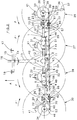
- the machine according to the invention comprises a support frame (1) of elongated shape.
- This chassis (1) consists of a part central (2) and two lateral parts (3 and 4) which are articulated at the ends of said central part by means of pivots (5 and 6) substantially horizontal.
- hydraulic cylinders (7 and 8) are articulated on the central part (2) and each part lateral (3 and 4).
- the central part (2) is essentially formed by two tubes (9 and 10) linked to a central casing (11) and a spar (12) which is substantially parallel to said tubes.
- a connecting beam (13) which extends perpendicular to the frame (1) is connected to the side member (12).
- On the front end of this beam (13) is articulated, at by means of a substantially vertical axis (14), a coupling bridge (15).
- This easel (15) is provided with three coupling points (16, 17 and 18) used to fix the machine to the three-point hitch of a tractor not shown.
- Each side part (3, 4) of the chassis (1) consists of two segments (19 and 20, 21 and 22) of tubes.
- the outer segments (20, 22) are mounted on the ends of the inner segments (19, 21) so that they can rotate around their geometric longitudinal axes (23, 24).
- Said interior segments (19, 21) have latches (25, 26) for blocking the outer segments (20, 22) in at least two different positions.
- the central part (2) of the chassis (1) carries two rotors (27, 28) while the outer segment (20, 22) of each side part (3, 4) carries a rotor (29, 30) at its most distant end.
- These rotors (27 to 30) are located directly under casings (31 to 34) of the central part (2) and side parts (3, 4) of the chassis (1). They are all substantially identical.
- Each consists of a hub (35) to which are fixed several arms (36) carrying working forks (37) at their outer ends.
- Each hub (35) is mounted so that it can rotate on a support axis (38) which is substantially vertical or inclined in the direction of travel (A).
- Each of these axes (38) carries at its lower end an arm (39) with a column (40) provided with a support wheel (41) which rolls on the ground during work.
- each hub (35) has a ring gear with which meshes a drive gear located in the housing (31 to 34) corresponding.
- These gables are mounted on drive shafts which are housed in the central part (2) and the lateral parts (3, 4) of the chassis (1). These trees are interconnected by means of finger or cardan type couplings located at the level of pivots (5 and 6).
- the transmission shaft located in the central part (2) goes into the housing (11).
- this casing (11) it carries a pinion which meshes with another pinion secured to a shaft (42) which extends towards the tractor and which can be connected to the PTO shaft thereof by means of a drive shaft intermediate.
- the support pins (38) of the rotors (27 to 30) are pivotally mounted in guide bearings provided in the casings (31 to 34) of the chassis (1). Said axes (38) pass through the upper walls of the casings (31 to 34). They carry to their ends situated above these casings (31 to 34) of the adjustment levers (43 to 46) substantially horizontal. These levers (43 to 46) could also come out laterally casings (31 to 34). They are all connected to control rods (47, 48, 49) located behind the chassis (1) by means of articulation pins (50 to 53). A first rod (47) is parallel to the central part (2) of the chassis (1).
- She may be moved longitudinally by means of a hydraulic cylinder (54) which is fixed on said rod (47) and on the central part (2).
- the control rods (48 and 49) of the support axes (38) of the rotors (29 and 30) of the two lateral parts (3 and 4) are articulated at the ends of the first rod (47) by means of pins (55 and 56) which are parallel to the pivots (5 and 6) of the chassis (1).
- Each of these control rods (48 and 49) is made in a first section (57, 58) and a second section (59, 60) which are provided with means (61, 62) for coupling and uncoupling.
- Each of the first sections (57, 58) is attached to the first rod of control (47) by the axis (55, 56) and on a guide lever (63, 64) by means a substantially vertical axis (65, 66).
- This guide lever (63, 64) is itself articulated on the inner segment (19, 21) of the corresponding lateral part (3, 4) by means of a substantially vertical axis (67, 68).
- Each second section (59, 60) is articulated, on the one hand, on the adjustment lever (43, 46) of the support axis (38) of the rotor (29, 30) of the corresponding side part (3, 4) by means of the axis (50, 53) substantially vertical and on the other hand, on a guide lever (69, 70) also by means of a substantially vertical axis (71, 72).
- This guide lever (69, 70) is itself articulated by means of an axis (73, 74) substantially vertical on the outer segment (20, 22) of the corresponding lateral part (3, 4) of the chassis (1).
- the means (61, 62) of coupling and for uncoupling the sections (57 to 60) of the control rods (48 and 49) of the support axes (38) of the rotors (29 and 30) of the two lateral parts (3 and 4) are constituted by attachment pins (75) and notches (76).
- Each of said attachment pins (75) is fixed to the outwardly directed end of the first section (57, 58) of each control rod (48, 49).
- These axes (75) are directed in the direction of advancement (A).
- Each of the notches (76) is located in a plate (77) which is integral with the second section (59, 60) of each control rod (48, 49).
- These notches (76) are V-shaped. At least one of the edges of these notches (76) is extended and constitutes a guide ramp (78).
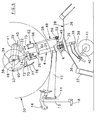
- the machine according to the embodiment of Figure 6 has a configuration general similar to that of Figures 1 to 5 and will therefore no longer be described in detail.
- the adjusting lever (43, 46) of the support axis (38) of the rotor (29, 30) of each side part (3, 4) of the frame (1) and the guide lever (63, 64) of the first section (57, 58) of each control rod (48, 49) are connected between them by cables (79 and 80).
- These are arranged in guide sleeves (81 and 82) which are fixed at each of their ends on plates (83 and 84) one of which is integral with the interior segment (19, 21) and the other with the exterior segment (20, 22) of the corresponding side part (3 or 4).
- one (80) of the cables (79 and 80) is fixed to the adjustment lever (43, 46) and to the lever guide (63, 70) in their parts which lie between their axes (38 and 67, 68) respective and their axes of articulation (50, 53 and 65, 66) on the sections (57 to 60).
- the fixing points of said cable (80) on the two levers (43, 46 and 63, 64) are located behind said axes (38 and 67, 68) (seen in the direction of advance A) and substantially the same distance from them.
- the other cable (79) is fixed on extensions (85, 86 and 87, 88) of the levers (43, 46 and 63, 64).
- extensions extend forward (seen in direction of travel A), beyond axes (38 and 67, 68).
- the fixing points of this cable (79) on said extensions (85 to 88) are located substantially at the same distance from the axes (38 and 67, 68) respectively.
- the length of the cables (79 and 80) is such that they can extend around the corresponding side part (3, 4) of the chassis (1) in the working position (see Figure 6).
- the machine described in connection with Figures 1 to 5 is intended for tedding.
- the rotors (27 to 30) are rotated around their axes respective supports (38), so that they rotate in pairs in convergence at the front (arrows F and F ').
- their forks (37) pick up on the front part of their trajectory the plants which are on the ground, entrain them backwards and spread them out again while causing them to overturn.
- the different rotors (27 to 30) can follow the unevenness of the ground by pivoting with the corresponding parts (2, 3 and 4) of the chassis (1) around the pivots (5 and 6).
- the entire chassis (1) can also pivot around the hinge pin (14) with the coupling bridge (15) so that the rotors (27 to 30) can properly follow the tractor. Furthermore, the two sections (57, 58 and 59, 60) of the rods control (48 and 49) of the support pins (38) of the rotors (29 and 30) of the lateral parts (3 and 4) are coupled together. Their attachment axes (75) are located then in the notches (76).
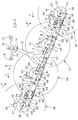
- the machine can be moved to the second working position shown in Figure 3 by operating the hydraulic cylinder (54) so that it shortens. It then moves the control rods (47, 48 and 49) to the side machine right. These drive all the adjustment levers (43 to 46) which rotate the support pins (38) on themselves. These axes (38) then orient the support wheels (41) towards the left side of the chassis (1) until they form angles of about 25 ° from their initial positions. However, being given that these support wheels (41) are automatically positioned in the direction advancement (A) when the machine is moved, the whole chassis (1) rotates around the hinge pin (14) of the coupling bridge (15) and takes an oblique position relative to the direction of advance (A). The rotors (27 to 30) are then also located on an oblique line and they move the plants in bias relative to the direction of advancement (A).
- the machine can also be transposed to a third position work which is not represented.
- the frame (1) In this position the frame (1) is inclined in a position opposite to that of FIG. 3. It is obtained by lengthening the jack hydraulic (54) when in the first working position.
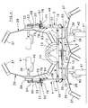
- the side parts (3 and 4) of the chassis (1) are raised in a substantially vertical position by means of the hydraulic cylinders (7 and 8). Then, the outer segments (20 and 22) of these side parts (3 and 4) are unlocked and turned about 180 ° around their geometric longitudinal axes (23 and 24) to bring the corresponding rotors (29 and 30) above the central part (2) with the forks (37) oriented towards the middle of the machine.
- the second sections (59 and 60) control rods (48 and 49) rotate with said outer segments (20 and 22).
- the plates (77) with the notches (76) then detach automatically attachment axes (75) of the first sections (57 and 58) (see figures 4 and 5).
- the machine according to the embodiment of Figure 6 can be transposed in the same working positions as those described above.
- the lateral parts (3 and 4) of the chassis (1) are also displaced in height and their outer segments (20 and 22) are rotated approximately 180 ° with the second sections (59 and 60) relative to the interior segments (19 and 21) and to the first sections (57 and 58).
- cables (79 and 80) maintain constantly said second sections (59 and 60) in the positions they occupied at the time of separation from the first sections (57 and 58).
- notches (76) of their plates (77) are located immediately at the level of the attachment pins (75) when returning to the working position, which facilitates the reestablishment of the link between the two sections (57, 58 and 59, 60).
- ends of the cables (79 and 80) which are connected to the outer segments (20 and 22) lateral parts (3 and 4) pivot with said segments (20 and 22) while traveling.
Landscapes
- Life Sciences & Earth Sciences (AREA)
- Environmental Sciences (AREA)
- Agricultural Machines (AREA)
- Compounds Of Unknown Constitution (AREA)
- Processes Of Treating Macromolecular Substances (AREA)
- Separation By Low-Temperature Treatments (AREA)
- Organic Low-Molecular-Weight Compounds And Preparation Thereof (AREA)
- Pharmaceuticals Containing Other Organic And Inorganic Compounds (AREA)
Description
- La figure 1 représente une vue arrière d'une machine selon l'invention dans une première position de travail.
- La figure 2 représente une vue de dessus de cette machine.
- La figure 3 représente une vue de dessus de la machine dans une deuxième position de travail.
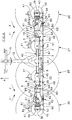
- La figure 4 représente une vue arrière de la machine en position de transport ou de dépose.
- La figure 5 représente une vue de côté de la machine selon la figure 4.
- La figure 6 représente une vue de dessus d'une machine selon un autre exemple de réalisation.
Claims (10)
- Machine de fenaison, notamment une faneuse de végétaux, qui peut être accouplée à un tracteur et qui comporte un châssis support (1) de forme allongée, se composant d'une partie centrale (2) et de deux parties latérales (3 et 4) qui sont articulées aux extrémités de ladite partie centrale (2) au moyen de pivots (5 et 6) autour desquels elles peuvent être déplacées en hauteur d'un angle d'environ 90° pour le transport, lequel châssis (1) porte plusieurs rotors (27 à 30) se situant sous la partie centrale (2) et les parties latérales (3 et 4) et pouvant être entraínés en rotation durant le travail autour d'axes supports (38) qui portent à leurs extrêmités inférieures des roues (41) d'appui au sol, chacune desdites parties latérales (3 et 4) étant réalisée en un segment intérieur (19, 21) et un segment extérieur (20, 22) qui porte le rotor (29, 30) correspondant et qui peut tourner autour de son axe longitudinal (23, 24) par rapport au segment intérieur (19, 21) pour amener ledit rotor (29, 30) sensiblement au-dessus de la partie centrale (2) avec les fourches de travail (37) orientées vers le milieu de la machine, lorsque lesdites parties latérales (3 et 4) sont déplacées en hauteur pour le transport, caractérisée par le fait que les axes supports (38) des rotors (27 à 30) sont montés pivotants dans des paliers du châssis (1) de la machine, que lesdits axes supports (38) comportent des leviers de réglage (43 à 46) qui sont reliés entre eux au moyen de tiges de commande (47, 48 et 49) et que les tiges de commande (48 et 49) des leviers de réglage (43 et 46) des axes supports (38) des deux rotors (29 et 30) des parties latérales (3 et 4) sont réalisées en un premier tronçon (57, 58) et un second tronçon (59, 60) qui sont munis de moyens (61 et 62) d'accouplement et de désaccouplement.
- Machine selon la revendication 1, caractérisée par le fait que le premier tronçon (57, 58) de chaque tige de commande (48, 49) est articulé sur la tige de commande (47) qui relie les leviers (44 et 45) des axes supports (38) des rotors (27 et 28) de la partie centrale (2) et sur un levier de guidage ( 63, 64) qui est articulé sur le segment intérieur (19, 21) de la partie latérale (3, 4) correspondante du châssis (1).
- Machine selon la revendication 1, caractérisée par le fait que le second tronçon (59, 60) de chaque tiges de commande (48, 49) est articulé sur le levier de réglage (43, 46) de l'axe support (38) du rotor (29, 30) de la partie latérale (3, 4) correspondante et sur un levier de guidage (69, 70) qui est sensiblement parallèle audit levier de réglage (43, 46) et qui est articulé sur le segment extérieur (20, 22) de la partie latérale (3, 4) du châssis (1).
- Machine selon la revendication 2, caractérisée par le fait que le premier tronçon (57, 58) de chaque tige de commande (48, 49) comporte un axe d'accrochage (75).
- Machine selon la revendication 4, catactérisée par le fait que l'axe d'accrochage (75) est dirigé dans la direction d'avancement (A).
- Machine selon les revendications 3 et 4, caractérisée par le fait que le second tronçon (59, 60) de chaque tige de commande (48, 49) comporte une plaque (77) avec une encoche (76) dans laquelle peut se loger l'axe d'accrochage (75) du premier tronçon (57, 58) correspondant.
- Machine selon la revendication 6, caractérisée par le fait que l'encoche (76) est en forme de V.
- Machine selon la revendication 6 ou 7, caractérisée par le fait qu 'au moins un des bords de l'encoche (76) est prolongé et constitue une rampe de guidage (78).
- Machine selon l'une quelconque des revendications précédentes, caractérisée par le fait que le levier de réglage (43, 46) de l'axe support (38) du rotor (29, 30) de chaque partie latérale (3, 4) du châssis (1) et le levier de guidage (63, 64) du premier tronçon (57, 58) de chaque tige de commande (48, 49) sont reliés entre eux par des câbles (79 et 80) placés dans des gaines de guidage (81 et 82) qui sont fixées à chacune de leurs extrémités sur des plaques (83 et 84) dont l'une (83) est solidaire du segment intérieur (19, 21) et l'autre (84) du segment extérieur (20, 22) de la partie latérale (3, 4) correspondante.
- Machine selon la revendication 9, caractérisée par le fait que le levier de réglage (43, 46) et le levier de guidage (63, 64) comportent des prolongements (85 à 88) qui s'étendent au-delà de leurs axes (38 et 67, 68) respectifs, un (79) des câbles (79, 80) étant relié auxdits prolongements (85 à 88) qui se situent devant lesdits axes (38 et 67, 68) et l'autre câble (80) étant relié aux parties des leviers (43, 46, 63, 64) qui se situent derrière lesdits axes (38 et 67, 68) (vu dans la direction d'avancement A).
Applications Claiming Priority (2)
| Application Number | Priority Date | Filing Date | Title |
|---|---|---|---|
| FR9503453 | 1995-03-20 | ||
| FR9503453A FR2731873B1 (fr) | 1995-03-20 | 1995-03-20 | Machine de fenaison, notamment une faneuse de vegetaux, transposable dans plusieurs positions |
Publications (2)
| Publication Number | Publication Date |
|---|---|
| EP0733302A1 EP0733302A1 (fr) | 1996-09-25 |
| EP0733302B1 true EP0733302B1 (fr) | 1999-09-22 |
Family
ID=9477371
Family Applications (1)
| Application Number | Title | Priority Date | Filing Date |
|---|---|---|---|
| EP96440024A Expired - Lifetime EP0733302B1 (fr) | 1995-03-20 | 1996-03-08 | Machine de fenaison |
Country Status (4)
| Country | Link |
|---|---|
| EP (1) | EP0733302B1 (fr) |
| AT (1) | ATE184744T1 (fr) |
| DE (1) | DE69604317T2 (fr) |
| FR (1) | FR2731873B1 (fr) |
Families Citing this family (3)
| Publication number | Priority date | Publication date | Assignee | Title |
|---|---|---|---|---|
| NL1006999C2 (nl) * | 1997-09-11 | 1999-03-12 | Maasland Nv | Opklapbare landbouwmachine alsmede werkwijze voor het vanuit de werkstand in de transportstand opklappen van die landbouwmachine. |
| FR2787286B1 (fr) * | 1998-12-18 | 2001-02-16 | Kuhn Sa | Machine de fenaison a commande hydraulique combinee pour le relevage des troncons lateraux ou l'orientation des roues |
| CN103828547A (zh) * | 2012-11-26 | 2014-06-04 | 烟台萨姆肯汽车配件制造有限公司 | 一种翻草机 |
Family Cites Families (6)
| Publication number | Priority date | Publication date | Assignee | Title |
|---|---|---|---|---|
| DE2419749A1 (de) * | 1974-04-24 | 1975-11-06 | Fella Werke Gmbh | Heuwerbungsmaschine |
| FR2582186B1 (fr) * | 1985-05-21 | 1989-05-05 | Kuhn Sa | Perfectionnement aux machines de fenaison munies de plusieurs roues rateleuses |
| DE8807510U1 (de) * | 1988-06-09 | 1989-07-06 | Alois Pöttinger Landmaschinen-Gesellschaft mbH, 8900 Augsburg | Heuwerbungsmaschine |
| DE4219484B4 (de) * | 1992-06-13 | 2005-03-17 | Alois Pöttinger Landmaschinen Gmbh | Heuwerbungsmaschine |
| DE9210001U1 (de) * | 1992-07-24 | 1992-09-24 | Greenland GmbH & Co KG, 7702 Gottmadingen | Landwirtschaftliche Maschine |
| FR2712767B1 (fr) * | 1993-11-23 | 1996-02-09 | Kuhn Sa | Machine de fenaison transposable dans plusieurs positions de travail. |
-
1995
- 1995-03-20 FR FR9503453A patent/FR2731873B1/fr not_active Expired - Fee Related
-
1996
- 1996-03-08 AT AT96440024T patent/ATE184744T1/de active
- 1996-03-08 EP EP96440024A patent/EP0733302B1/fr not_active Expired - Lifetime
- 1996-03-08 DE DE69604317T patent/DE69604317T2/de not_active Expired - Lifetime
Also Published As
| Publication number | Publication date |
|---|---|
| FR2731873A1 (fr) | 1996-09-27 |
| DE69604317D1 (de) | 1999-10-28 |
| FR2731873B1 (fr) | 1997-06-13 |
| DE69604317T2 (de) | 2000-04-20 |
| EP0733302A1 (fr) | 1996-09-25 |
| ATE184744T1 (de) | 1999-10-15 |
Similar Documents
| Publication | Publication Date | Title |
|---|---|---|
| FR2654893A1 (fr) | Machine agricole avec dispositif de suspension du groupe d'organes de travail perfectionne. | |
| EP0385899B1 (fr) | Machine de fenaison comportant plusieurs rotors | |
| FR2648310A1 (fr) | Machine agricole pour l'andainage, comportant des bras porte-outils repliables | |
| EP1290936A1 (fr) | Machine de fenaison | |
| FR2746576A1 (fr) | Machine agricole du genre faneuse a rateaux rotatifs multiples, convertible d'une position de travail deployee a une position de transport ramassee | |
| EP1142468B1 (fr) | Machine de fenaison | |
| EP0310532B2 (fr) | Machine de fenaison avec un dispositif de protection perfectionné | |
| EP0733302B1 (fr) | Machine de fenaison | |
| FR2664127A1 (fr) | Machine agricole, notamment une andaineuse de vegetaux, a largeur de travail reglable. | |
| EP0797913B1 (fr) | Machine de fenaison | |
| EP0554200B1 (fr) | Machine de fenaison comportant un châssis avec des roues porteuses commandées | |
| EP0857413A1 (fr) | Machine de fenaison | |
| EP0536071B1 (fr) | Machine de fenaison, notamment une faneuse de végétaux, avec au moins deux positions de travail | |
| EP0426588A1 (fr) | Perfectionnement aux machines agricoles destinées notamment à la fenaison | |
| EP0654209B1 (fr) | Machine de fenaison | |
| EP0593378B1 (fr) | Machine de fenaison pour l'andainage de fourrage | |
| EP0772970B1 (fr) | Machine de fenaison, notamment une faneuse | |
| EP1013161B1 (fr) | Machine de fenaison | |
| EP0914766B1 (fr) | Machine de fenaison | |
| EP0779022A1 (fr) | Machine de fenaison | |
| EP0486415B1 (fr) | Faucheuse à châssis indépendant comportant un dispositif de suspension et un dispositif d'allègement perfectionnés | |
| EP0442833B1 (fr) | Machine de fenaison avec dispositif de protection perfectionné | |
| EP0811314B1 (fr) | Machine agricole | |
| FR2699044A1 (fr) | Machine de fenaison avec des roues de transport déplaçables en hauteur. | |
| EP0617883A1 (fr) | Machine de fenaison, notamment une faneuse |
Legal Events
| Date | Code | Title | Description |
|---|---|---|---|
| PUAI | Public reference made under article 153(3) epc to a published international application that has entered the european phase |
Free format text: ORIGINAL CODE: 0009012 |
|
| AK | Designated contracting states |
Kind code of ref document: A1 Designated state(s): AT DE FR IT NL |
|
| 17P | Request for examination filed |
Effective date: 19970224 |
|
| GRAG | Despatch of communication of intention to grant |
Free format text: ORIGINAL CODE: EPIDOS AGRA |
|
| GRAG | Despatch of communication of intention to grant |
Free format text: ORIGINAL CODE: EPIDOS AGRA |
|
| GRAH | Despatch of communication of intention to grant a patent |
Free format text: ORIGINAL CODE: EPIDOS IGRA |
|
| 17Q | First examination report despatched |
Effective date: 19990305 |
|
| GRAH | Despatch of communication of intention to grant a patent |
Free format text: ORIGINAL CODE: EPIDOS IGRA |
|
| GRAA | (expected) grant |
Free format text: ORIGINAL CODE: 0009210 |
|
| AK | Designated contracting states |
Kind code of ref document: B1 Designated state(s): AT DE FR IT NL |
|
| REF | Corresponds to: |
Ref document number: 184744 Country of ref document: AT Date of ref document: 19991015 Kind code of ref document: T |
|
| ITF | It: translation for a ep patent filed | ||
| REF | Corresponds to: |
Ref document number: 69604317 Country of ref document: DE Date of ref document: 19991028 |
|
| PLBE | No opposition filed within time limit |
Free format text: ORIGINAL CODE: 0009261 |
|
| STAA | Information on the status of an ep patent application or granted ep patent |
Free format text: STATUS: NO OPPOSITION FILED WITHIN TIME LIMIT |
|
| 26N | No opposition filed | ||
| PGFP | Annual fee paid to national office [announced via postgrant information from national office to epo] |
Ref country code: NL Payment date: 20110225 Year of fee payment: 16 Ref country code: IT Payment date: 20110226 Year of fee payment: 16 Ref country code: AT Payment date: 20110221 Year of fee payment: 16 |
|
| PGFP | Annual fee paid to national office [announced via postgrant information from national office to epo] |
Ref country code: FR Payment date: 20110412 Year of fee payment: 16 Ref country code: DE Payment date: 20110308 Year of fee payment: 16 |
|
| REG | Reference to a national code |
Ref country code: NL Ref legal event code: V1 Effective date: 20121001 |
|
| REG | Reference to a national code |
Ref country code: AT Ref legal event code: MM01 Ref document number: 184744 Country of ref document: AT Kind code of ref document: T Effective date: 20120308 |
|
| REG | Reference to a national code |
Ref country code: FR Ref legal event code: ST Effective date: 20121130 |
|
| REG | Reference to a national code |
Ref country code: DE Ref legal event code: R119 Ref document number: 69604317 Country of ref document: DE Effective date: 20121002 |
|
| PG25 | Lapsed in a contracting state [announced via postgrant information from national office to epo] |
Ref country code: FR Free format text: LAPSE BECAUSE OF NON-PAYMENT OF DUE FEES Effective date: 20120402 Ref country code: AT Free format text: LAPSE BECAUSE OF NON-PAYMENT OF DUE FEES Effective date: 20120308 |
|
| PG25 | Lapsed in a contracting state [announced via postgrant information from national office to epo] |
Ref country code: IT Free format text: LAPSE BECAUSE OF NON-PAYMENT OF DUE FEES Effective date: 20120308 |
|
| PG25 | Lapsed in a contracting state [announced via postgrant information from national office to epo] |
Ref country code: NL Free format text: LAPSE BECAUSE OF NON-PAYMENT OF DUE FEES Effective date: 20121001 |
|
| PG25 | Lapsed in a contracting state [announced via postgrant information from national office to epo] |
Ref country code: DE Free format text: LAPSE BECAUSE OF NON-PAYMENT OF DUE FEES Effective date: 20121002 |