EP0303566A2 - Abdeckung für Baufugen - Google Patents
Abdeckung für Baufugen Download PDFInfo
- Publication number
- EP0303566A2 EP0303566A2 EP88810475A EP88810475A EP0303566A2 EP 0303566 A2 EP0303566 A2 EP 0303566A2 EP 88810475 A EP88810475 A EP 88810475A EP 88810475 A EP88810475 A EP 88810475A EP 0303566 A2 EP0303566 A2 EP 0303566A2
- Authority
- EP
- European Patent Office
- Prior art keywords
- hollow flat
- flat profile
- joint
- cover according
- hollow
- Prior art date
- Legal status (The legal status is an assumption and is not a legal conclusion. Google has not performed a legal analysis and makes no representation as to the accuracy of the status listed.)
- Granted
Links
Images
Classifications
-
- E—FIXED CONSTRUCTIONS
- E04—BUILDING
- E04B—GENERAL BUILDING CONSTRUCTIONS; WALLS, e.g. PARTITIONS; ROOFS; FLOORS; CEILINGS; INSULATION OR OTHER PROTECTION OF BUILDINGS
- E04B1/00—Constructions in general; Structures which are not restricted either to walls, e.g. partitions, or floors or ceilings or roofs
- E04B1/62—Insulation or other protection; Elements or use of specified material therefor
- E04B1/66—Sealings
- E04B1/68—Sealings of joints, e.g. expansion joints
- E04B1/6803—Joint covers
Definitions
- the invention relates to a cover for construction joints, in particular construction joints of a vertical type, consisting of a hollow flat profile made of light metal, which can be extended as desired with lugs, with clamping devices distributed along the hollow flat profile, connected to it and projecting into the construction joint and spreading between the joint walls.
- the hollow flat profile has a preferably dovetail-shaped guide ridge on its hollow side and a groove on the apex of the guide ridge.
- the groove serves to center the bore of the fastening screw, which is turned by the hollow flat profile into an expandable clamping device that can be clamped between the joint walls of the building joint.
- the clamping device is centered by the guide burr and guided by the dovetail so that it remains connected to the hollow flat profile.
- the hollow flat profiles have a pre-assembled length.
- hollow flat profiles of any length from this unit length, which serve as a waterproof cover their ends are shaped like a letter.
- the joints of the hollow flat profiles become overhanging.
- the A connecting and guiding element is placed on the ends of the two hollow flat profiles at the joint on the guide ridge of the hollow flat profiles.
- the cover After inserting the cover into the construction joint, the cover is pressed against the edge areas of the construction joint and the clamping screw is screwed in and tensioned.
- the hollow flat profile is supported in a bridge-like manner on the contact surface of its outer edges. Due to the movement of the screw, the clamping device is clamped between the walls of the construction joint and the hollow flat profile is pressed against the edge areas of the construction so that the cover can prevent the penetration of meteor water.
- Modern buildings are constructed in such a way that the length of the building is changed using so-called construction joints. Thanks to this technology, there are no excessive tensions in the structure of the building, which would otherwise result in mechanical destruction of the building material by overstressing it.
- the planned separation of the walls of a building into elements a few meters wide by approx. 9 to 28 mm wide, vertical construction joints enables uncontrolled cracks and gaps in the building to be avoided.
- the construction joints planned in advance are designed to prevent the ingress of weather by filling the Construction joint sealed with plastic-elastic materials. Due to their function, the fillers of the construction joint are exposed to weathering. Over time, these weather influences cause the joint seal to decompose, degrade and disintegrate.
- the invention can remedy this.
- the invention as characterized in the claims solves the Task by a protective cover of the construction joint, consisting of a hollow profile made of corrosion-resistant light metal, which can be extended as required, and distributed along the hollow profile, connected to it and spreadable between the joint walls.
- the hollow flat profile has a preferably dovetail-shaped guide ridge on its hollow side and a groove on the apex of the guide ridge. The groove serves to center the bore of the clamping screw, which is turned by the hollow flat profile into an expandable clamping device that can be clamped between the joint walls of the building joint.
- the clamping device is centered by the guide ridge and guided by the dovetail shape of the guide ridge in such a way that it remains displaceably connected to the hollow flat profile, and thus simplifies the process when loading the clamping device with the clamping screw.
- the ends of the hollow flat profiles are shaped like a letter.
- a guide element is placed on the ends of the hollow flat profiles on the guide ridge.
- This guide element encompasses the guide ridge into the dovetail guide and remains firmly in place by a suitable fit. Since the edges of the hollow flat profiles are broken, a narrow contact surface is created on the hollow flat profile edge. This contact surface is pressed against the edge areas of the construction joint by tightening the clamping screws.
- the advantages achieved by the invention can be seen both in the excellent aging resistance of the cover and thus in the construction joints and in rationalization effects. Filling materials such as rubber and putty and their laying or. Processing can be saved.
- the cover can be laid with the simplest of tools, such as a pocket knife and screwdriver, by cutting a recess from the plastic foam filling in the construction joint. It is not necessary to fill and seal the construction joint, because should water come into the construction joint contrary to expectations, it runs freely through gravity through the gap in the construction joint. Since the construction joint is constantly drained in this way, the basis for frost damage is missing.
- the application of the invention is suitable both for new buildings and for renovation measures. The invention is thus an effective prophylaxis and therapy method for modern ecological and economical construction.
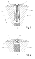
- the cover 1 shown in FIG. 1 bridges the gap formed by the components 11 and 12 through the hollow flat profile 2.
- Such a gap is called construction joint and is filled with plastic foam 13 except for the clamping device 3, consisting of the expansion body 4 and the wedge 5 and the clamping screw 6 placed therein.
- the non-positive system of anchoring the cover 1 is shown.
- the clamping screw 6 is tightened, the wedge 5 is pulled against the hollow flat profile 2, thereby spreading the clamp 4 so that it contacts the components 11 and 12 and thus the components formed by them Walls of the construction joint is pressed.
- the hollow flat profile 2 is pressed against the outer surfaces of the wall elements 11, 12.
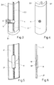
- the clamping screw 6 generates a bending stress in the bridge-like hollow flat profile 2, which results in the pressing and sealing of the support surfaces 2.4 (see FIG. 3) on the components 11 and 12. 3 and 4, the cover 1 of FIG. 1 is shown in a graphic representation.
- the face 10 'and 10 ⁇ of the hollow flat profile are clearly visible.
- 5 and 6 show the two face surfaces 10 'and 10 slaughter of two abutting hollow flat profiles 2' and 2 ⁇ , a guide element 8 being inserted on the guide ridge 2.2 (cf. FIG. 4).
- a groove 2.3 is formed on the guide ridge 2.2 (cf. FIG. 4).
- the dovetail-shaped design of the guide ridge 2.2 of the hollow flat profile 2 is shown in FIG. 2.
- the guide element 8 clings to the guide ridge 2.2. This ensures that the abutting face surfaces 10 'and 10 ⁇ of the hollow flat profiles 2' and 2 ⁇ overlap each other with sufficient precision, to be waterproof (see Fig. 5 and Fig. 6).
Landscapes
- Engineering & Computer Science (AREA)
- Architecture (AREA)
- Physics & Mathematics (AREA)
- Electromagnetism (AREA)
- Civil Engineering (AREA)
- Structural Engineering (AREA)
- Building Environments (AREA)
- Finishing Walls (AREA)
Abstract
Description
- Die Erfindung betrifft eine Abdeckung für Baufugen, insbesondere Baufugen senkrechter Art, bestehend aus einem durch Ansätze beliebig verlängerbaren Hohlflachprofil aus Leichtmetall mit entlang dem Hohlflachprofil verteilten, mit diesem verbundenen und in die Baufuge hineinragenden und zwischen die Fugenwände spreizbaren Klemmvorrichtungen. Dabei weist das Hohlflachprofil einen vorzugsweise schwalbenschwanzförmigen Führungsgrat auf seiner Hohlseite und eine Rille am Scheitel des Führungsgrates auf. Die Rille dient zur Zentrierung der Bohrung der Befestigungsschraube, die vom Hohlflachprofil in eine spreizbare, zwischen die Fugenwände der Baufuge klemmbare Klemmvorrichtung gedreht wird. Durch den Führungsgrat wird die Klemmvorrichtung zentriert und durch den Schwalbenschwanz desselben so geführt, dass diese mit dem Hohlflachprofil verbunden bleibt. Die Hohlflachprofile weisen eine konfektionierte Länge auf. Um aus dieser Einheitslänge beliebig lange und als wasserdichte Abdeckung dienende Hohlflachprofile zu erhalten, werden ihre Enden schiftartig ausgebildet. Somit werden die Stösse der Hohlflachprofile überhängend. Zwecks Genauigkeit dieser Passung wird bei der Montage auf die Enden der zwei Hohlflachprofile der Stoss-Stelle auf den Führungsgrat der Hohlflachprofile ein Verbindungs- und zugleich Führungselement gesetzt. Nach dem Hineinfügen der Abdeckung in die Baufuge wird die Abdeckung gegen die Randbereiche der Baufuge gedrückt und die Klemmschraube eingedreht und gespannt. Dabei stützt sich das Hohlflachprofil auf die Auflagefläche seiner äusseren Ränder brückenartig ab. Durch die Bewegung der Schraube wird die Klemmvorrichtung zwischen die Wände der Baufuge geklemmt und das Hohlflachprofil an die Randbereiche der Baufage so angepresst, das die Abdeckung das Eindringen von Meteor-Wasser verhindern kann.
- Moderne Bauten werden so erstellt, dass für die Längenveränderung der Baukörper durch sogenannte Baufugen vorgesorgt wird. Dank dieser Technik entstehen keine übermässigen Spannungen in der Struktur des Baus, die sich sonst durch Ueberbeanspruchung des Baumaterials in mechanischer Zerstörung desselben äussern. Mit anderen Worten, die geplante Trennung der Wände eines Baus in Elemente von einigen Metern Breite durch ca. 9 bis 28 mm breite, senkrecht verlaufende Baufugen ermöglicht die Vermeidung von unkontrollierten Rissen und Spalten im Bauobjekt. Die zum voraus geplanten Baufugen werden gegen das Eindringen von Wettereinflüssen durch das Füllen der Baufuge mit plastisch-elastischen Werkstoffen abgedichtet. Bedingt durch ihre Funktion, werden die Füllstoffe der Baufuge der Verwitterung ausgesetzt. Im Laufe der Zeit bewirken diese Einflüsse des Wetters Zersetzung, Abbau und Zerfall der Fugendichtung. Diese Schäden entstehen nebst alterungsbedingtem Abbau der Elastomere und der Polymere durch fortschreitende Frostschäden, die überall dort vorkommen, wo das Eindringen von Wasser und das anschliessende Auftreten von Gefriertemperaturen nicht zu vermeiden sind. Gemäss dem Stand der Tecknik werden die Fugen so erstellt, das der Inhalt der Fuge durch eine Kunststoffschaumplatte belegt wird. Am Schluss wird die äussere Peripherie der Fugenfüllung mit Kitt gefüllt. Dieser Kitt hat als Dichtung die Aufgabe, das Eindringen von Wasser zu vermeiden. Um die Kittmenge (z.B. aus Silicon) und deren Verarbeitung zu reduzieren, werden vielfach zusätzlich Gummiprofile, insbesondere Moosgummischnüre, in die äussere Peripherie der Baufuge gelegt. Die Verwitterung der äusseren Kittschicht dauert erfahrungsgemäss wenige Jahre, so dass das Eindringen von Wasser in die Baufuge trotz all dieser Massnahmen des Stands der Technik vorprogrammiert ist.
- Hier kann die Erfindung Abhilfe schaffen. Die Erfindung, wie sie in den Ansprüchen gekennzeichnet ist, löst die Aufgabe durch eine schützende Abdeckung der Baufuge, bestehend aus einem durch Ansätze beliebig verlängerbaren Hohlprofil aus korrosionsfestem Leichtmetall und entlang dem Hohlprofil verteilten, mit diesem verbundenen und zwischen die Fugenwände spreizbaren Klemmvorrichtungen. Dabei weist das Hohlflachprofil einen vorzugsweise schwalbenschwanzförmigen Führungsgrat auf seiner Hohlseite und am Scheitel des Führungsgrates eine Rille auf. Die Rille dient zur Zentrierung der Bohrung der Klemmschraube, die vom Hohlflachprofil in eine spreizbare, zwischen die Fugenwände der Baufuge klemmbare Klemmvorrichtung gedreht wird. Die Klemmvorrichtung wird durch den Führungsgrat zentriert und durch die Schwalbenschwanzform des Führungsgrates so geführt, dass diese mit dem Hohlflachprofil verschiebbar verbunden bleibt, und somit den Vorgang beim Bestücken der Klemmvorrichtung mit der Klemmschraube vereinfacht. Um aus den Hohlflachprofilen konfektionierter Länge beliebig lange und gegen Niederschläge dichte Abdeckungen zu erhalten, werden die Enden der Hohlflachprofile schiftartig ausgebildet. Diese geschifteten Stösse lassen die Verkürzung oder Verlängerung der Hohlflachprofile infolge von Temperaturwechseln zu, indem diese sich schuppenartig aufeinander bewegen können. Zugleich wird durch die Präzision der Schiftung die Distanz der Profile zueinander eng gehalten, so dass das Eindringen von Niederschlag auf diese Weise ausge schlossen wird. Um die Präzision der Schiftstelle bei der Montage ohne Mühe zu erhalten, wird an die Enden der Hohlflachprofile auf den Führungsgrat ein Führungselement gesteckt. Dieses Führungselement umgreift den Führungsgrat bis in die Schwalbenschwanzführung und bleibt durch geeignete Passung an die Stoss-Stelle fest. Da die Ränder der Hohlflachprofile gebrochen sind, entsteht am Hohlflachprofilrand eine schmale Auflagefläche. Diese Auflagefläche wird gegen die Randbereiche der Baufuge durch das Anziehen ker Klemmschrauben gepresst.
- Es versteht sich, dass wetter- und korrosionsfeste Werkstoffe für Abdeckungen dieser Art und somit für die Hohlflachprofile bevorzugt werden. So eignen sich besonders gut entsprechende Aluminiumlegierungen, die zugleich via Extrusion preiswert zu verarbeiten sind. Da blanke Metallflächen höchst selten aus ästhetischen Gründen am Bauobjekt erwünscht sind, werden die Hohlflachprofile bei ihrer Herstellung mit einer Grundierung versehen. Besonders günstig erweisen sich Grundierungen mit zwei Komponenten Epoxidharzen, die sich für die Nachbehandlung mit verschiedenen Farben, darunter Dispersionsfarben, eignen.
- Die durch die Erfindung erreichten Vorteile sind sowohl in der hervorragenden Alterungsbeständigkeit der Abdeckung und somit der Baufugen wie in Rationalisierungseffekten zu sehen. Dabei kann an Füllmaterialien wie Gummi und Kitt und deren Verlegung resp. Verarbeitung gespart werden. Die Abdeckung kann mit einfachsten Mitteln wie Sackmesser und Schraubenzieher verlegt werden, indem aus der Kunststoffschaumfüllung der Baufuge eine Aussparung geschnitten wird. Das Füllen und Versiegeln der Baufuge ist nicht erforderlich, denn sollte wider Erwarten Wasser in die Baufuge gelangen, so läuft dieses ungehindert der Schwerkraft folgend durch den Spalt der Baufuge ab. Da die Baufuge auf diese Art stetig entwässert wird, fehlen die Grundlagen für Frostschäden. Die Anwendung der Erfindung eignet sich sowohl für Neubauten wie für Sanierungsmassnahmen. Die Erfindung ist somit eine wirksame Prophylaxe sowie Therapiemethode für modernes ökologisches und ökonomisches Bauen.
- Im folgenden wird die Erfindung anhand einer, lediglich einen Ausführungsweg darstellenden Zeichnung näher erläutert. Es zeigt:
- Fig. 1 einen Querschnitt der Baufuge mit Abdeckung,
- Fig. 2 einen Querschnitt der Baufuge in unmittelbarer Nähe eines Stosses, mit dem Führungselement,
- Fig. 3 ein Abdeckungselement (aus darstellungstechnischen Gründen stark verkürzt) von hinten,
- Fig. 4 dasselbe Abdeckungselement wie in Figur 3 von vorne.
- Fig. 5 die Stoss-Stelle der Abdeckung von hinten,
- Fig. 6 die Stoss-Stelle der Abdeckung von Fig. 5 in Seitenansicht.
- Die in Fig. 1 gezeigte Abdeckung 1 überbrückt durch das Hohlflachprofil 2 den von den Bauelementen 11 und 12 gebildeten Spalt. So ein Spalt wird Baufuge genannt und ist mit Kunststoffschaum 13 bis auf die Klemmvorrichtung 3, bestehend aus dem Spreizkörper 4 und dem darin plazierten Keil 5 und der Klemmschraube 6, ausgefüllt. Dabei wird das kraftschlüssige System der Verankerung der Abdeckung 1 gezeigt. Bei Anziehen der Klemmschraube 6 wird der Keil 5 gegen das Hohlflachprofil 2 gezogen und dadurch die Klemme 4 so gespreizt, dass sie an die Bauelemente 11 und 12 und somit die durch diese gebildeten Wände der Baufuge angepresst wird. Zugleich wird das Hohlflachprofil 2 gegen die Aussenflächen der Wandelemente 11, 12 angedrückt. Dabei erzeugt die Klemmschraube 6 im brückenartigen Hohlflachprofil 2 eine Biegespannung, die das Anpressen und Dichten der Auflagenflächen 2.4 (vgl. Fig. 3) an den Bauelementen 11 und 12 zur Folge hat. In Fig. 3 und 4 wird die Abdeckung 1 der Fig. 1 in bildlicher Darstellung gezeigt. Dabei sind die Schiftflächen 10′ und 10˝ des Hohlflachprofils gut ersichtlich. Im zusammengebauten Zustand zeigen die Fig. 5 und 6 die zwei Schiftflächen 10′ und 10˝ von zwei aneinander anstossenden Hohlflachprofilen 2′ und 2˝, wobei am Führungsgrat 2.2 (vgl. Fig. 4) ein Führungselement 8 gesteckt ist. Um das Bohren der Löcher für die Klemmschraube 6 (vgl. Fig. 1 und 4) zu erleichtern, wird am Führungsgrat 2.2 (vgl. Fig. 4) eine Rille 2.3 geformt. Die schwalbenschwanzförmige Ausbildung des Führungsgrates 2.2 des Hohlflachprofils 2 zeigt Fig. 2. An den Führungsgrat 2.2 klammert sich das Führungselement 8. Dieser sorgt dafür, dass die anstossenden Schiftflächen 10′ und 10˝ der Hohlflachprofile 2′ und 2˝ mit ausreichender Präzision einander überdecken, um wasserdicht zu sein (vgl. Fig. 5 und Fig. 6).
Claims (9)
Priority Applications (1)
| Application Number | Priority Date | Filing Date | Title |
|---|---|---|---|
| AT88810475T ATE94932T1 (de) | 1987-08-10 | 1988-07-11 | Abdeckung fuer baufugen. |
Applications Claiming Priority (2)
| Application Number | Priority Date | Filing Date | Title |
|---|---|---|---|
| CH3058/87 | 1987-08-10 | ||
| CH3058/87A CH674232A5 (de) | 1987-08-10 | 1987-08-10 |
Publications (3)
| Publication Number | Publication Date |
|---|---|
| EP0303566A2 true EP0303566A2 (de) | 1989-02-15 |
| EP0303566A3 EP0303566A3 (en) | 1989-09-20 |
| EP0303566B1 EP0303566B1 (de) | 1993-09-22 |
Family
ID=4247669
Family Applications (1)
| Application Number | Title | Priority Date | Filing Date |
|---|---|---|---|
| EP88810475A Expired - Lifetime EP0303566B1 (de) | 1987-08-10 | 1988-07-11 | Abdeckung für Baufugen |
Country Status (4)
| Country | Link |
|---|---|
| EP (1) | EP0303566B1 (de) |
| AT (1) | ATE94932T1 (de) |
| CH (1) | CH674232A5 (de) |
| DE (1) | DE3884311D1 (de) |
Cited By (2)
| Publication number | Priority date | Publication date | Assignee | Title |
|---|---|---|---|---|
| WO1994021875A1 (de) * | 1993-03-15 | 1994-09-29 | Hans Santer | Abdichtung von bodenfugen |
| RU2308580C2 (ru) * | 2005-06-09 | 2007-10-20 | Леонид Константинович Матросов | Держатель растворного шва |
Family Cites Families (4)
| Publication number | Priority date | Publication date | Assignee | Title |
|---|---|---|---|---|
| DE1658994A1 (de) * | 1967-06-05 | 1970-12-10 | Walter Tholl | Watho-Dehnungsfugenprofil fuer Fussboeden,Verblendmauerwerk und Sichtbeton |
| US3439463A (en) * | 1967-12-01 | 1969-04-22 | Joseph F Matarese | Expansion and control joint cover |
| DE1683299B1 (de) * | 1967-12-01 | 1970-09-03 | Hammerschmidt & Co Migua | Abdeckleiste aus nachgiebigem Material |
| DD110534A2 (de) * | 1973-12-28 | 1974-12-20 |
-
1987
- 1987-08-10 CH CH3058/87A patent/CH674232A5/de not_active IP Right Cessation
-
1988
- 1988-07-11 AT AT88810475T patent/ATE94932T1/de not_active IP Right Cessation
- 1988-07-11 EP EP88810475A patent/EP0303566B1/de not_active Expired - Lifetime
- 1988-07-11 DE DE88810475T patent/DE3884311D1/de not_active Expired - Fee Related
Cited By (2)
| Publication number | Priority date | Publication date | Assignee | Title |
|---|---|---|---|---|
| WO1994021875A1 (de) * | 1993-03-15 | 1994-09-29 | Hans Santer | Abdichtung von bodenfugen |
| RU2308580C2 (ru) * | 2005-06-09 | 2007-10-20 | Леонид Константинович Матросов | Держатель растворного шва |
Also Published As
| Publication number | Publication date |
|---|---|
| EP0303566B1 (de) | 1993-09-22 |
| CH674232A5 (de) | 1990-05-15 |
| DE3884311D1 (de) | 1993-10-28 |
| ATE94932T1 (de) | 1993-10-15 |
| EP0303566A3 (en) | 1989-09-20 |
Similar Documents
| Publication | Publication Date | Title |
|---|---|---|
| EP1001178A2 (de) | Gasbeton-Schraube | |
| EP3477012B1 (de) | Haltevorrichtung zur befestigung einer brüstungs- oder geländerplatte | |
| DE19519219A1 (de) | Holz-Aluminium-Pfosten-Riegelkonstruktion | |
| EP0303566B1 (de) | Abdeckung für Baufugen | |
| AT507318B1 (de) | Sockelprofilleiste für dämmplatten | |
| DE10359089B3 (de) | Freitragendes Vordach | |
| DE9107171U1 (de) | Pfosten- und Riegelprofilgerüst für eine mit Flächenelementen ausgefachte Wand- oder Deckenkonstruktion | |
| DE102012223184A1 (de) | Verfahren und Vorrichtung zur Montage von Lichtschächten | |
| DE102016125025C5 (de) | Verwendung einer Befestigungseinrichtung zur Befestigung von Kappleisten, insbesondere an einer Wärmedämmung | |
| DE202014103130U1 (de) | Verschalung für Gebäudeteile | |
| DE10361083A1 (de) | Anordnung und Verfahren zum Abdichten von Fugen an Bauwerken, insbesondere von Dehnfugen in einer Außenfassade | |
| DE69532105T2 (de) | Draht-Eckleiste für Putz, Stukko oder dergleichen | |
| DE2011263C3 (de) | Streifenförmiges Abschlußelement für Hohlwände zur Befestigung von Tür- oder Fensterrahmen | |
| DE3221615A1 (de) | Wandanschluss-klemmprofil | |
| EP3653805B1 (de) | Anschlussprofil | |
| EP3276100A1 (de) | Abdichtsystem für ein wandungssystem | |
| DE9217152U1 (de) | Fugenband | |
| DE102017117264A1 (de) | Wandanschlußsystem | |
| EP1557520A2 (de) | Laibungsanschlussprofil für an putz angrenzende bauteile | |
| DE8216635U1 (de) | Wandanschluß-Klemmprofil | |
| DE202004016369U1 (de) | Dichtstück zur Durchführung von Kabeln und Fassade oder Lichtdach | |
| DE102007025153B4 (de) | Rahmen für Isolierglasscheiben | |
| WO1994021875A1 (de) | Abdichtung von bodenfugen | |
| DE29705216U1 (de) | Abdeckung für eine Fensterbrüstung | |
| DE10337953A1 (de) | Glasaufnahmeprofil zum Einbau einer Isolierglassscheibe in einen Zwischenraum einer Tragkonstruktion |
Legal Events
| Date | Code | Title | Description |
|---|---|---|---|
| PUAI | Public reference made under article 153(3) epc to a published international application that has entered the european phase |
Free format text: ORIGINAL CODE: 0009012 |
|
| AK | Designated contracting states |
Kind code of ref document: A2 Designated state(s): AT DE FR IT |
|
| 17P | Request for examination filed |
Effective date: 19890331 |
|
| PUAL | Search report despatched |
Free format text: ORIGINAL CODE: 0009013 |
|
| AK | Designated contracting states |
Kind code of ref document: A3 Designated state(s): AT DE FR IT |
|
| 17Q | First examination report despatched |
Effective date: 19910423 |
|
| GRAA | (expected) grant |
Free format text: ORIGINAL CODE: 0009210 |
|
| AK | Designated contracting states |
Kind code of ref document: B1 Designated state(s): AT DE FR IT |
|
| REF | Corresponds to: |
Ref document number: 94932 Country of ref document: AT Date of ref document: 19931015 Kind code of ref document: T |
|
| ITF | It: translation for a ep patent filed | ||
| REF | Corresponds to: |
Ref document number: 3884311 Country of ref document: DE Date of ref document: 19931028 |
|
| ET | Fr: translation filed | ||
| PLBE | No opposition filed within time limit |
Free format text: ORIGINAL CODE: 0009261 |
|
| STAA | Information on the status of an ep patent application or granted ep patent |
Free format text: STATUS: NO OPPOSITION FILED WITHIN TIME LIMIT |
|
| 26N | No opposition filed | ||
| PGFP | Annual fee paid to national office [announced via postgrant information from national office to epo] |
Ref country code: FR Payment date: 19970730 Year of fee payment: 10 |
|
| PGFP | Annual fee paid to national office [announced via postgrant information from national office to epo] |
Ref country code: DE Payment date: 19970808 Year of fee payment: 10 |
|
| PGFP | Annual fee paid to national office [announced via postgrant information from national office to epo] |
Ref country code: AT Payment date: 19970814 Year of fee payment: 10 |
|
| PG25 | Lapsed in a contracting state [announced via postgrant information from national office to epo] |
Ref country code: AT Free format text: LAPSE BECAUSE OF NON-PAYMENT OF DUE FEES Effective date: 19980711 |
|
| PG25 | Lapsed in a contracting state [announced via postgrant information from national office to epo] |
Ref country code: FR Free format text: LAPSE BECAUSE OF NON-PAYMENT OF DUE FEES Effective date: 19990331 |
|
| PG25 | Lapsed in a contracting state [announced via postgrant information from national office to epo] |
Ref country code: DE Free format text: LAPSE BECAUSE OF NON-PAYMENT OF DUE FEES Effective date: 19990501 |
|
| REG | Reference to a national code |
Ref country code: FR Ref legal event code: ST |
|
| PG25 | Lapsed in a contracting state [announced via postgrant information from national office to epo] |
Ref country code: IT Free format text: LAPSE BECAUSE OF NON-PAYMENT OF DUE FEES;WARNING: LAPSES OF ITALIAN PATENTS WITH EFFECTIVE DATE BEFORE 2007 MAY HAVE OCCURRED AT ANY TIME BEFORE 2007. THE CORRECT EFFECTIVE DATE MAY BE DIFFERENT FROM THE ONE RECORDED. Effective date: 20050711 |