EP0296437B1 - Entgasungsverschluss für Flüssigkeitsbehälter - Google Patents
Entgasungsverschluss für Flüssigkeitsbehälter Download PDFInfo
- Publication number
- EP0296437B1 EP0296437B1 EP88109343A EP88109343A EP0296437B1 EP 0296437 B1 EP0296437 B1 EP 0296437B1 EP 88109343 A EP88109343 A EP 88109343A EP 88109343 A EP88109343 A EP 88109343A EP 0296437 B1 EP0296437 B1 EP 0296437B1
- Authority
- EP
- European Patent Office
- Prior art keywords
- closure
- liquid
- adsorbent
- housing
- degassing
- Prior art date
- Legal status (The legal status is an assumption and is not a legal conclusion. Google has not performed a legal analysis and makes no representation as to the accuracy of the status listed.)
- Expired - Lifetime
Links
- 239000007788 liquid Substances 0.000 title claims description 35
- 239000003463 adsorbent Substances 0.000 claims description 20
- 239000000463 material Substances 0.000 claims description 9
- 239000003795 chemical substances by application Substances 0.000 claims description 3
- 230000003472 neutralizing effect Effects 0.000 claims description 3
- 238000012856 packing Methods 0.000 claims 2
- 238000013022 venting Methods 0.000 claims 2
- 238000007872 degassing Methods 0.000 description 17
- OKTJSMMVPCPJKN-UHFFFAOYSA-N Carbon Chemical compound [C] OKTJSMMVPCPJKN-UHFFFAOYSA-N 0.000 description 6
- 239000002245 particle Substances 0.000 description 6
- 238000005299 abrasion Methods 0.000 description 5
- 239000004033 plastic Substances 0.000 description 5
- 229920003023 plastic Polymers 0.000 description 5
- 239000007789 gas Substances 0.000 description 4
- 238000004519 manufacturing process Methods 0.000 description 3
- 239000004065 semiconductor Substances 0.000 description 3
- 229920001774 Perfluoroether Polymers 0.000 description 2
- 238000011109 contamination Methods 0.000 description 2
- 239000012535 impurity Substances 0.000 description 2
- 239000002808 molecular sieve Substances 0.000 description 2
- 230000035515 penetration Effects 0.000 description 2
- -1 polytetrafluoroethylene Polymers 0.000 description 2
- 229920001343 polytetrafluoroethylene Polymers 0.000 description 2
- 239000004810 polytetrafluoroethylene Substances 0.000 description 2
- 239000011148 porous material Substances 0.000 description 2
- URGAHOPLAPQHLN-UHFFFAOYSA-N sodium aluminosilicate Chemical compound [Na+].[Al+3].[O-][Si]([O-])=O.[O-][Si]([O-])=O URGAHOPLAPQHLN-UHFFFAOYSA-N 0.000 description 2
- 239000000126 substance Substances 0.000 description 2
- 231100000331 toxic Toxicity 0.000 description 2
- 230000002588 toxic effect Effects 0.000 description 2
- 239000005909 Kieselgur Substances 0.000 description 1
- 239000002033 PVDF binder Substances 0.000 description 1
- VYPSYNLAJGMNEJ-UHFFFAOYSA-N Silicium dioxide Chemical compound O=[Si]=O VYPSYNLAJGMNEJ-UHFFFAOYSA-N 0.000 description 1
- 238000010521 absorption reaction Methods 0.000 description 1
- 239000002253 acid Substances 0.000 description 1
- 239000003513 alkali Substances 0.000 description 1
- 238000006243 chemical reaction Methods 0.000 description 1
- 239000000356 contaminant Substances 0.000 description 1
- 230000009931 harmful effect Effects 0.000 description 1
- 230000001771 impaired effect Effects 0.000 description 1
- 229920002981 polyvinylidene fluoride Polymers 0.000 description 1
- 238000007789 sealing Methods 0.000 description 1
Images
Classifications
-
- B—PERFORMING OPERATIONS; TRANSPORTING
- B65—CONVEYING; PACKING; STORING; HANDLING THIN OR FILAMENTARY MATERIAL
- B65D—CONTAINERS FOR STORAGE OR TRANSPORT OF ARTICLES OR MATERIALS, e.g. BAGS, BARRELS, BOTTLES, BOXES, CANS, CARTONS, CRATES, DRUMS, JARS, TANKS, HOPPERS, FORWARDING CONTAINERS; ACCESSORIES, CLOSURES, OR FITTINGS THEREFOR; PACKAGING ELEMENTS; PACKAGES
- B65D51/00—Closures not otherwise provided for
- B65D51/16—Closures not otherwise provided for with means for venting air or gas
- B65D51/1605—Closures not otherwise provided for with means for venting air or gas whereby the interior of the container is maintained in permanent gaseous communication with the exterior
- B65D51/1616—Closures not otherwise provided for with means for venting air or gas whereby the interior of the container is maintained in permanent gaseous communication with the exterior by means of a filter
Definitions
- the invention relates to a degassing closure for liquid containers, with a closure housing which can be connected tightly to the liquid container and in which an absorption or neutralizing agent pack is enclosed.
- degassing closures also referred to as degassing valves
- degassing valves are placed on containers for liquids that continuously develop gases or vapors.
- the gas-permeable degassing closure prevents an excessive internal pressure from building up in the container, while at the same time it must be ensured that the gases or vapors produced in the interior of the container have no disruptive, annoying or harmful effects on the environment.
- Gas permeable caps with filter inserts are known in different embodiments (US Pat. No. 4,420,094, 3,944,437). Here, however, purely mechanical filter inserts are used, which are not suitable for retaining gaseous or vaporous substances, so that they can escape into the environment.
- a known degassing closure of the type mentioned is designed as an odor trap (DE-OS 34 08 887).
- This odor trap contains an adsorbent pack, for example made of activated carbon or a molecular sieve, which is followed by a plastic sieve on the container side. This plastic sieve is only used to hold the adsorbent pack.
- a gas-permeable but liquid-impermeable closure is provided below the plastic sieve, which consists of a closure ball and a finely capillary fluted ball seat.
- the ball represents a moving part that could cause abrasion at its seat.
- the abrasion particles could get into the liquid in the container.
- Particles of the adsorbent pack for example the activated carbon, could also get into the ball seat through the plastic sieve and from there exit when the sealing ball moves into the interior of the container.
- the issue of the invention is therefore to provide a degassing valve of the type mentioned at the outset, which is suitable for use on containers for high-purity liquids.
- any contamination of the liquid must be excluded; therefore moving parts that generate abrasion must be avoided. Further must Prevent particles of the adsorbent can get into the liquid. Finally, any possibility of contact of the liquid with parts with which the liquid could react must be excluded.
- adsorbent pack is enclosed between a lower and an upper frit plate sealingly closing the closure housing made of inert material and that the closure housing also consists of inert material.
- the frit plate adjoining the adsorbent pack on the container side is a gas-permeable, but largely liquid-tight closure, which, however, has no moving parts, so that no abrasion can occur. Therefore, there is no danger that high-purity liquids that are transported in the container will be contaminated by abrasion.
- the frit plate is a gas-permeable, but largely liquid-tight closure, which enables degassing, but at the same time prevents the penetration of liquid into the adsorbent pack. This eliminates the risk that the liquid will come into direct contact with the adsorbent and that parts of the adsorbent will be washed out and could get into the liquid as impurities.
- the frit plate is impermeable even to the finest particles of the adsorbent, so that these particles cannot get into the liquid.
- the upper, equally fine-pored frit plate on the one hand prevents the penetration of contaminants from outside into the adsorbent pack, the functionality of which could be impaired, and on the other hand keeps the adsorbent pack tightly in the closure housing, so that even a fine-grained or powdered adsorbent cannot escape.
- this upper frit plate represents an additional liquid-tight closure which, in the event of extreme stresses on the liquid container, for example in the event of an accident-related fall, offers additional security against the escape of the often dangerous and / or toxic liquid.
- the degassing closure according to the invention is therefore suitable for those liquid containers in which high-purity liquids are stored and transported, such as are used, for example, in semiconductor production.
- the lower and / or the upper frit plate is pressed against a housing seat by a nut screwed onto the closure housing.
- a firm and tight connection is created between the two frit plates and the lock housing.
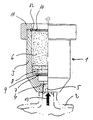
- the invention is explained in more detail using an exemplary embodiment that is shown in the drawing.
- the drawing shows one Degassing cap half in a vertical section and half in a side view.
- a degassing cap 1 is screwed onto a liquid container 2, which is only indicated by dash-dotted lines in the drawing.
- the degassing closure 1 has a substantially cylindrical closure housing 3, which has in its bottom 4 a connection opening 5 with an internal thread, which is screwed onto a connection piece of the liquid container 2.
- an adsorbent pack 6 which consists, for example, of activated carbon, a molecular sieve or diatomaceous earth and / or a neutralizing agent, the chemical behavior of which is based on the liquid contained in the liquid container 2. It is in particular a highly pure, but in most cases also aggressive and / or toxic liquid that is used, for example, in semiconductor production, for example a highly pure, highly concentrated acid or alkali.
- a bottom frit plate 7 is arranged above the bottom 4 of the closure housing 3 and is pressed sealingly against a housing seat 9 by a nut 8 screwed into the closure housing 3.
- the lower frit plate 7 consists of an inert material, preferably of polytetrafluoroethylene or perfluoroalkoxy copolymer with a pore size of preferably from 0.1 to 1 ⁇ m.
- the closure housing 3 On the top of the closure housing 3 there is an upper frit plate 10 made of the same material as the lower frit plate 7.
- the upper frit plate 10 is also sealed against one by a union nut 11 Housing seat 12 pressed.
- the adsorbent pack 6 is thus enclosed between the frit plates 7 and 10 in the closure housing 3.
- the degassing closure 1 can also be connected to the liquid container 2 via a pipeline or a hose line.
- the gases or vapors formed in the liquid container 2 enter the degassing closure 1 from below, as indicated by an arrow 13 in the drawing.
- the alleys or vapors enter the adsorbent pack 6 and are adsorbed, absorbed and / or neutralized there. At the same time it is achieved that no impermissible internal pressure can build up in the liquid container 2.
- At least the closure housing 3 and preferably also the nuts 8, 11 are made of inert material, it is effectively prevented that the liquid accommodated in the liquid container 2 can react with parts of the degassing closure.
- Fluorinated plastics such as polytetrafluoroethylene, polyvinylidene fluoride or perfluoroalkoxy copolymer are preferably used as the material for the parts of the degassing closure 1.
Landscapes
- Engineering & Computer Science (AREA)
- Mechanical Engineering (AREA)
- Degasification And Air Bubble Elimination (AREA)
- Sampling And Sample Adjustment (AREA)
- Packages (AREA)
Description
- Die Erfindung betrifft einen Entgasungsverschluß für Flüssigkeitsbehälter, mit einem mit dem Flüssigkeitsbehälter dicht verbindbaren Verschlußgehäuse, in dem eine Absorptions- oder Neutralisationsmittelpackung eingeschlossen ist.
- Derartige Entgasungsverschlüsse, auch als Entgasungsventile bezeichnet, werden auf Behälter für Flüssigkeiten aufgesetzt, die ständig Gase oder Dämpfe entwickeln. Der gasdurchlässige Entgasungsverschluß verhindert, daß sich dabei ein zu hoher Innendruck im Behälter aufbaut, wobei zugleich gewährleistet sein muß, daß die im Behälterinnenraum entstehenden Gase oder Dämpfe keine störende, belästigende oder schädliche Auswirkung auf die Umgebung haben.
- Gasdurchlässige Verschlußkappen mit Filtereinsätzen sind in unterschiedlichen Ausführungsformen bekannt (US-PS 4 420 094, 3 944 437). Hierbei werden jedoch rein mechanisch wirdende Filtereinsätze verwendet, die nicht dafür geeignet sind, gasförmige oder dampfförmige Stoffe zurückzuhalten, so daß diese in dei Umgebung austreten können.
- Ein bekannter Entgasungsverschluß der eingangs genannten Gattung ist als Geruchsverschluß ausgeführt (DE-OS 34 08 887). Dieser Geruchsverschluß enthält eine Adsorptionsmittelpackung, bespielsweise aus Aktivkohle oder einem Molekularsieb, an die sich behälterseitig ein Kunststoffsieb anschließt. Dieses Kunststoffsieb dient nur dazu, die Adsorptionsmittelpackung zu halten. Um ein Eindringen von Flüssigkeit aus dem Behälter in die Adsorptionsmittelpackung zu verhindern, ist unterhalb des Kunststoffsiebes ein gasdurchlässiger, jedoch flüssigkeitsundurchlässiger Verschluß vorgesehen, der aus einer Verschlußkugel und einem feinkapillar geriffelten Kugelsitz besteht. Die Kugel stellt ein bewegtes Teil dar, das an seinem Sitz einem Abreib erzeugen könnte. Die Abriebpartikel könnten in die im Behälter aufgenommene Flüssigkeit gelangen. Auch Partikel der Adsorptionsmittelpackung, beispielsweise der Aktivkohle, könnten durch das Kunststoffsieb hindurch in den Kugelsitz gelangen und von dort bei einer Bewegung der Verschlußkugel in den Behälterinnenraum austreten.
- Diese Verunreinigungen sind jedoch verhältnismäßig gering und können daher in vielen Fällen in Kauf genommen werden. Dies gilt jedoch nicht für hochreine Flüssigkeiten, wie sie in der Halbleiterfertigung verwendet werden. Dort müssen bereits geringste Verunreinigungen sorgfältig vermieden werden. Dashalb sind in diesen Einsatzbereichen Entgasungsventile mit bewegten Teilen und/oder mit der Möglichkeit, daß Partikel aus der Adsorptionsmittelpackung in den Behälter eintreten, ausgeschlossen.
- Ausgabe der Erfindung ist es daher, ein Entgasungsventil der eingangs genannten Gattung zu schaffen, das für den Einsatz an Behältern für hochreine Flüssigkeiten geeignet ist. Insbesondere muß jegliche Kontamination der Flüssigkeit ausgeschlossen sein; deshalb müssen bewegte, Abrieb erzeugende Teile vermieden werden. Weiter muß verhindert werden, daß Partikel des Adsorptionsmittels in die Flüssigkeit gelangen können. Schließlich muß jede Berührungsmöglichkeit der Flüssigkeit mit Teilen ausgeschlossen werden, mit denen die Flüssigkeit reagieren könnte.
- Diese Aufgabe wird erfindungsgemäß dadurch gelöst, daß die Adsorptionsmittelpackung zwischen jeweils einer unteren und einer oberen, am Verschlußgehäuse dicht abschließenden Fritteplatte aus inertem Material eingeschlossen ist und daß das Verschlußgehäuse ebenfalls aus inertem Material besteht.
- Die behälterseitig an die Adsorptionsmittelpackung anschließende Fritteplatte stellt einen gasdurchlässigen, jedoch weitgehend flüssigkeitsdichten Verschluß dar, der Jedoch keine bewegten Teile aufweist, so daß kein Abrieb entstehen kann. Deshalb besteht auch keine Gefahr, daß hochreine Flüssigkeiten, die in dem Behälter transportiert werden, durch Abrieb kontaminiert werden. Infolge der sehr geringen Porengröße stellt die Fritteplatte einen zwar gasdurchlässigen, jedoch weitestgehend flüssigkeitsdichten Verschluß dar, der die Entgasung ermöglicht, zugleich aber das Eindringen von Flüssigkeit in die Adsorptionsmittelpackung verhindert. Dadurch wird die Gefahr ausgeschlossen, daß eine direkte Berührung der Flüssigkeit mit dem Adsorptionsmittel erfolgt und Teile des Adsorptionsmittels ausgewaschen werden und als Verunreinigungen in die Flüssigkeit gelangen könnten.
- Außerdem ist die Fritteplatte auch für feinste Partikel des Adsorptionsmittels undurchlässig, so daß diese Partikel nicht in die Flüssigkeit gelangen können.
- Alle Teile, die mit der Flüssigkeit in Berührung kommen könnten, nämlich die behälterseitige Fritteplatte und das Verschlußgehäuse, bestehen aus inertem Material, so daß jegliche Reaktion mit der Flüssigkeit ausgeschlossen ist.
- Die obere, ebenso feinporige Fritteplatte verhindert einerseits das Eindringen von Verunreinigungen von außen in die Adsorptionsmittelpackung, deren Funktionsfähigkeit dadurch beeinträchtigt werden könnte, und hält andererseits die Adsorptionsmittelpackung dicht im Verschlußgehäuse, so daß auch ein feinkörniges oder pulverförmiges Adsorptionsmittel nicht austreten kann. Schließlich stellt diese obere Fritteplatte einen zusätzlichen flüssigkeitsdichten Verschluß dar, der bei extremen Beanspruchungen des Flüssigkeitsbehälters, beispielsweise bei einem unfallbedingten Sturz eine zusätzliche Sicherheit gegen das Austreten der oftmals gefährlichen und/oder giftigen Flüssigkeit bietet.
- Der erfindungsgemäße Entgasungsverschluß ist somit im Gegensatz zu allen aus dem Stand der Technik bekannten Entgasungsverschlüssen für solche Flüssigkeitsbehälter geeignet, in denen hochreine Flüssigkeiten gelagert und transportiert werden, wie sie beispielsweise in der Halbleiterfertigung verwendet werden.
- Gemäß einer weiteren Ausgestaltung des Erfindungsgedankens ist vorgesehen, daß die untere und/oder die obere Fritteplatte durch jeweils eine am Verschlußgehäuse aufgeschraubte Mutter gegen jeweils einen Gehäusesitz gedrückt wird. In kontruktiv einfacher und raumsparender Weise wird hierbei eine feste und dichte Verbindung zwischen den beiden Fritteplatten und dem Verschlußgehäuse geschaffen.
- Die Erfindung wird nachfolgend an einem Ausführungsbeispiel näher erläutert, daß in der Zeichnung dargestellt ist. Die Zeichnung zeigt einen Entgasungsverschluß zur Hälfte in einem senkrechten Schnitt und zur Hälfte in einer Seitenansicht.
- Ein Entgasungsverschluß 1 ist auf einen in der Zeichnung mit strichpunktierten Linien nur angedeuteten Flüssigkeitsbehälter 2 aufgeschraubt. Der Entgasungsverschluß 1 weist ein im wesentlichen zylindrisches Verschlußgehäuse 3 auf, das in seinem Boden 4 eine Anschlußöffnung 5 mit Innengewinde hat, das auf einen Anschlußstutzen des Flüssigkeitsbehälters 2 aufgeschraubt ist.
- Im Innerne des Verschlußgehäuses 3 befindet sich eine Adsorptionsmittelpackung 6, die beispielsweise aus Aktivkohle, aus einem Molekularsieb oder aus Kieselgur und/oder aus einem Neutralisationsmittel besteht, das in seinem chemischen Verhalten auf die Flüssigkeit abgestellt ist, die im Flüssigkeitsbehälter 2 enthalten ist. Es handelt sich dabei insbesondere um eine hochreine, in den meisten Fällen aber auch aggressive und/oder giftige Flüssigkeit, die beispielsweise in der Halbleiterfertigung verwendet wird, beispielsweise eine hochreine, hochkonzentrierte Säure oder Lauge.
- Über dem Boden 4 des Verschlußgehäuses 3 ist eine untere Fritteplatte 7 angeordnet, die durch eine in das Verschlußgehäuse 3 eingeschraubte Mutter 8 gegen einen Gehäusesitz 9 dichtend gedrückt wird. Die untere Fritteplatte 7 besteht aus inertem Material, vorzugsweise aus Polytetrafluorethylen oder Perfluoralkoxy-Copolymer mit einer Porengröße von vorzugsweise von 0,1 bis 1 µm.
- An der Oberseite des Verschlußgehäuses 3 befindet sich eine obere Fritteplatte 10 aus gleichem Material wie die untere Fritteplatte 7. Auch die obere Fritteplatte 10 wird durch eine Überwurfmutter 11 dichtend gegen einen Gehäusesitz 12 gedrückt. Die Adsorptionsmittelpackung 6 ist somit zwischen den Fritteplatten 7 und 10 im Verschlußgehäuse 3 eingeschlossen.
- Abweichend von dem dargestellten Ausführungsbeispiel kann der Entgasungsverschluß 1 auch über eine Rohrleitung oder eine Schlauchleitung mit dem Flüssigkeitsbehälter 2 verbunden sein.
- Die im Flüssigkeitsbehälter 2 entstehenden Gase oder Dämpfe treten von unten in den Entgasungsverschluß 1 ein, wie mit einem Pfeil 13 in der Zeichnung angedeutet ist. Durch die gasdurchlässige untere Fritteplatte 7 gelangen die Gasse oder Dämpfe in die Adsorptionsmittelpackung 6 und werden dort adsorbiert, absorbiert und/oder neutralisiert. Zugleich wird erreicht, daß sich in dem Flüsssigkeitsbehälter 2 kein unzulässiger Innendruck aufbauen kann.
- Da außer den Fritteplatten 7, 10 mindestens auch das Verschlußgehäuse 3 und vorzugsweise auch die Muttern 8, 11 aus inertem Material bestehen, wird wirkungsvoll verhindert, daß die im Flüssigkeitsbehälter 2 aufgenommene Flüssigkeit mit Teilen des Entgasungsverschlusses reagieren kann. Als Material für die Teile des Entgasungsverschlusses 1 werden vorzugsweise fluorierte Kunststoffe wie Polytetrafluorethylen, Polyvinylidenfluorid oder Perfluoralkoxy-Copolymer verwendet.
Claims (2)
- Entgasungsverschluß (1) für Flüssigkeitsbehälter (2), mit einem mit dem Flüssigkeitsbehälter dicht verbindbaren Verschlußgehäuse (3), in dem eine Adsorptions- oder Neutralisationsmittelpackung (6) eingeschlossen ist, dadurch gekennzeichnet, daß die Adsorptionsmittelpackung (6) zwischen einer unteren und einer oberen, am Verschlußgehäuse (3) dicht abschließenden Fritteplatte (7, 10) aus inertem Material eingeschlossen ist und daß das Verschlußgehäuse (3) ebenfalls aus inertem Material besteht.
- Entgasungsverschluß nach Anspruch 1, dadurch gekennzeichnet, daß die untere und/oder die obere Fritteplatte (7, 10) durch jeweils eine am Verschlußgehäuse (3) aufgeschraubte Mutter (8 bzw. 11) gegen jeweils einem Gehäusesitz (9 bzw. 12) gedrückt wird.
Applications Claiming Priority (2)
| Application Number | Priority Date | Filing Date | Title |
|---|---|---|---|
| DE19873720939 DE3720939A1 (de) | 1987-06-25 | 1987-06-25 | Entgasungsverschluss fuer fluessigkeitsbehaelter |
| DE3720939 | 1987-06-25 |
Publications (3)
| Publication Number | Publication Date |
|---|---|
| EP0296437A2 EP0296437A2 (de) | 1988-12-28 |
| EP0296437A3 EP0296437A3 (en) | 1989-03-15 |
| EP0296437B1 true EP0296437B1 (de) | 1991-11-27 |
Family
ID=6330236
Family Applications (1)
| Application Number | Title | Priority Date | Filing Date |
|---|---|---|---|
| EP88109343A Expired - Lifetime EP0296437B1 (de) | 1987-06-25 | 1988-06-11 | Entgasungsverschluss für Flüssigkeitsbehälter |
Country Status (2)
| Country | Link |
|---|---|
| EP (1) | EP0296437B1 (de) |
| DE (2) | DE3720939A1 (de) |
Families Citing this family (6)
| Publication number | Priority date | Publication date | Assignee | Title |
|---|---|---|---|---|
| FR2646100B1 (fr) * | 1989-04-25 | 1991-08-16 | Sogea | Dispositif pour l'epuration des gaz echanges entre l'interieur d'un caveau et l'exterieur |
| DE9107432U1 (de) * | 1991-06-17 | 1991-08-22 | Frohn, Eric, 8000 München | Entgasungsventil |
| DE59202439D1 (de) * | 1991-06-17 | 1995-07-13 | Eric Dr Frohn | Entgasungventil eines Behälters für den Transport gefährlicher Flüssigkeiten. |
| AU3472393A (en) * | 1992-07-14 | 1994-01-31 | Ecolab Inc. | Activated carbon closure vent |
| IT1265433B1 (it) * | 1993-12-23 | 1996-11-22 | Luigi Goglio | Valvola di degasazione per prodotti aromatici, in particolare caffe' |
| DE29511683U1 (de) * | 1995-07-19 | 1995-09-28 | W.L. Gore & Associates Gmbh, 85640 Putzbrunn | Verschlußkappe für Behälter, Gehäuse, Flaschen o.dgl |
Family Cites Families (8)
| Publication number | Priority date | Publication date | Assignee | Title |
|---|---|---|---|---|
| GB507941A (en) * | 1938-02-07 | 1939-06-23 | Automotive Prod Co Ltd | Improvements in or relating to vented closure devices for liquid containers |
| DE949389C (de) * | 1954-08-08 | 1956-09-20 | Fritz Roth K G | Verschlussdeckel fuer Fluessigkeitsbehaelter, insbesondere Brennstoffbehaelter von Kraftfahrzeugen |
| GB1395744A (en) * | 1972-05-22 | 1975-05-29 | Automotive Proeucts Ltd | Oil filler cap |
| DE7506673U (de) * | 1975-03-04 | 1975-07-24 | Elbatainer Kunststoff | Druckausgleichs-Schraubkappe |
| US3961724A (en) * | 1975-03-13 | 1976-06-08 | Briggs & Stratton Corporation | Fuel tank filler cap with improved vent |
| DE3039528A1 (de) * | 1980-10-20 | 1982-06-03 | Degussa Ag, 6000 Frankfurt | Sicherheitsvorrichtung fuer emballagen, welche wasserstoff abgebende pyrophore metallkatalysatoren enthalten |
| DE8233621U1 (de) * | 1982-11-30 | 1983-02-03 | Rhein-Conti Kunststofftechnik GmbH, 6800 Mannheim | Gasdurchlaessiger Gefaessverschluss |
| DE3408887A1 (de) * | 1984-03-10 | 1985-09-12 | Henkel KGaA, 4000 Düsseldorf | Geruchsverschluss |
-
1987
- 1987-06-25 DE DE19873720939 patent/DE3720939A1/de not_active Withdrawn
-
1988
- 1988-06-11 DE DE8888109343T patent/DE3866438D1/de not_active Expired - Fee Related
- 1988-06-11 EP EP88109343A patent/EP0296437B1/de not_active Expired - Lifetime
Also Published As
| Publication number | Publication date |
|---|---|
| EP0296437A2 (de) | 1988-12-28 |
| DE3720939A1 (de) | 1989-01-05 |
| DE3866438D1 (de) | 1992-01-09 |
| EP0296437A3 (en) | 1989-03-15 |
Similar Documents
| Publication | Publication Date | Title |
|---|---|---|
| DE69313809T2 (de) | Behälter für Substanzen konzentriert in Form von Pulver oder einer Flüssigkeit zum Auflösen in einem Behältnis zum Zeitpunkt der Nutzung | |
| DE69300280T2 (de) | Versorgungseinrichtung für ein hochreines Fluid. | |
| DE69609287T2 (de) | Fahrzeug-Betankungsventil | |
| DE69513174T2 (de) | System zur abgabe und rezirkulierung von chemischen flüssigkeiten | |
| DE68905752T2 (de) | Zum Ändern der Zusammensetzung einer Flüssigkeit bestimmte Verpackung. | |
| DE69101084T2 (de) | Reinigungsvorrichtung für eine Flüssigkeit mit einer im Deckelkörper eines Behälters integrierten Luftpumpe. | |
| DE3806998C2 (de) | Steuereinheit für unter Druck stehende Gase | |
| EP0550503B1 (de) | Einweg-druckbehälter, insbesondere als nachfüllbehälter für kälte- und klimaanlagen | |
| EP0077556A2 (de) | Konzentratbehälter | |
| CH693630A5 (de) | Aufnahmevorrichtung. | |
| EP0754630B1 (de) | Verschlusskappe für Behälter, Gehäuse, Flaschen oder dergleichen | |
| EP0417554A1 (de) | Behälter mit Schraubverschlusskappe | |
| DE7826217U1 (de) | Behaelterverschluss | |
| DE69027699T2 (de) | Vorrichtung zur Trennung von Gas aus Flüssigkeiten und zur Entladung des ausgeschiedenen Gases | |
| WO2004067400A1 (de) | Einwegventileinrichtung | |
| EP0296437A2 (de) | Entgasungsverschluss für Flüssigkeitsbehälter | |
| DE19814958C2 (de) | Kraftfahrzeugtank aus Kunststoff | |
| EP0548570B1 (de) | Befüll- und Entleerungsvorrichtung | |
| DE10042640A1 (de) | Verschluß für einen Füllstutzen mit Dichtung | |
| DE3819689A1 (de) | Absperrventil | |
| EP0206018A1 (de) | Ventil für Chemikalienbehälter | |
| EP0650446A1 (de) | Schraubdeckel. | |
| DE3825575C2 (de) | ||
| EP0008662A1 (de) | Vorrichtung zum Füllen und Entleeren von Füllgutbehältern mit gasförmigen und/oder flüssigen Stoffen und Anwendung für eine Pumpe und/oder Dosiereinrichtung | |
| EP0110046A1 (de) | Gasdurchlässiger Gefässverschluss |
Legal Events
| Date | Code | Title | Description |
|---|---|---|---|
| PUAI | Public reference made under article 153(3) epc to a published international application that has entered the european phase |
Free format text: ORIGINAL CODE: 0009012 |
|
| AK | Designated contracting states |
Kind code of ref document: A2 Designated state(s): DE FR GB IT NL |
|
| PUAL | Search report despatched |
Free format text: ORIGINAL CODE: 0009013 |
|
| AK | Designated contracting states |
Kind code of ref document: A3 Designated state(s): DE FR GB IT NL |
|
| 17P | Request for examination filed |
Effective date: 19890718 |
|
| 17Q | First examination report despatched |
Effective date: 19910503 |
|
| GRAA | (expected) grant |
Free format text: ORIGINAL CODE: 0009210 |
|
| AK | Designated contracting states |
Kind code of ref document: B1 Designated state(s): DE FR GB IT NL |
|
| ITF | It: translation for a ep patent filed | ||
| GBT | Gb: translation of ep patent filed (gb section 77(6)(a)/1977) | ||
| REF | Corresponds to: |
Ref document number: 3866438 Country of ref document: DE Date of ref document: 19920109 |
|
| ET | Fr: translation filed | ||
| PLBE | No opposition filed within time limit |
Free format text: ORIGINAL CODE: 0009261 |
|
| STAA | Information on the status of an ep patent application or granted ep patent |
Free format text: STATUS: NO OPPOSITION FILED WITHIN TIME LIMIT |
|
| 26N | No opposition filed | ||
| PGFP | Annual fee paid to national office [announced via postgrant information from national office to epo] |
Ref country code: GB Payment date: 19930528 Year of fee payment: 6 |
|
| PGFP | Annual fee paid to national office [announced via postgrant information from national office to epo] |
Ref country code: FR Payment date: 19930609 Year of fee payment: 6 |
|
| PGFP | Annual fee paid to national office [announced via postgrant information from national office to epo] |
Ref country code: DE Payment date: 19930623 Year of fee payment: 6 |
|
| PGFP | Annual fee paid to national office [announced via postgrant information from national office to epo] |
Ref country code: NL Payment date: 19930630 Year of fee payment: 6 |
|
| PG25 | Lapsed in a contracting state [announced via postgrant information from national office to epo] |
Ref country code: GB Effective date: 19940611 |
|
| PG25 | Lapsed in a contracting state [announced via postgrant information from national office to epo] |
Ref country code: NL Effective date: 19950101 |
|
| GBPC | Gb: european patent ceased through non-payment of renewal fee |
Effective date: 19940611 |
|
| NLV4 | Nl: lapsed or anulled due to non-payment of the annual fee | ||
| PG25 | Lapsed in a contracting state [announced via postgrant information from national office to epo] |
Ref country code: FR Effective date: 19950228 |
|
| PG25 | Lapsed in a contracting state [announced via postgrant information from national office to epo] |
Ref country code: DE Effective date: 19950301 |
|
| REG | Reference to a national code |
Ref country code: FR Ref legal event code: ST |
|
| PG25 | Lapsed in a contracting state [announced via postgrant information from national office to epo] |
Ref country code: IT Free format text: LAPSE BECAUSE OF NON-PAYMENT OF DUE FEES;WARNING: LAPSES OF ITALIAN PATENTS WITH EFFECTIVE DATE BEFORE 2007 MAY HAVE OCCURRED AT ANY TIME BEFORE 2007. THE CORRECT EFFECTIVE DATE MAY BE DIFFERENT FROM THE ONE RECORDED. Effective date: 20050611 |