EP0296337B1 - Cylindre profilé de fermeture - Google Patents
Cylindre profilé de fermeture Download PDFInfo
- Publication number
- EP0296337B1 EP0296337B1 EP88106976A EP88106976A EP0296337B1 EP 0296337 B1 EP0296337 B1 EP 0296337B1 EP 88106976 A EP88106976 A EP 88106976A EP 88106976 A EP88106976 A EP 88106976A EP 0296337 B1 EP0296337 B1 EP 0296337B1
- Authority
- EP
- European Patent Office
- Prior art keywords
- key
- cylinder
- cylinder core
- housing part
- core
- Prior art date
- Legal status (The legal status is an assumption and is not a legal conclusion. Google has not performed a legal analysis and makes no representation as to the accuracy of the status listed.)
- Expired - Lifetime
Links
Images
Classifications
-
- E—FIXED CONSTRUCTIONS
- E05—LOCKS; KEYS; WINDOW OR DOOR FITTINGS; SAFES
- E05B—LOCKS; ACCESSORIES THEREFOR; HANDCUFFS
- E05B27/00—Cylinder locks or other locks with tumbler pins or balls that are set by pushing the key in
Definitions
- the invention relates to a profile lock cylinder with a cylinder housing, the first housing part containing a first axial bore and a cylinder core axially immovably mounted therein as well as spring-loaded tumbler elements, and a connecting bar thus leaving a recess for the lock bit rotatable by the cylinder core integrally connected second housing part with a second axial bore located therein, coaxial to the first axial bore, the cylinder core containing a longitudinal key channel for receiving a key provided with incisions and further tumbler elements, which together with the tumbler elements accommodated in the first housing part into a rotational mobility of the cylinder core enabling release position are to be moved.
- Profile lock cylinders of this type are generally known for security locks, in both so-called half-cylinder and double-cylinder shapes.
- the second housing part is axially very short and its correspondingly short axial bore only serves to better support the locking bar, while in the double cylinder the second housing part is used to accommodate a further cylinder core and is designed in accordance with the former housing part.
- the axial bores in the two housing parts run coaxially with one another and are continuously smooth-walled, just like the cylinder cores stored therein.
- the associated key has such incisions that the tumbler elements, which usually consist of housing pins and core pins, are shifted against the spring load with the help of this key to such an extent that the separation points between each housing pin and a core pin match the interface between the cylinder core and the cylinder housing. Then the cylinder core can be turned with the key and the lock bit located on the core actuates the associated lock either in the opening or closing direction.
- the tumbler elements which usually consist of housing pins and core pins
- One method of forcibly opening the lock without an associated key is to pull out the cylinder core by force, thereby creating access to the lock bit and thus opening the lock.
- This violent pulling out takes place, for example, by means of a corkscrew-like cutting element, for example a screw, which is screwed into the key channel and is thus firmly anchored to the cylinder core in such a way that it can be pulled out of the cylinder housing.
- the locking tumbler pins are sheared off.
- This can also be an axial fixation of the rotatable one Do not prevent the circlip serving as the cylinder core in the cylinder housing.
- the invention is therefore based on the object of improving a profile lock cylinder of the type mentioned at the outset so that a forceful pulling out of the cylinder core from the cylinder housing part is not possible.
- an inseparably attached ring projection is provided on the cylinder core on the lockable side and engages axially behind the first housing part and the second axial bore in the second housing part has a diameter which is at least as large as the outside diameter of this ring projection, so that the cylinder core can be inserted through this axial bore into the bore of the first housing part.
- the cylinder core is secured against being pulled out by an annular projection provided on it on the closable side.
- the ring projection on the cylinder core can be made solid in the desired manner. Since the cylinder core with the associated cylinder housing part is assembled from the lockable side, the ring projection can therefore be designed with the safety conditions in mind, regardless of the installation process.
- the ring projection can also consist of hard metal, for example.
- the ridge projection is in one piece with the cylinder core, it being understood that that it can also consist of the same material as the cylinder core. If the cylinder core is produced by injection molding, the ring projection can be produced in the same production process, so that the production outlay is practically negligible.
- an annular projection that partially overlaps the cylinder core on the front side can also be present on the first housing part on the key insertion side.
- This can be closed all around and the key channel on the back of the key can be filled by a web, the height of which is equal to the height of this ring projection.
- the all-round closed design of this ring projection ensures additional pull-out resistance and requires a key channel closed on the back of the key, for which purpose a web in the cylinder core is used, with which the housing pins are held down when the cylinder core is rotated.
- the web is in one piece with the cylinder core and pin bore sections located in the web are completely filled.
- the ring projection on the first cylinder housing part can be slit key width at least in front of the section of the key channel receiving the key back and the key can have a slot receiving this ring projection when the cylinder core rotates.
- the key channel can have a conventional size and in particular be open at the top, so that the back of the key serves to hold down the housing pins when the cylinder core is rotated.
- the cylinder core for forming the ring projection can have a conical outer circumference tapering on the key insert side at least on one longitudinal section, and the first axial bore located in the first housing part can be correspondingly conical.
- the taper or the inclination of the outer circumference of the core need only be slight, for example 0.5 degrees. This is sufficient for the cylinder housing to be able to offer sufficient resistance to the removal of the cylinder core with the usual violent means. In any case, the violent means used to destroy common tumbler pins or circlips do not lead to the goal.
- the cylinder housing and cylinder core are sufficiently solid to be able to provide the required resistance.
- both can be given the required shape in simple operations. If the cylinder core and the cylinder housing form a cylindrical key straight guide section in the initial region of the key channel, appropriate production must take place for the conical surface which is only partially present over the length of the cylinder core and the associated cylinder housing part, but the key straight guide section can ensure the horizontal arrangement of the key shaft in the cylinder core.
- the movable tumbler elements are crowned in the area of the parting plane formed by the cylinder core and the cylinder housing part to a degree that compensates for the height difference formed by the taper between the beginning and end of the cone.
- the crowning of the movable tumbler elements ensures that the latter, in particular the pins of spring-loaded pin tumblers, regardless of the taper in the same dimensions and in the proven Construction can also be used with lock cylinders with a conical cylinder core, as with conventional lock cylinders. Existing tolerances are also irrelevant. Rather, the different levels of the parting plane due to the taper are all in the region of the crown of the moving tumblers.
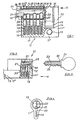
- the locking cylinder 10 shown in Fig. 1 is a half cylinder approximately of the profile of Fig. 4.
- the locking cylinder 10 has a cylinder housing 11, which consists of a first housing part 11 'and a second housing part 11', which are connected to each other via the connecting web 11 ' are.
- a first axial bore 27 and an axially immovably mounted cylinder core 12 are contained therein.
- the connecting web 11 ′′′ there is a threaded bore 13 for the engagement of a fastening screw with which the locking cylinder 10 is fixed in a lock housing.
- the bearing of the locking bar 15 serves on both sides of the locking bar 15 existing bearing rings 16, and also the second axial bore 33 in the leg 32 of the second housing part 11 ⁇ .
- the storage of the locking bar 15, its design and its assembly with the cylinder core 12 are conventional and are therefore not shown in detail.
- the cylinder housing part 11 has a plurality of side by side in a row arranged pin holes 17, each receiving a spring 18 which is supported at one end on the bore bottom 19 and the other end on a housing pin 20.
- the housing pin 20 transmits the force of the spring 18 to a core pin 21, which projects into a key channel 22 of the cylinder core 12.
- the key channel 22 receives the key shaft 23 of the key 24, so that its key incisions 25 reach the core pins 21 in a predetermined position. Since the core pins 21 are of different lengths and the depth of the key incisions 25 is specifically matched to the different length of the core pins 21, these are held at different heights by the key shaft 23 or by the key incisions 25 on the key side in the manner shown in FIG. 1, however so that the core pins 21 on the housing pin side Project axially equally far and, in particular, complete with the outer circumference of the cylinder core 12.
- the core pin-side ends 26 of the housing pins 20 also terminate with the inner circumference of the bore 27 of the cylinder housing 11 which rotatably supports the cylinder core 12, so that the cylinder core 12 can be rotated using the key 24, which due to its rotationally fixed connection to the lock bit 15 increases whose rotation and thus leads to a lock actuation.
- the key 24 can be inserted exactly into the position shown in FIG. 1 in the key channel 22, the key 24 has an insertion stop 28 and the cross section of the key 24 has key notches 29, so that only one key 24 with one through the notches 29 conditional shaft profile can be inserted into the key channel 22.
- the profile of the key channel 22 is, for example, similar to that of the channel 22 in FIG. 4.
- the cylinder housing part 11 On the key insertion side, the cylinder housing part 11 'has an annular projection 30 which forms an abutment for the insertion stop 28 of the key 24 and also prevents the cylinder core 12 from being pulled out violently against the direction of insertion of the key 24.
- the ring projection 30 thus reduces the diameter of the bore 27 of the cylinder housing 11.
- the cylinder core 12 must be installed in this bore 27 on the lockable side, that is to say in FIG. 1 from right to left through the axial bore 33 present in the second, axially short housing part 11 through it.
- the back 35 of the key 24 is not quite as high as in the case of a key of a locking cylinder without a ring projection.
- the key channel 22 is not completely through the Key back 35 filled, which consequently can not ensure that the housing pins 20 are held down by the key 24 at its corresponding rotational position.
- the key channel 22 is filled on the key back side by a web 34 which guides the key shaft 23 on the key back 35.
- the web 34 serves to hold down the housing pins 20 when the key 24 is in a corresponding rotational position.
- the web 34 is produced in one piece with the cylinder core 12.
- the ring projection 31 on the closable side thereof with which the cylinder core engages in a corresponding, not specified annular groove of the cylinder housing part 11 ', so that it assumes the desired position in which its core pins 21 align with the housing pins 20.
- this annular projection 31 cannot be reached by unauthorized persons and therefore cannot be drilled out from the outside.
- the axial bore 33 in the second housing part 11 'or in the leg 32 has a diameter which is at least equal to the outer diameter of the ring projection 31 in order to be able to insert the cylinder core 12 with the ring projection 31.
- Such a dimensioned bore 33 is unproblematic in the profile half cylinder shown in FIG. 1.
- the second cylinder core to be installed must also have a correspondingly larger diameter.
- the pin bores 17 are only partially occupied by a spring 18, a housing pin 20 and a core pin 21. They are made by, for example is drilled in direction b through the cylinder housing part 11 'and the cylinder core 12.
- the resulting bore sections 36 in the cylinder housing part 11 'and 37 in the cylinder core 12 above the key spine 35 must be closed so that the core pins 21 when rotating the core 12 not in open bore sections 36 of the cylinder housing 11 or so that the housing pins 20 not in open bore sections 37 of the cylinder core 12 and prevent its further turning. This filling of the relevant bore sections 36, 37 takes place, for example, by soldering.
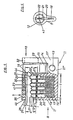
- the half cylinder shown in FIGS. 2 to 4 consists essentially of the same components as the half cylinder of FIG. 1.
- the ring projection 30 on the key insertion side has a slot 38, so that the key back 23 has a customary height and can be inserted unhindered into the key channel 22 by the ring projection 30.
- the key 24 is provided with a slot 39, the depth and width of which are matched to the height and width of the ring projection 30.
- the profile lock cylinder 10 shown in FIGS. 5 and 6 largely coincides with the profile lock cylinder described above.
- the corresponding components are all given the same names and reference numerals.
- the cylinder core 12 is conical here to form the axially securing ring projection, namely over its length section 1.
- the conicity given on this length section 1 is determined by the difference between the rear, largest diameter h and the front, smallest Diameter d of the cylinder core 12 in a straight line of the surface lines over the entire conical outer circumference 41 of the cylinder core 12.
- the taper is only slight, for example the surface lines have an inclination of approximately 0.5 degrees relative to the horizontal or against the cylinder core axis 43. This slight inclination is sufficient so that the cylinder core 12 is not forced axially, to the left in FIG. 5, can be pulled out of the cylinder housing part 11 '.
- the key 24 is usually held in the key channel 22 in such a way that it maintains the position shown in FIG. However, it is also possible that the key 24 does not maintain this position or does not maintain it to the desired extent, that is to say under the pressure of the tumbler springs 18 or as a result of slanted insertion upwards into the free area 44 of the key channel 22 between the key back 35 and the cylinder housing 11. This is possible in the case of larger key tolerances, or if the key does not have enough or no longitudinal notches 29. In contrast to the illustration in FIG. 5, such designs are also suitable, for example, in the case of locking cylinders provided with magnetic locks.
- the key straight guide section 40 shown in FIG. 5 which is formed over the length s of the cylinder housing part 11 'and the cylinder core 12 by both in the area of the key channel 22.
- This key straight guide section 40 requires a cylindrical section of the cylinder core 12 which extends over the length s. Such a comparatively short length section of the cylinder core 12 is sufficient to hold the key shaft 23 to keep it sufficiently straight or horizontal.
- the key channel 22 could just as well be at least partially closed on the back, for example by a pin crossing the channel 22 outside the actual key guide, on which the key, which is entering at an incline, slides with its beveled key tip and thereby reaches and is held in its axially parallel position .
- FIG. 5 Another measure is to form the housing pins 20 and core pins 21 shown in FIG. 5 on their mutually facing support surfaces in the manner shown.
- the crowning is dimensioned such that the height differences formed by the taper or the difference between h and d between the beginning and end of the cone are irrelevant when closing, because the separating surface sections of the cylinder core 12, which are somewhat offset in height, meet crowned and consequently evasive pin ends, so that the key 24 and thus the cylinder core 12 can be rotated.
- the tumbler pins 20, 21 then have exactly the position shown in FIG. 5 in the region of the bore 27 or the parting plane.
- the taper of the cylinder core 12 has the prerequisite that the cylinder core 12 here from the lockable side, ie through the existing in the second housing half 11 ⁇ or in the housing leg 32 through hole 33, must be installed in the bore 27 of the cylinder housing part 11 ' .
- the bore 33 on the inside of the door, even in the case of a profile double cylinder housing, is thus somewhat larger than the largest diameter h at the end of the cone, in order to be able to insert the cylinder core 12.
Landscapes
- Lock And Its Accessories (AREA)
Claims (7)
Priority Applications (1)
| Application Number | Priority Date | Filing Date | Title |
|---|---|---|---|
| AT88106976T ATE64170T1 (de) | 1987-05-07 | 1988-04-30 | Profilschliesszylinder. |
Applications Claiming Priority (4)
| Application Number | Priority Date | Filing Date | Title |
|---|---|---|---|
| DE8706551U DE8706551U1 (fr) | 1987-05-07 | 1987-05-07 | |
| DE8706551U | 1987-05-07 | ||
| DE8708506U | 1987-06-19 | ||
| DE8708506U DE8708506U1 (fr) | 1987-06-19 | 1987-06-19 |
Related Child Applications (2)
| Application Number | Title | Priority Date | Filing Date |
|---|---|---|---|
| EP90114305A Division-Into EP0410437B1 (fr) | 1987-05-07 | 1988-04-30 | Cylindre profilé pour fermeture |
| EP90114305A Division EP0410437B1 (fr) | 1987-05-07 | 1988-04-30 | Cylindre profilé pour fermeture |
Publications (2)
| Publication Number | Publication Date |
|---|---|
| EP0296337A1 EP0296337A1 (fr) | 1988-12-28 |
| EP0296337B1 true EP0296337B1 (fr) | 1991-06-05 |
Family
ID=25951741
Family Applications (2)
| Application Number | Title | Priority Date | Filing Date |
|---|---|---|---|
| EP90114305A Expired - Lifetime EP0410437B1 (fr) | 1987-05-07 | 1988-04-30 | Cylindre profilé pour fermeture |
| EP88106976A Expired - Lifetime EP0296337B1 (fr) | 1987-05-07 | 1988-04-30 | Cylindre profilé de fermeture |
Family Applications Before (1)
| Application Number | Title | Priority Date | Filing Date |
|---|---|---|---|
| EP90114305A Expired - Lifetime EP0410437B1 (fr) | 1987-05-07 | 1988-04-30 | Cylindre profilé pour fermeture |
Country Status (2)
| Country | Link |
|---|---|
| EP (2) | EP0410437B1 (fr) |
| DE (2) | DE3863132D1 (fr) |
Families Citing this family (2)
| Publication number | Priority date | Publication date | Assignee | Title |
|---|---|---|---|---|
| DE4109968C2 (de) * | 1991-03-22 | 2001-11-15 | Lehmann Gmbh & Co Kg Martin | Stiftzylinder für Möbelschlösser |
| WO2004111369A1 (fr) | 2003-06-16 | 2004-12-23 | Camware Holdings Pty Ltd | Serrure rotative et cle |
Family Cites Families (5)
| Publication number | Priority date | Publication date | Assignee | Title |
|---|---|---|---|---|
| FR2219682A6 (fr) * | 1973-02-28 | 1974-09-20 | Neiman Exploitation Brevets | |
| AT337036B (de) * | 1975-07-28 | 1977-06-10 | Grundmann Rohrbacher Schlosser | Schloss |
| AT355948B (de) * | 1978-11-09 | 1980-03-25 | Evva Werke | Schliessanlage, insbesondere fuer doppel- zylinderschloesser |
| CH650054A5 (de) * | 1980-11-26 | 1985-06-28 | Berchtold Ag | Notschluesseleinrichtung an einem doppelzylinderschloss. |
| DE3502860A1 (de) * | 1984-03-26 | 1985-10-03 | Lothar Laflör GmbH & Co, 5620 Velbert | Schliess-profilzylinder, insbesondere fuer feuerhemmende tueren |
-
1988
- 1988-04-30 DE DE8888106976T patent/DE3863132D1/de not_active Expired - Lifetime
- 1988-04-30 DE DE90114305T patent/DE3885109D1/de not_active Expired - Fee Related
- 1988-04-30 EP EP90114305A patent/EP0410437B1/fr not_active Expired - Lifetime
- 1988-04-30 EP EP88106976A patent/EP0296337B1/fr not_active Expired - Lifetime
Also Published As
| Publication number | Publication date |
|---|---|
| DE3863132D1 (de) | 1991-07-11 |
| EP0296337A1 (fr) | 1988-12-28 |
| DE3885109D1 (de) | 1993-11-25 |
| EP0410437B1 (fr) | 1993-10-20 |
| EP0410437A1 (fr) | 1991-01-30 |
Similar Documents
| Publication | Publication Date | Title |
|---|---|---|
| EP2868850B1 (fr) | Cadenas | |
| DE2544692B2 (de) | Zylinderschloß | |
| DE3225952A1 (de) | Schliesszylinder-flachschluessel | |
| EP0364660A2 (fr) | Serrure cylindrique | |
| EP1251223B1 (fr) | Clefs d'une système de clef passe-partout | |
| DE10220078B3 (de) | Schließzylinder | |
| EP0712980B1 (fr) | Serrure cylindrique avec noyau cylindrique et boítier cylindrique | |
| EP0296337B1 (fr) | Cylindre profilé de fermeture | |
| EP0574752B1 (fr) | Clé et cylindre de serrure correspondant notamment cyclindre de serrure profilé | |
| DE3010115A1 (de) | Arretierungsvorrichtung fuer vorreiberverschluesse, stangenverschluesse u.dgl. | |
| EP1470307B1 (fr) | Cylindre de fermeture | |
| EP0835975B1 (fr) | Serrure cylindrique | |
| DE4037358C2 (de) | Zylinderschloß | |
| DE2923598A1 (de) | Schliesszylinder und schliessanlage | |
| DE102005009153A1 (de) | Profilzylinder | |
| DE3814740A1 (de) | Profilschliesszylinder | |
| EP0861955B1 (fr) | Bouton de fenêtre verrouiable | |
| DE3844676C2 (en) | Profiled lock cylinder assembly | |
| EP3428371A1 (fr) | Barillet de serrure, cylindre de serrure, clé, dispositif de fermeture, serrure à cylindre et procédé correspondant | |
| DE2613772C2 (de) | Schließzylinder | |
| EP3228787A1 (fr) | Barillet amélioré | |
| DE60209547T2 (de) | Verriegelungsvorrichtungs-sicherheitsschloss | |
| DE4230591A1 (de) | Codierbares Zylinderschloß | |
| WO2005035921A1 (fr) | Cadenas | |
| DE384315C (fr) |
Legal Events
| Date | Code | Title | Description |
|---|---|---|---|
| PUAI | Public reference made under article 153(3) epc to a published international application that has entered the european phase |
Free format text: ORIGINAL CODE: 0009012 |
|
| AK | Designated contracting states |
Kind code of ref document: A1 Designated state(s): AT BE CH DE FR GB IT LI LU NL |
|
| 17P | Request for examination filed |
Effective date: 19890120 |
|
| 17Q | First examination report despatched |
Effective date: 19900327 |
|
| GRAA | (expected) grant |
Free format text: ORIGINAL CODE: 0009210 |
|
| AK | Designated contracting states |
Kind code of ref document: B1 Designated state(s): AT BE CH DE FR GB IT LI LU NL |
|
| REF | Corresponds to: |
Ref document number: 64170 Country of ref document: AT Date of ref document: 19910615 Kind code of ref document: T |
|
| REF | Corresponds to: |
Ref document number: 3863132 Country of ref document: DE Date of ref document: 19910711 |
|
| GBT | Gb: translation of ep patent filed (gb section 77(6)(a)/1977) | ||
| ET | Fr: translation filed | ||
| ITF | It: translation for a ep patent filed |
Owner name: STUDIO TORTA SOCIETA' SEMPLICE |
|
| PLBE | No opposition filed within time limit |
Free format text: ORIGINAL CODE: 0009261 |
|
| STAA | Information on the status of an ep patent application or granted ep patent |
Free format text: STATUS: NO OPPOSITION FILED WITHIN TIME LIMIT |
|
| 26N | No opposition filed | ||
| EPTA | Lu: last paid annual fee | ||
| PGFP | Annual fee paid to national office [announced via postgrant information from national office to epo] |
Ref country code: LU Payment date: 19950401 Year of fee payment: 8 |
|
| PG25 | Lapsed in a contracting state [announced via postgrant information from national office to epo] |
Ref country code: LU Free format text: LAPSE BECAUSE OF NON-PAYMENT OF DUE FEES Effective date: 19960430 |
|
| PGFP | Annual fee paid to national office [announced via postgrant information from national office to epo] |
Ref country code: GB Payment date: 19990315 Year of fee payment: 12 |
|
| PGFP | Annual fee paid to national office [announced via postgrant information from national office to epo] |
Ref country code: FR Payment date: 19990324 Year of fee payment: 12 Ref country code: AT Payment date: 19990324 Year of fee payment: 12 |
|
| PGFP | Annual fee paid to national office [announced via postgrant information from national office to epo] |
Ref country code: DE Payment date: 19990325 Year of fee payment: 12 |
|
| PGFP | Annual fee paid to national office [announced via postgrant information from national office to epo] |
Ref country code: CH Payment date: 19990326 Year of fee payment: 12 |
|
| PGFP | Annual fee paid to national office [announced via postgrant information from national office to epo] |
Ref country code: NL Payment date: 19990329 Year of fee payment: 12 |
|
| PGFP | Annual fee paid to national office [announced via postgrant information from national office to epo] |
Ref country code: BE Payment date: 19990414 Year of fee payment: 12 |
|
| PG25 | Lapsed in a contracting state [announced via postgrant information from national office to epo] |
Ref country code: LI Free format text: LAPSE BECAUSE OF NON-PAYMENT OF DUE FEES Effective date: 20000430 Ref country code: GB Free format text: LAPSE BECAUSE OF NON-PAYMENT OF DUE FEES Effective date: 20000430 Ref country code: CH Free format text: LAPSE BECAUSE OF NON-PAYMENT OF DUE FEES Effective date: 20000430 Ref country code: BE Free format text: LAPSE BECAUSE OF NON-PAYMENT OF DUE FEES Effective date: 20000430 Ref country code: AT Free format text: LAPSE BECAUSE OF NON-PAYMENT OF DUE FEES Effective date: 20000430 |
|
| BERE | Be: lapsed |
Owner name: NIEMANN HANS-DIETER Effective date: 20000430 |
|
| PG25 | Lapsed in a contracting state [announced via postgrant information from national office to epo] |
Ref country code: NL Free format text: LAPSE BECAUSE OF NON-PAYMENT OF DUE FEES Effective date: 20001101 |
|
| REG | Reference to a national code |
Ref country code: CH Ref legal event code: PL |
|
| GBPC | Gb: european patent ceased through non-payment of renewal fee |
Effective date: 20000430 |
|
| PG25 | Lapsed in a contracting state [announced via postgrant information from national office to epo] |
Ref country code: FR Free format text: LAPSE BECAUSE OF NON-PAYMENT OF DUE FEES Effective date: 20001229 |
|
| NLV4 | Nl: lapsed or anulled due to non-payment of the annual fee |
Effective date: 20001101 |
|
| PG25 | Lapsed in a contracting state [announced via postgrant information from national office to epo] |
Ref country code: DE Free format text: LAPSE BECAUSE OF NON-PAYMENT OF DUE FEES Effective date: 20010201 |
|
| REG | Reference to a national code |
Ref country code: FR Ref legal event code: ST |
|
| PG25 | Lapsed in a contracting state [announced via postgrant information from national office to epo] |
Ref country code: IT Free format text: LAPSE BECAUSE OF NON-PAYMENT OF DUE FEES;WARNING: LAPSES OF ITALIAN PATENTS WITH EFFECTIVE DATE BEFORE 2007 MAY HAVE OCCURRED AT ANY TIME BEFORE 2007. THE CORRECT EFFECTIVE DATE MAY BE DIFFERENT FROM THE ONE RECORDED. Effective date: 20050430 |