EP0294656A2 - Puits pour décharge de déchets - Google Patents
Puits pour décharge de déchets Download PDFInfo
- Publication number
- EP0294656A2 EP0294656A2 EP88108401A EP88108401A EP0294656A2 EP 0294656 A2 EP0294656 A2 EP 0294656A2 EP 88108401 A EP88108401 A EP 88108401A EP 88108401 A EP88108401 A EP 88108401A EP 0294656 A2 EP0294656 A2 EP 0294656A2
- Authority
- EP
- European Patent Office
- Prior art keywords
- dome
- dome according
- filter layer
- support tube
- molded body
- Prior art date
- Legal status (The legal status is an assumption and is not a legal conclusion. Google has not performed a legal analysis and makes no representation as to the accuracy of the status listed.)
- Withdrawn
Links
Images

Classifications
-
- E—FIXED CONSTRUCTIONS
- E21—EARTH OR ROCK DRILLING; MINING
- E21B—EARTH OR ROCK DRILLING; OBTAINING OIL, GAS, WATER, SOLUBLE OR MELTABLE MATERIALS OR A SLURRY OF MINERALS FROM WELLS
- E21B43/00—Methods or apparatus for obtaining oil, gas, water, soluble or meltable materials or a slurry of minerals from wells
- E21B43/02—Subsoil filtering
- E21B43/08—Screens or liners
- E21B43/084—Screens comprising woven materials, e.g. mesh or cloth
-
- B—PERFORMING OPERATIONS; TRANSPORTING
- B09—DISPOSAL OF SOLID WASTE; RECLAMATION OF CONTAMINATED SOIL
- B09B—DISPOSAL OF SOLID WASTE NOT OTHERWISE PROVIDED FOR
- B09B1/00—Dumping solid waste
- B09B1/006—Shafts or wells in waste dumps
-
- E—FIXED CONSTRUCTIONS
- E02—HYDRAULIC ENGINEERING; FOUNDATIONS; SOIL SHIFTING
- E02D—FOUNDATIONS; EXCAVATIONS; EMBANKMENTS; UNDERGROUND OR UNDERWATER STRUCTURES
- E02D31/00—Protective arrangements for foundations or foundation structures; Ground foundation measures for protecting the soil or the subsoil water, e.g. preventing or counteracting oil pollution
- E02D31/002—Ground foundation measures for protecting the soil or subsoil water, e.g. preventing or counteracting oil pollution
- E02D31/004—Sealing liners
Definitions
- the invention relates to domes for landfills with at least an external filter layer and a drainage and / or degassing area arranged within the external filter layer.
- domes which are evenly distributed in a vertical or almost vertical arrangement in a landfill, are widely known.
- a very complex construction of a dome has become known from DE-OS 36 09 973.
- To manufacture this dome or leachate collecting shaft it is first necessary to create a shaft in the outer wall of which passages are installed. A filter layer is grouped around this shaft. Since the shaft has to be built in its full height, such shafts can only be set up at very large distances from one another in order not to hinder the deposition of the landfill material. Notes on the composition and the type of attachment of the filter layer to the shaft are not apparent from DE-OS 36 09 973.
- the drainage takes place via the free inner cross section of the shaft, which means that a large wall thickness of the shaft is required due to the high lateral pressure load on the landfill material. In this respect, a large cross-sectional area is required for the known cathedral. This cross-sectional area is lost for landfill deposition.
- domes for landfills of the type mentioned at the outset which can be produced easily and without great effort and, moreover, require the smallest possible cross-sectional area in order to fulfill their dewatering and / or degassing function.
- the drainage and / or degassing area is formed by at least one molded body made of plastic, which has a void volume of at least 70%, and in that a continuous support tube corresponding to the height of the dome is arranged in the molded body.
- Such moldings have long been known as drainage moldings. They consist, for example, of three-dimensionally shaped plastic plates or a multiplicity of threads of melt-spun polymer with a thread diameter of at least 0.1 mm which lie in loops and intersect and which are connected to one another at their crossing points.
- the latter shaped bodies can be produced, for example, by the process described in DE-OS 18 10 921, in that the threads emerging there from the spinneret are passed through an external cylinder when they strike the water surface. This results in a cylindrical shape of the shaped body.
- a further cylinder can be arranged centrally in the outer cylinder, which causes an inner cavity in the molded body. This creates a hollow cylindrical shaped body which can be placed over the support tube in a simple manner to produce a dome. Since a molded body produced by this method has a very large void volume, a substantially smaller cross-section is required when using such a molded body for the production of domes. It has also been found that only by choosing the manufacturing conditions and choosing the thread diameter of the threads forming the shaped body can sufficient pressure resistance of the shaped body be achieved.
- support tube should be understood to mean support tubes of this type which, despite the transverse forces which occur when landfill material accumulates and act on the dome, ensure that the shaped bodies are held in an arrangement which runs through the landfill material in the vertical direction.
- the support tubes can be made from solid material or from hollow material and must effectively prevent individual molded body sections from shifting laterally.
- the support pipes must withstand the compressive forces exerted by the landfill material on the shaped bodies.
- This combination of support pipe and molded body makes it possible to considerably simplify the creation of landfill domes on site and to adapt them to the filling status of the landfill without any hindrances occurring when the landfill is filled.
- the support tube consists of several tubes coupled to one another. In this way, the support tube can be easily extended depending on the height of the landfill already filled.
- the coupling of the support tubes can, for example, by means of sleeves, screw connections or the like. respectively.
- the support tube is coupled to a base plate.
- the filter layer is a fleece formed from polymer threads.
- the strength properties of such a fleece can be adjusted to the respective application.
- the use of polymer threads enables the requirements for resistance to rot to be taken into account.
- the molded body consists of a plurality of nested tubular cylinders. Surprisingly, it was found that the nesting of several hollow cylindrical molded articles can increase the pressure resistance of the overall molded article. In addition, by nesting several hollow cylindrical shaped bodies, it is possible to arrange a further filter layer between adjacent cylinders, so that filtering is still ensured even if the outer filter layer is damaged.
- the cross-sectional shapes for the hollow cylindrical shaped bodies are circular, elliptical, rectangular, square, or the like. questionable.
- the molded body consists of a wound mat, the mat then consisting of a plurality of threads of melt-spun polymer with a thread diameter of at least 0.1 mm lying in loops and crossing one another, which are glued together at their crossing points.
- Such mats are known, for example, from DE-OS 18 10 921 or as particularly pressure-resistant mats from DE-OS 25 30 499 or DE-OS 27 20 403 and are commercially available in a wound-up state.
- Such wound mats which have the outer shape of a roll, only need to be put over the support tube to form the dome. It is surprising that by using the known mat rolls, domes can be produced in a very simple manner, by merely providing the mat rolls with a support tube.
- the mat is laminated at least on one side with a filter fleece.
- a filter fleece it has proven expedient here if the mat is laminated at least on one side with a filter fleece. In this way, even if several external filter layers are damaged by, for example, sharp-edged landfill material, dewatering and / or degassing is nevertheless ensured.
- pressure-resistant grains can be contained in the shaped body.
- expanded clay, gravel, or the like can be used as pressure-resistant grains.
- the pressure-resistant grains only serve as spacers, for which only a small proportion of grains is necessary.
- the grains can be stored in a simple manner in a mat according to DE-OS 25 30 499, because the mat described there has a bump structure, in the interstices of which the grains can be scraped on. It is not necessary to store grains in each cavity.
- the dome has a cross-sectional area that decreases from bottom to top.
- this can be accomplished in a simple manner in that the mat rolls have fewer windings in the upper regions than in the lower regions.
- landfill is also intended to include the term “flushing field” (artificially constructed, exposed basin with drainage domes) and accumulations of silt or the like. for silting up coastal areas.
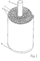
- the drainage and / or degassing area is designated by 1 in FIGS. It consists of a shaped body which consists of a plurality of threads of melt-spun polymer which lie in loops and cross one another and have a thread diameter of at least 0.1 mm and which are glued to one another at their crossing points.
- a plurality of shaped bodies 1 - three of which are shown in FIG. 1 - are pushed onto a support tube 2 in succession. On the outside, the shaped bodies are covered by a filter layer, for example a fleece.
- the support tube 2 is coupled to a base plate 4.
- the dome shown there contains a support tube 2 and a footplate 4 coupled to this support tube.
- the drainage and / or degassing area in the case shown consists of a mat 5 wrapped around the support tube, which is laminated on one side with a fleece 6.
- the mat 5 in turn consists of a large number of crossing threads of melt-spun polymer lying in loops, which are glued together at their crossing points.
- Such mats can be obtained commercially in the roll form shown and can be pushed over the support tube without further precautions.
- the support tube 2 can be extended and further mat rolls 5/6 can be pushed on. This can happen so often be repeated until the cathedral reaches into the head of the landfill.
- domes in the head area and in the bottom area of the landfill are connected to each other with cross tubes.
Landscapes
- Engineering & Computer Science (AREA)
- Life Sciences & Earth Sciences (AREA)
- Environmental & Geological Engineering (AREA)
- Mining & Mineral Resources (AREA)
- General Life Sciences & Earth Sciences (AREA)
- Geology (AREA)
- Geochemistry & Mineralogy (AREA)
- Fluid Mechanics (AREA)
- Physics & Mathematics (AREA)
- Hydrology & Water Resources (AREA)
- Paleontology (AREA)
- Civil Engineering (AREA)
- General Engineering & Computer Science (AREA)
- Structural Engineering (AREA)
- Processing Of Solid Wastes (AREA)
- Filtering Materials (AREA)
- Rigid Pipes And Flexible Pipes (AREA)
- Biological Treatment Of Waste Water (AREA)
Applications Claiming Priority (2)
| Application Number | Priority Date | Filing Date | Title |
|---|---|---|---|
| DE3719208 | 1987-06-09 | ||
| DE3719208 | 1987-06-09 |
Publications (2)
| Publication Number | Publication Date |
|---|---|
| EP0294656A2 true EP0294656A2 (fr) | 1988-12-14 |
| EP0294656A3 EP0294656A3 (fr) | 1990-03-21 |
Family
ID=6329324
Family Applications (1)
| Application Number | Title | Priority Date | Filing Date |
|---|---|---|---|
| EP88108401A Withdrawn EP0294656A3 (fr) | 1987-06-09 | 1988-05-26 | Puits pour décharge de déchets |
Country Status (2)
| Country | Link |
|---|---|
| US (1) | US4946310A (fr) |
| EP (1) | EP0294656A3 (fr) |
Cited By (5)
| Publication number | Priority date | Publication date | Assignee | Title |
|---|---|---|---|---|
| US5261766A (en) * | 1991-09-06 | 1993-11-16 | Anderson James S | Vertical bore hole system and method for waste storage and energy recovery |
| EP0620325A1 (fr) * | 1993-03-25 | 1994-10-19 | Claymax Corporation | Revêtement en argile avec friction de surfaces améliorée |
| WO1996018022A1 (fr) * | 1994-12-07 | 1996-06-13 | Pall Corporation | Filtre pour puits souterrains |
| WO2010006638A3 (fr) * | 2008-07-14 | 2010-07-08 | Nv Bekaert Sa | Éléments filtrants |
| EP2361698A1 (fr) * | 2009-07-23 | 2011-08-31 | Enviro Seal Ltd | Raccord pour puits de gaz ainsi procédé pour son utilisation |
Families Citing this family (10)
| Publication number | Priority date | Publication date | Assignee | Title |
|---|---|---|---|---|
| US5277520A (en) * | 1991-12-06 | 1994-01-11 | The Tensar Corporation | Grid composite for backfill barriers and waste applications |
| US6804922B1 (en) | 1998-06-03 | 2004-10-19 | Construction Research & Technology Gmbh | Integral composite building material and uses therefor |
| US6131353A (en) * | 1998-06-03 | 2000-10-17 | Mbt Holding Ag | Composite weather barrier |
| US6745531B1 (en) | 2000-07-31 | 2004-06-08 | Construction Research & Technology Gmbh | Pressure equalized compartment for exterior insulation and finish system |
| US7786026B2 (en) * | 2003-12-19 | 2010-08-31 | Saint-Gobain Technical Fabrics America, Inc. | Enhanced thickness fabric and method of making same |
| US7625827B2 (en) * | 2003-12-19 | 2009-12-01 | Basf Construction Chemicals, Llc | Exterior finishing system and building wall containing a corrosion-resistant enhanced thickness fabric and method of constructing same |
| US20060101758A1 (en) * | 2004-11-18 | 2006-05-18 | Egan William F | Composite building material |
| US20060245830A1 (en) * | 2005-04-27 | 2006-11-02 | Jon Woolstencroft | Reinforcement membrane and methods of manufacture and use |
| MX2010008763A (es) * | 2008-02-11 | 2010-09-07 | Marc-Antonie Pelletier | Sistema y metodo de extraccion de gas y liquido. |
| US10661319B2 (en) * | 2017-12-28 | 2020-05-26 | Republic Services, Inc. | Gas ventilation and leachate drain assemblage for landfill |
Family Cites Families (29)
| Publication number | Priority date | Publication date | Assignee | Title |
|---|---|---|---|---|
| DE7137887U (de) * | 1972-02-10 | Naue E Kg | Flexibles Drainrohr | |
| US231066A (en) * | 1880-08-10 | Filter | ||
| DE7145370U (fr) * | 1900-01-01 | Akzo Gmbh | ||
| DE7424845U (de) * | 1974-11-28 | Hoechst Ag | Dränrohr | |
| DE7319981U (de) * | 1973-11-08 | Lutravil Spinnvlies Gmbh & Co | Filtermatte zur Filtersicherung bei Flachendrainagen | |
| DE7241052U (de) * | 1973-03-08 | Schoennebecker Brunnenfilter Gmbh | Dränrohr mit Ummantelung | |
| US1490920A (en) * | 1923-02-27 | 1924-04-22 | Ernest R Godward | Vaporizer for volatile-fuel mixtures |
| US3112262A (en) * | 1960-07-12 | 1963-11-26 | New York Business Dev Corp | Filter unit and filter cartridge therefor |
| US3186552A (en) * | 1962-12-12 | 1965-06-01 | Filters Inc | Filter element end cap |
| GB1253117A (fr) * | 1969-09-26 | 1971-11-10 | ||
| DE2037831A1 (de) * | 1970-07-30 | 1972-02-03 | Glanzstoff AG, 5600 Wuppertal | Filtermaterial |
| US3807570A (en) * | 1972-09-29 | 1974-04-30 | Carborundum Co | Slot depth filter element |
| DE2327618A1 (de) * | 1973-05-16 | 1974-12-05 | Naue Kg E A H | Grossflaechiges mehrschichten-draenageelement |
| US4048075A (en) * | 1974-05-06 | 1977-09-13 | The Carborundum Company | Filter cartridge |
| DE2530499C3 (de) * | 1975-07-09 | 1978-05-24 | Akzo Gmbh, 5600 Wuppertal | Mattenbahn und Verfahren zu ihrer Herstellung |
| DE2720403C2 (de) * | 1975-07-09 | 1983-09-22 | Akzo Gmbh, 5600 Wuppertal | Verbund-Mattenbahn, Verfahren und Vorrichtung zu ihrer Herstellung |
| JPS5289239A (en) * | 1976-01-21 | 1977-07-26 | Tadaki Morimura | Method of treating waste water |
| DE2606921B2 (de) * | 1976-02-20 | 1979-04-26 | Oltmanns, Heinrich, 2905 Edewecht | Filtermatte für den Wasserbau und die Ummantelung von Dränrohren |
| FR2442921A1 (fr) * | 1978-11-30 | 1980-06-27 | Rhone Poulenc Textile | Complexe textile pour drainage |
| FR2524351B1 (fr) * | 1982-04-06 | 1985-10-31 | Celmetanche | Procede et installation pour le captage des gaz et eaux percolees dans les decharges compactees de residus urbains ou autres |
| DE3306665A1 (de) * | 1983-02-25 | 1983-07-21 | Karl Dipl.-Ing. 5000 Köln Wagner | Verfahren zur aktiven entgasung einer deponie |
| SE435682B (sv) * | 1983-03-09 | 1984-10-15 | Gullfiber Ab | Rorfilter, avsett i forsta hand for filtrering av vetskor rorfilter, avsett i forsta hand for filtrering av vetskor |
| DE3313053A1 (de) * | 1983-04-12 | 1984-11-15 | Eduard Luxemburg Colangelo | Vorrichtung zum schutz von drainagerohren |
| FR2555215B1 (fr) * | 1983-11-23 | 1986-04-11 | Induplast Sa | Dispositif de recuperation d'un liquide |
| DE3425786A1 (de) * | 1984-07-13 | 1986-01-23 | Reinhard 6300 Giessen Schneider | Vorrichtung zur speicherung von deponiegas in muelldeponien |
| DE3425784A1 (de) * | 1984-07-13 | 1986-01-23 | Reinhard 6300 Giessen Schneider | Muelldeponie mit brunnen zum sammeln und abfuehren der zersetzungsgase |
| DE3609973A1 (de) * | 1985-04-01 | 1986-10-09 | Basf Ag, 6700 Ludwigshafen | Sickerwassersammelschacht fuer deponien |
| DE3533135A1 (de) * | 1985-09-17 | 1987-03-19 | Mst Maschinenbau Gmbh | Verfahren und vorrichtung zum ummanteln von draenagerohren |
| JPS64363A (en) * | 1987-06-23 | 1989-01-05 | Hitachi Ltd | Protective device for hydraulic machine |
-
1988
- 1988-05-26 EP EP88108401A patent/EP0294656A3/fr not_active Withdrawn
- 1988-06-06 US US07/202,543 patent/US4946310A/en not_active Expired - Fee Related
Cited By (7)
| Publication number | Priority date | Publication date | Assignee | Title |
|---|---|---|---|---|
| US5261766A (en) * | 1991-09-06 | 1993-11-16 | Anderson James S | Vertical bore hole system and method for waste storage and energy recovery |
| EP0620325A1 (fr) * | 1993-03-25 | 1994-10-19 | Claymax Corporation | Revêtement en argile avec friction de surfaces améliorée |
| US5664628A (en) * | 1993-05-25 | 1997-09-09 | Pall Corporation | Filter for subterranean wells |
| US5909773A (en) * | 1993-05-25 | 1999-06-08 | Pall Corporation | Method of repairing a damaged well |
| WO1996018022A1 (fr) * | 1994-12-07 | 1996-06-13 | Pall Corporation | Filtre pour puits souterrains |
| WO2010006638A3 (fr) * | 2008-07-14 | 2010-07-08 | Nv Bekaert Sa | Éléments filtrants |
| EP2361698A1 (fr) * | 2009-07-23 | 2011-08-31 | Enviro Seal Ltd | Raccord pour puits de gaz ainsi procédé pour son utilisation |
Also Published As
| Publication number | Publication date |
|---|---|
| EP0294656A3 (fr) | 1990-03-21 |
| US4946310A (en) | 1990-08-07 |
Similar Documents
| Publication | Publication Date | Title |
|---|---|---|
| EP0294656A2 (fr) | Puits pour décharge de déchets | |
| DE3874363T2 (de) | Draenagematerial und draenagekern fuer draenagesystem. | |
| DE1684357B2 (de) | Schalung zur herstellung von betonwaenden oder dergleichen | |
| DE2159902C3 (de) | Verfahren und Vorrichtung zum Herstellen einer mehrschichtigen rohrförmigen Kunststoff-Tragstruktur | |
| DE2852108A1 (de) | Rohrbrunnenfilter | |
| DE2346242A1 (de) | Herstellungsverfahren fuer zylindrische hohlkoerper mit tragstruktur aus warmhaertendem verstaerkten harz und nach diesem verfahren hergestellter zylindrischer hohlkoerper | |
| EP3690159A1 (fr) | Enveloppe de bâtiment et procédé d'isolement thermique des enveloppes de bâtiment en béton | |
| DE2636531C2 (de) | Fertigbauelement | |
| DE2702043B2 (de) | Füllkörper für Abwasserbehandlungsbehälter und Verfahren zu dessen Herstellung | |
| DE4224042A1 (de) | Verfahren und Vorrichtung zur Pfahlgründung | |
| DE19542510A1 (de) | Gitterblockmaterial | |
| DE3816670A1 (de) | Dom fuer deponien | |
| DE1301300B (de) | Filterrohr mit einem Grundkoerper aus Asbestzement oder Kunststoff | |
| DE2001509B2 (de) | Hohlzylindrischer Filtereinsatz | |
| DE2639792A1 (de) | Verfahren zur oertlichen erhoehung der tragfaehigkeit von lockerem boden | |
| DE69001776T2 (de) | Geformte Platteneinheit und mit diesen Platteneinheiten versehene Quellwasserbehandlungsstruktur. | |
| DE2433975A1 (de) | Bahnenmaterial fuer entwaesserungszwecke | |
| EP1307326B1 (fr) | Dalle creuse en beton precontraint et son procede de fabrication | |
| DE102010024607A1 (de) | Gründungspfahl sowie Verfahren zu seiner Herstellung | |
| DE4110827C2 (de) | Plattenmaterial für Bauzwecke sowie Verfahren zu dessen Herstellung | |
| CH662600A5 (de) | Verfahren zur herstellung eines armierten mauerwerkes sowie mauerstein und armierungsbuegel zur ausfuehrung des verfahrens. | |
| DE2454274C2 (de) | Verfahren zum Herstellen einer selbsttragenden kuppelartigen Betonkonstruktion sowie Vorrichtung zur Durchführung des Verfahrens | |
| EP3282063B1 (fr) | Treillis métallique pourvu de corps de pression ainsi que structure de chaussée | |
| DE3610949A1 (de) | Verfahren zur herstellung einer schmalwand in erdboeden, sowie dazu dienende einrichtungen und elemente | |
| DE1928471A1 (de) | Verfahren und Vorrichtung zur Verdichtung und Entwaesserung von Boeden |
Legal Events
| Date | Code | Title | Description |
|---|---|---|---|
| PUAI | Public reference made under article 153(3) epc to a published international application that has entered the european phase |
Free format text: ORIGINAL CODE: 0009012 |
|
| AK | Designated contracting states |
Kind code of ref document: A2 Designated state(s): AT BE CH DE ES FR GB GR IT LI LU NL SE |
|
| PUAL | Search report despatched |
Free format text: ORIGINAL CODE: 0009013 |
|
| AK | Designated contracting states |
Kind code of ref document: A3 Designated state(s): AT BE CH DE ES FR GB GR IT LI LU NL SE |
|
| 17P | Request for examination filed |
Effective date: 19900912 |
|
| 17Q | First examination report despatched |
Effective date: 19911203 |
|
| STAA | Information on the status of an ep patent application or granted ep patent |
Free format text: STATUS: THE APPLICATION IS DEEMED TO BE WITHDRAWN |
|
| 18D | Application deemed to be withdrawn |
Effective date: 19920403 |