EP0293573A1 - System zum Erkennen und Regeln des Klopfens einer Brennkraftmaschine - Google Patents
System zum Erkennen und Regeln des Klopfens einer Brennkraftmaschine Download PDFInfo
- Publication number
- EP0293573A1 EP0293573A1 EP88105406A EP88105406A EP0293573A1 EP 0293573 A1 EP0293573 A1 EP 0293573A1 EP 88105406 A EP88105406 A EP 88105406A EP 88105406 A EP88105406 A EP 88105406A EP 0293573 A1 EP0293573 A1 EP 0293573A1
- Authority
- EP
- European Patent Office
- Prior art keywords
- knock
- engine
- output
- value
- maximum
- Prior art date
- Legal status (The legal status is an assumption and is not a legal conclusion. Google has not performed a legal analysis and makes no representation as to the accuracy of the status listed.)
- Granted
Links
Images


Classifications
-
- F—MECHANICAL ENGINEERING; LIGHTING; HEATING; WEAPONS; BLASTING
- F02—COMBUSTION ENGINES; HOT-GAS OR COMBUSTION-PRODUCT ENGINE PLANTS
- F02P—IGNITION, OTHER THAN COMPRESSION IGNITION, FOR INTERNAL-COMBUSTION ENGINES; TESTING OF IGNITION TIMING IN COMPRESSION-IGNITION ENGINES
- F02P5/00—Advancing or retarding ignition; Control therefor
- F02P5/04—Advancing or retarding ignition; Control therefor automatically, as a function of the working conditions of the engine or vehicle or of the atmospheric conditions
- F02P5/145—Advancing or retarding ignition; Control therefor automatically, as a function of the working conditions of the engine or vehicle or of the atmospheric conditions using electrical means
- F02P5/15—Digital data processing
- F02P5/152—Digital data processing dependent on pinking
-
- G—PHYSICS
- G01—MEASURING; TESTING
- G01L—MEASURING FORCE, STRESS, TORQUE, WORK, MECHANICAL POWER, MECHANICAL EFFICIENCY, OR FLUID PRESSURE
- G01L23/00—Devices or apparatus for measuring or indicating or recording rapid changes, such as oscillations, in the pressure of steam, gas, or liquid; Indicators for determining work or energy of steam, internal-combustion, or other fluid-pressure engines from the condition of the working fluid
- G01L23/22—Devices or apparatus for measuring or indicating or recording rapid changes, such as oscillations, in the pressure of steam, gas, or liquid; Indicators for determining work or energy of steam, internal-combustion, or other fluid-pressure engines from the condition of the working fluid for detecting or indicating knocks in internal-combustion engines; Units comprising pressure-sensitive members combined with ignitors for firing internal-combustion engines
- G01L23/221—Devices or apparatus for measuring or indicating or recording rapid changes, such as oscillations, in the pressure of steam, gas, or liquid; Indicators for determining work or energy of steam, internal-combustion, or other fluid-pressure engines from the condition of the working fluid for detecting or indicating knocks in internal-combustion engines; Units comprising pressure-sensitive members combined with ignitors for firing internal-combustion engines for detecting or indicating knocks in internal combustion engines
- G01L23/225—Devices or apparatus for measuring or indicating or recording rapid changes, such as oscillations, in the pressure of steam, gas, or liquid; Indicators for determining work or energy of steam, internal-combustion, or other fluid-pressure engines from the condition of the working fluid for detecting or indicating knocks in internal-combustion engines; Units comprising pressure-sensitive members combined with ignitors for firing internal-combustion engines for detecting or indicating knocks in internal combustion engines circuit arrangements therefor
-
- Y—GENERAL TAGGING OF NEW TECHNOLOGICAL DEVELOPMENTS; GENERAL TAGGING OF CROSS-SECTIONAL TECHNOLOGIES SPANNING OVER SEVERAL SECTIONS OF THE IPC; TECHNICAL SUBJECTS COVERED BY FORMER USPC CROSS-REFERENCE ART COLLECTIONS [XRACs] AND DIGESTS
- Y02—TECHNOLOGIES OR APPLICATIONS FOR MITIGATION OR ADAPTATION AGAINST CLIMATE CHANGE
- Y02T—CLIMATE CHANGE MITIGATION TECHNOLOGIES RELATED TO TRANSPORTATION
- Y02T10/00—Road transport of goods or passengers
- Y02T10/10—Internal combustion engine [ICE] based vehicles
- Y02T10/40—Engine management systems
Definitions
- This invention relates to an engine knock control system which detects engine knock occurrence and controls the ignition timing or the like to prevent engine knock. Further, this invention relates to an engine knock detecting system for detecting engine knock occurrence.
- the output of the knocking sensor during nonknocking operation bears noise normally generated by operation of the engine including, for instance, noise generated by opening and closure of the valves, and accordingly, when knocking occurs, the output of the knocking sensor comes to bear oscillation due to the knock (knock signal) superposed on such background noise. Therefore, the reference level must be accurately set between the output level of the sensor solely bearing the background noise and that bearing both the background noise and the knock signal. Otherwise knock detecting accuracy is deteriorated to adversely affect knock control.
- both the background noise and the knock signal vary from engine to engine, and differ according to change of the engine with time, the engine speed, the environmental temperature and the like. Further, they are affected by detecting accuracy of a given knocking sensor, change of the knocking sensor with time, and the like. Accordingly, when the reference level is set to a constant level, the background noise can be mistaken for the knock signal or knock occurrence cannot be precisely detected, whereby the engine output can be unnecessarily suppressed or the engine knock cannot be suppressed to adversely affect the engine durability.
- the primary object of the present invention is to provide a knock control system which can precisely detect knock occurrence without affected by the background noise and can control occurrence of knock with high accuracy.
- Another object of the present invention is to provide a knock detecting system which can precisely detect knock occurrence without affected by the background noise.
- oscillation of the engine is detected by an oscillation sensor which outputs a signal representing the oscillation of the engine, and the maximum value of the output of the oscillation sensor during combustion period in each cycle is detected by a maximum value detecting means.
- the maximum values obtained in a predetermined number of cycles are stored in a memory and knock occurrence is determined on the basis of the predetermined number of maximum values output from the memory.
- the maximum value of the output signal of the oscillation sensor in a predetermined period during which knock occurs is obtained and the average of a predetermined number of maximum values is obtained through a statistical process.
- the average thus obtained substantially falls on the center of the normal distribution of the background noise.
- a reference level obtained by multiplying the average by a coefficient preset according to the engine speed and the charged volume is stored in a learning map and is output to a comparator according to the operating condition.
- the maximum value is detected a plurality of times and a maximum frequency value which is the value of the maximum value which appears most frequently is statistically obtained on the basis of the frequency distribution characteristics. Then the reference level is set on the basis of the distribution width on the lower level side of the maximum frequency value.
- the maximum value is detected a plurality of times and a maximum frequency which is the number of the maximum values which appear most frequently is statistically obtained on the basis of the frequency distribution characteristics. Then the reference level is set on the basis of the average of the maximum values and the maximum frequency.
- the maximum value is detected a plurality of times and a maximum frequency value which is the value of the maximum value which appears most frequently is statistically obtained on the basis of the frequency distribution characteristics. Then the reference level is set on the basis of the maximum frequency value.
- an engine 1 has a combustion chamber 11 provided with a spark plug 3.
- the spark plug 3 is connected to an ignition coil 13 by way of a distributor 12.
- An ignition signal is input into the ignition coil 13 from an engine control unit 14 to control the ignition timing.
- An intake passage 17 opens to the combustion chamber 11 by way of an intake valve 16, and an airflow meter 18 for detecting the amount of intake air, a throttle valve 19, a fuel injector 20 are provided in the intake passage 17 in this order from the upstream side of the intake passage 17. Further, an exhaust passage 22 opens to the combustion chamber 11 by way of an exhaust valve 21. The exhaust passage 22 is provided with a catalytic converter 23. A knocking sensor 4 is provided to detect engine oscillation. A first crank angle sensor 25 which outputs a first crank angle signal at a predetermined crank angle (60 to 90 degrees ATDC) and a second crank angle sensor 26 which outputs a second crank angle signal at another predetermined crank angle (30 to 0 degrees BTDC) are mounted on the distributor 12. The first and second crank angle signals from the sensor 25 and 26 are input into the engine control unit 14.
- the engine control unit 14 determines a basic ignition timing on the basis of the engine speed and the engine load according to the signals from various sensors.
- the engine control unit 14 detects knock occurrence on the basis of comparison of the detecting signal of the knocking sensor 4 with a reference level based on a learning value, and retards the ignition timing to suppress knock when knock occurs while sets a feedback correction to gradually advance the ignition timing when knock occurrence is not detected.
- the maximum value of the output of the knocking sensor 4 (peak voltage) during the knock occurrence period near TDC is input into the engine control unit 14 a predetermined times, and the engine control unit 14 averages the maximum values and updates the learning value for the reference level by multiplying the average of the maximum values by a predetermined coefficient.
- the final ignition timing is set on the basis of the basic ignition timing and the feedback correction value.
- the engine control unit 14 comprises a CPU 28, a ROM 29 in which operational program is stored, a RAM 30 for storing the learning value and the like, a free running counter 31 and first to third PTMs (program timer) 32 to 34 which sets times under the control of the CPU 28.
- the first and second crank angle signals are input into the CPU 28 as interruption signals by way of a waveform shaping circuit 35.
- an intake air amount signal from the airflow meter 18 and the detecting signal of the knocking sensor 4 by way of an analog buffer 36 and an A/D convertor 37.
- the detecting signal of the knocking sensor 4 is processed by a knock detecting circuit 38 (shown in detail in Figure 4) of the analog buffer 36 on the basis of a gate signal GA from the first and second PTMs 32 and 33, a reference level signal Vre from a D/A convertor 39, reset signals R1 and R2 from an output port 40 and gain control signals G1 and G2, and a maximum value signal Vp (peak voltage) during the knock occurrence period and a knock intensity signal Ik (integral voltage) as the result of comparison are input into the CPU 28.
- the third PTM 34 is set according to an ignition timing as the result of operation of the CPU 28, and is triggered by the first crank angle signal from the first crank angle sensor 25.
- the output signal of the third PTM 34 is delivered to the ignition coil 13 as an ignition signal by way of an output interface 41.
- the knock detecting circuit 38 includes a BPF (bandpass filter) 45 which receives the detecting signal of the knocking sensor 4 and extracts the knock frequency component.
- the bandpass filtered signal is amplified by an input AMP 46, and only the bandpass filtered signal during the knock occurrence period (from 10 degrees to 50 degrees ATDC) is input into a peak holding circuit 48 and a comparator 49 in response to gate opening and closing operation of an analog switch 47 under the control of said gate signal GA.
- the peak holding circuit 48 holds the peak value during the gate opening time, thereby obtaining the maximum value Vp and is reset by the reset signal R1.
- the comparator 49 Into the comparator 49 is input the reference level signal Vre, and the bandpass filtered signal higher than the reference level signal Vre is input into an integrator 50 and an integrated value Ik (the knock intensity signal) during the gate opening time is obtained.
- the integrator 50 is reset by the reset signal R2.
- the output of the knocking sensor 4 changes according the engine speed, and accordingly, in order to stabilize the output of the input AMP 46 within a predetermined range, the gain control signals G1 and G2 are input, according to the engine speed, respectively into analog switches 51 and 52 (which are provided for gain control resistors connected in parallel to the input AMP 46) to open and close the switches 51 and 52, thereby controlling the gain of the input AMP 46.
- Step S1 is an initialization step.
- step S2 the engine speed Ne is calculated on the basis of TDC cycle To derived from the crank angle signal.
- step S3 the intake air amount Qa is read from the output of the airflow meter 18.
- the charged volume Ce representing the engine load is calculated on the basis of the engine speed Ne and the intake air amount Qa, and a basic ignition timing Ab is calculated from a basic map in which the engine speed Ne and the charged volume Ce are related.
- step S6 it is determined whether the operating condition is in the knock zone on the basis of the charged volume Ce.
- a knock control flag Fk is set to 1 in step S7, and then the present learning zone Zjk is obtained from a zone map of the engine speed Ne and the charged volume Ce in step S8.
- step S9 a learning value Ljk is read from a learning map corresponding to the present learning zone Zjk.
- the learning value Ljk is converted into a voltage Vre as the reference level and delivered to the D/A convertor 39.
- the operating condition is zoned into a plurality of zones Zjk on the basis of the engine speed Ne and the charged volume Ce, and in the learning map, the learning values Ljk of the reference level are stored in zones corresponding to the zone map as shown in Figure 8.
- step S11 the rate of change Dc in the charged volume Ce on the basis of the difference between the present charged volume Ce and the preceding charged volume Cb, and then in step S12, the preceding charged volume Cb is updated.
- step S13 it is determined whether the vehicle is accelerated on the basis of whether the rate of change Dc in the charged volume Ce is not smaller than a predetermined value Dco.
- the number Na of the maximum values to be averaged is set to a relatively small value, i.e., 30 in this particular embodiment in order to obtain better response in step S14.
- the number Na of the maximum values to be averaged is set to a relatively large value, i.e., 100 in this particular embodiment in order to obtain better control stability in step S15.
- Steps S16 to S20 are for controlling the gain of the input AMP 46 according to the engine speed Ne.
- the step S16 it is determined whether the engine speed Ne is in the high speed range higher than 4500rpm, and in the step S17, it is determined whether the engine speed Ne is in the intermediate speed range between 2000 rpm and 4500 rpm.
- the gate signals G1 and G2 are turned to high level in the step S18 to close the analog switches 51 and 52 so that the gain of the input AMP becomes small.
- Step S19 When it is determined that the engine speed is in the low speed range, the gate signal G1 is turned to high level to close the analog switch 51 and the gate signal G2 is turned to low level to open the analog switch 52 so that the gain of the input AMP 46 becomes intermediate.
- Step S19 When it is determined that the engine speed Ne is in the low speed range, both the gate signals G1 and G2 are turned to low level to open both the analog switches 51 and 52 so that the gain of the input AMP 46 becomes large.
- step S6 When it is determined in the step S6 that the operating condition is not in the knock zone, the flow proceeds to step S21 and the knock control flag Fk is cleared to 0.
- FIG. 6 shows an interrupt routine which is started by a signal input every 60 degrees ATDC.
- an interrupt time T1 is read from the free running counter 31, and in step S23, the TDC cycle To, the time required for the crankshaft to make a half revolution (180°), is calculated on the basis of the difference between the present interrupt time T1 and the preceding interrupt time T2. Thereafter, the preceding interrupt time T2 is updated in step S24.
- step S25 it is determined on the basis of the knock control flag Fk set in the main routine whether the operating condition is in the knock zone.
- the knock intensity Ik is read from the knock detecting circuit 38 in step S26, and a reset signal R2 at low level is input into the integrator 50 to reset the knock intensity Ik in step S27.
- the feedback correction value Afb is cleared to 0 in step S28.
- step S29 it is determined whether knock occurs on the basis of whether the knock intensity Ik is detected.
- the feedback correction value Afb is corrected to advance the ignition timing by a predetermined value in step S31.
- the maximum value Vp peak voltage
- step S32 a reset signal R1 at low level is output to the peak holding circuit 48 to reset the maximum value Vp.
- a cumulative value Vt of the maximum values Vp is obtained and the number Nc of the maximum values Vp cumulated is calculated.
- step S36 it is determined whether the number Nc of the cumulated maximum values Vp reaches the number Na set in the step S14 or S15 (30 or 100), thereby determining whether learning is completed.
- a reference level preparation coefficient Cj corresponding to the present learning zone Zjk is read from a map in step S37.
- the coefficients Cj are allocated to respective zones, which are divided according to the engine speed Ne and the charged volume Ce corresponding to the zones in the learning map, so that the value of the coefficient Cj allocated to a given zone is reduced as the engine speed Ne increases and increased as the charged volume Ce increase. That is, the coefficient Cj is for obtaining a level corresponding to the noise distribution width from the average, and is set taking into account the fact that the noise distribution width becomes narrower as the engine speed Ne increases and becomes wider as the charged volume Ce increases.
- step S38 the learning value Ljk of the present learning zone Zjk is updated on the basis of the average of the maximum values Vp (cumulative value Vt/the number of the cumulated maximum values Vp) and the coefficient Cj, and in step S39, registers Nc, Vt for learning are cleared.
- This updating of the learning value Ljk is effected by multiplying 5% of the average Vt/Nc by coefficient (l+Cj) and adding the product to 95% of the preceding learning value to avoid large fluctuation of the learning value.
- step S40 On the basis of the basic ignition timing Ab and the feedback correction value Afb obtained in the manner described above, the final ignition timing As is calculated in step S40.
- step S41 the time Tc between 90 degrees BTDC at which the first crank angle signal from the first crank angle sensor 25 turns to low level and the final ignition timing As (energizing time) is calculated, and in step S42, the third PTM 34 is set according to the energizing time.
- the third PTM 34 is triggered by the crank angle signal at 90 degrees BTDC and the ignition signal is output after the time Tc.
- FIG. 7 shows a second interrupt routine which starts every 30 degrees BTDC and which is for setting and outputing the gate signal GA for the analog switch 47 in the knock detecting circuit 38.
- step S43 the time interval Tgo from the TDC to 10 degrees ATDC at which the analog switch 47 is opened is calculated, and in step S44, the time interval Tgc from 10 degrees ATDC to 50 degrees ATDC at which the analog switch 47 is closed is calculated.
- step S45 the time intervals Tgo and Tgc are respectively output to the first and second PTMs 32 and 33 to open the analog switch 47 Tgo after TDC and to close the same Tgc thereafter, thereby preventing noise generated by closure of the intake valve from being input into the peak holding circuit 48 and the comparator 48.
- reset signals R1 and R2 at high level are output to the integrator 50 and the peak holding circuit 48, which have been reset at the steps S27 and S33, to enable them to operate.
- the maximum value Vp of the detecting signal of the knocking sensor 4 in a predetermined period during which knock occurs is obtained and the average of a predetermined number of maximum values Vp is obtained through a statistical process.
- the average thus obtained substantially falls on the center of the normal distribution of the background noise.
- a reference level obtained by multiplying the average by the coefficient Cj preset according to the engine speed and the charged volume is stored in the learning map and is output to the comparator 49 according to the operating condition.
- the comparator 49 compares the reference level with the output of the knocking sensor 4 and outputs to the integrator a signal the voltage of which changes according to the knock intensity. According to the output signal, the ignition timing is feedback-controlled to suppress the knock.
- the maximum value Vp is detected a plurality of times and a maximum frequency value Vpm which is the value of the maximum value Vp which appears most frequently is statistically obtained on the basis of the frequency distribution characteristics. Then the reference level is set on the basis of the distribution width on the lower level side of the maximum frequency value Vpm.
- the second embodiment is substantially the same as the first embodiment in the mechanical and electronic arrangement except that the control to be made by the control unit differs from that of the first embodiment and that the knock detecting circuit 38 is not provided with the comparator 49 and the integrator 50 and knock occurrence is detected on the basis of the maximum value Vp.
- gain control of the input AMP 46 and gate control for the analog switch 47 are omitted.
- Step S49 is an initialization step.
- step S50 the intake air amount Qa is read from the output of the airflow meter 18.
- a basic ignition timing Ab ignition advancing angle
- step S52 it is determined whether the operating condition is in the knock zone on the basis of whether the charged volume Ce is larger than a predetermined value Ceo.
- a knock control flag Fk is set to 1 in step S53, and then the operating zone Zjk is calculated from the engine speed Ne and the charged volume Ce in step S54.
- the knock control flag Fk is cleared to 0 in step S55.
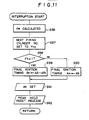
- FIG 11 shows an interrupt routine.
- the engine speed Ne is calculated on the basis of the interruption cycle To.
- the number of next firing cylinder is set to a cylinder flag Fcy on the basis of a signal from a cylinder sensor, for instance.
- the knock control flag Fk is 1, thereby determining whether the operating condition is in the knock zone.
- the basic ignition timing Ab is corrected by a feedback correction value Afb obtained in a second interrupt routine to be described later, thereby obtaining a final ignition timing As in step S59. Otherwise, the basic ignition timing Ab is adopted as the final ignition timing As as it is.
- PTM 34 is set on the basis of the ignition time calculated from the final ignition timing As in step S61, and the peak holding circuit is released in step S62.
- Figure 12 shows a second interrupt routine.
- the maximum value Vp of the output of the knocking sensor 4 during the knock occurrence period is read in step S63.
- step S64 it is determined whether the knock control flag Fk is 1, thereby determining whether the operating condition is in the knock zone.
- the present operating zone Zjk has ever learned in step S65.
- the reference level Ljk for the present cylinder number Fcy is read from the learning map in step S66.
- the reference level Ljk for the present cylinder number Fcy is read from an initial value map in step S67.
- step S68 it is determined whether the maximum value Vp is larger than the reference level Ljk.
- the feedback correction value Afb is corrected to retard the ignition timing by adding to the feedback correction value Afb the product of the difference between the maximum value Vp and the reference level Ljk and a predetermined coefficient ⁇ in step S69.
- step S70 it is determined whether the corrected feedback correction value Afb is larger than an upper limit Amax.
- the feedback correction value Afb is limited to the upper limit Amax in step S71.
- step S68 when it is determined in the step S68 that knock does not occur, the feedback correction value Afb is corrected to advance the ignition timing by subtracting a predetermined value Aad from the feedback correction value Afb in step S72. Then in step S73, it is determined whether the corrected feedback correction value Afb is larger than 0. When it is determined that the former is smaller than the latter, the feedback correction value Afb is limited to 0 in step S74.
- step S75 it is determined whether the present operating zone Zjk is the same as the preceding operating zone.
- the memory value Mi corresponding to the level of the present maximum value Vp input into a memory for distribution calculation is incremented, the frequency of the maximum value Vp of the level is obtained and the number Nc of the cumulated maximum values Vp is calculated in order to calculate the distribution for the maximum values Vp.
- step S78 it is determined whether learning is completed on the basis of whether the number of the cumulated maximum values Vp reaches a predetermined value No.
- the maximum value Vmp corresponding to the maximum point Mm at which the frequency for the maximum value Vp is maximum is retrieved from the memory for distribution calculation.
- this retrieval can be effected by repeating comparison of a pair of memory values Mi with each other while eliminating smaller ones and adopting as the maximum frequency value Vpm the output level corresponding to the memory number of the memory value Mm determined to be larger at the final comparison.
- step S80 the standard deviation ⁇ in the distribution obtained by folding back the distribution on the lower level side of the maximum frequency value Vpm in the maximum value distribution (See Figure 13) toward the higher level side at the maximum frequency value Vpm is obtained, or in other words, the background noise distribution is obtained.
- step S81 the reference level Ljki is calculated for each cylinder. The reference level Ljki is obtained by adding the product of the standard deviation ⁇ and a cylinder coefficient Ki to the maximum frequency value Vpm.
- the reference levels Ljki for the respective cylinders are written in predetermined zones Zjk of a reference level learning map allocated to the respective cylinders to update the learning value in step S82. Then registers Mi and Nc for distribution calculation are cleared in step S83, the preceding zone Zjk is updated in step S84, and the peak holding circuit 48 is reset in step S85.
- the maximum frequency value Vpm which is hardly affected by presence of knock occurrence is obtained as the statistical characteristic value of the maximum value Vp, and the reference level Ljk is set for each cylinder, thereby further improving knock detecting accuracy and knock control accuracy.
- a third embodiment of the present invention will be described, hereinbelow, with reference to Figures 14 to 16.
- the maximum value Vp is detected a plurality of times and a maximum frequency Mm which is the number of the maximum values Vp which appear most frequently is statistically obtained on the basis of the frequency distribution characteristics. Then the reference level is set on the basis of the average of the maximum values Vp and the maximum frequency Mm.
- the third embodiment is substantially the same as the first embodiment in the mechanical and electronic arrangement except that the control to be made by the control unit differs from that of the first embodiment.
- Step S100 is an initialization step.
- a learning reflection permission flag Fre is set to 1. This flag Fre is for only once reflecting a change of the learning value Ljk for a learning zone Zjk on other learning zones when the learning zone Zjk learns for the first time after the engine is started and the learning value Ljk changes by an amount larger than a predetermined value.
- step S102 the intake air amount Qa is read from the output of the airflow meter 18.
- a basic ignition timing Ab is calculated on the basis of the intake air amount Qa and the engine speed Ne in step S103.
- step S104 it is determined whether the operating condition is in the knock zone on the basis of whether the charged volume Ce is larger than a predetermined value Ceo. When it is determined that the operation condition is in the knock zone, a knock control flag Fk is set to 1 in step S105, and then the operating zone Zjk is calculated from the engine speed Ne and the charged volume Ce in step S106. When it is determined in the step S104 that the operation condition is in nonknock zone, the knock control flag Fk is cleared to 0 in step S107.
- FIG. 15 shows an interrupt routine.
- the engine speed Ne is calculated on the basis of the interruption cycle To.
- step S109 it is determined whether the knock control flag Fk is 1, thereby determining whether the operating condition is in the knock zone.
- the basic ignition timing Ab is corrected by a feedback correction value Afb obtained in a second interrupt routine to be described later, thereby obtaining a final ignition timing As in step S110. Otherwise, the basic ignition timing Ab is adopted as the final ignition timing As as it is. (step S111)
- PTM 34 is set on the basis of the ignition time calculated from the final ignition timing As in step S112, and the peak holding circuit is released in step S113.
- Figure 16 shows a second interrupt routine.
- the maximum value Vp of the output of the knocking sensor 4 during the knock occurrence period is read in step S114.
- step S115 it is determined whether the knock control flag Fk is 1, thereby determining whether the operating condition is in the knock zone.
- the present operating zone Zjk has ever learned in step S116.
- the reference level Ljk for the present operating zone Zjk is read from the learning map in step S117.
- the reference level Ljk for the present operating zone Zjk is read from an initial value map in step S118.
- step S119 it is determined whether the maximum value Vp is larger than the reference level Ljk.
- the feedback correction value Afb is corrected to retard the ignition timing by adding to the feedback correction value Afb the product of the difference between the maximum value Vp and the reference level Ljk and a predetermined coefficient ⁇ in step S120.
- step S121 it is determined whether the corrected feedback correction value Afb is larger than an upper limit Amax.
- the feedback correction value Afb is limited to the upper limit Amax in step S122.
- step S119 when it is determined in the step S119 that knock does not occur, the feedback correction value Afb is corrected to advance the ignition timing by subtracting a predetermined value Aad from the feedback correction value Afb in step S123. Then in step S124, it is determined whether the corrected feedback correction value Afb is larger than 0. When it is determined that the former is smaller than the latter, the feedback correction value Afb is limited to 0 in step S125.
- step S126 it is determined whether the present operating zone Zjk is the same as the preceding operating zone.
- step S127 it is determined in step S127 whether the difference between the maximum value Vp and the reference level Ljk is larger than a predetermined value Skn. This step is for eliminating an excessively large maximum value Vp from calculation of the average value in order to reduce influence of excessively large knock and noise on the reference level.
- step S127 When it is determined in the step S127 that the difference between the maximum value Vp and the reference level Ljk is not larger than the predetermined value Skn, the memory value Mi corresponding to the level of the present maximum value Vp input into a memory for distribution calculation is incremented, the frequency of the maximum value Vp of the level is obtained and the number Nc of the cumulated maximum values Vp is calculated in order to calculate the distribution for the maximum values Vp. (steps S128 and S129)
- step S130 it is determined whether learning is completed on the basis of whether the number of the cumulated maximum values Vp reaches a predetermined value No.
- an average AVp of the maximum values Vp is calculated on the basis of a cumulative value Vt of the maximum values Vp in step 131.
- step S132 the maximum frequency Mm is obtained from the memory Mi of the frequency, and a coefficient K for calculating the reference value is calculated according to the value of the maximum frequency Mm. Since the standard deviation is apt to become small as the value of the maximum frequency Mm becomes large, the coefficient K is set to be smaller as the value of the maximum frequency Mm increases.
- the reference level Ljk is calculated on the basis of the average AVp and the coefficient K.
- the coefficient K is set to be inversely proportional to the maximum frequency Mm and the reference level Ljk is obtained by multiplying the average AVp by the coefficient so that the reference level Ljk is determined according to the distribution characteristics.
- Steps S134 to 139 are for reflecting the initial learning value for an operating zone to other operating zones.
- the step S134 it is determined whether the present operating zone Zjk has ever learned. When it is determined that the present operating zone Zjk has learned, it is determined whether the learning reflection permission flag Fre has been set to 1 in the step S135. When it is determined that the learning reflection permission signal Fre has been set to 1, it is determined in the step S136 whether the ratio of the reference level Ljk obtained at this time to the reference level Ljkm stored in the learning map is larger than a predetermined value Ra, and it is determined in the step S137 whether the ratio Ljk/Ljkm is smaller than a predetermined value Rb.
- the learning reference levels Ljkm for all the operating zones other the present operating zone are corrected using the ratio Ljk/Ljkm as a coefficient in the step S138, and the learning reflection permission flag Fre is cleared in the step S139.
- the reference level Ljk thus obtained is written in a predetermined zone Zjk of a reference level learning map allocated to the corresponding cylinder to update the learning value in step S140. Then registers Mi and Nc for distribution calculation are cleared in step S141, the preceding zone Zjk is updated in step S142, and the peak holding circuit 48 is reset in step S143.
- the average AVp and the maximum frequency Mm are obtained as statistical characteristic values of the maximum value Vp of the output of the knocking sensor 4, and the reference level Ljk is set by multiplying the average AVp by the coefficient K set on the basis of the maximum frequency Mm related to the distribution, thereby further improving knock detecting accuracy and knock control accuracy.
- a fourth embodiment of the present invention will be described with reference to Figures 18 to 22, hereinbelow.
- the fourth embodiment is substantially the same as the first embodiment in the mechanical and electronic arrangement except that the control to be made by the control unit differs from that of the first embodiment, and the knock detecting circuit is somewhat different from that shown in Figure 4 as shown in Figure 18.
- the maximum value Vp is detected a plurality of times and a maximum frequency value Vpm which is the value of the maximum value Vp which appears most frequently is statistically obtained on the basis of the frequency distribution characteristics. Then the reference level is set on the basis of the maximum frequency value Vpm.
- the knock detecting circuit 38 ⁇ shown in Figure 18 is substantially the same as that shown in Figure 4 except that the input AMP 46 is not provided with the analog switches 51 and 52 for controlling the gain thereof, and accordingly the analogous parts are given the same reference numerals and will not be described here.
- Step S201 is an initialization step.
- step S202 the engine speed Ne is calculated on the basis of TDC cycle To derived from the crank angle signal.
- step S203 the intake air amount Qa is read from the output of the airflow meter 18. Then the charged volume Ce representing the engine load is calculated on the basis of the engine speed Ne and the intake air amount Qa, and a basic ignition timing Ab is calculated from a basic map in which the engine speed Ne and the charged volume Ce are related.
- step S206 it is determined whether the operating condition is in the knock zone on the basis of the charged volume Ce.
- a knock control flag Fk is set to 1 in step S207, and then the present learning zone Zjk is obtained from a zone map of the engine speed Ne and the charged volume Ce in step S208.
- step S209 a learning value Ljk is read from a learning map corresponding to the present learning zone Zjk.
- the learning value Ljk is converted into a voltage Vre as the reference level and delivered to the D/A convertor 39.
- the zone map and the learning map may the same as those described above in conjunction with the first embodiment.
- step S211 it is determined whether the present learning zone Zjk is the same as the preceding learning zone.
- the flow directly proceeds to step S213, and otherwise, the flow proceeds to the step S213 after the learning memories Mi and Nc are cleared in step S212.
- the learning zone Zjk is updated.
- step S206 When it is determined in the step S206 that the operating condition is not in the knock zone, the flow proceeds to step S214 and the knock control flag Fk is cleared to 0. Further, the learning memories Mi and Nc are cleared in step S215.
- Figure 20 shows an interrupt routine which is started by a signal input every 60 degrees ATDC.
- an interrupt time T1 is read from the free running counter 31, and in step S217, the TDC cycle To, the time required for the crankshaft to make a half revolution (180°), is calculated on the basis of the difference between the present interrupt time T1 and the preceding interrupt time T2. Thereafter, the preceding interrupt time T2 is updated in step S218.
- step S219 it is determined on the basis of the knock control flag Fk set in the main routine whether the operating condition is in the knock zone.
- the knock intensity Ik is read from the knock detecting circuit 38 in step S220, and a reset signal R2 at low level is input into the integrator 50 to reset the knock intensity Ik in step S221.
- the feedback correction value Afb is cleared to 0 in step S222.
- step S223 it is determined whether knock occurs on the basis of whether the knock intensity Ik is detected.
- the feedback correction value Afb is corrected to advance the ignition timing by a predetermined value in step S225.
- the maximum value Vp peak voltage
- step S226 a reset signal R1 at low level is output to the peak holding circuit 48 to reset the maximum value Vp.
- the distribution for the maximum value Vp is calculated.
- the memory value Mi corresponding to the level (voltage) of the present maximum value Vp input into a memory for distribution calculation is incremented.
- the intensity of the output level is zoned into 100 zones, and registers are provided for the respective zone numbers i.
- the frequency of the maximum value Vp of a given level is obtained by incrementing the register of the corresponding number.
- step S229 the number Nc of the cumulated maximum values Vp is calculated.
- step S230 it is determined whether the number Nc of the cumulated maximum values Vp reaches a predetermined number, e.g., 1000, thereby determining whether learning is completed.
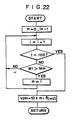
- the maximum value Vmp corresponding to the maximum point Mm at which the frequency for the maximum value Vp is maximum is retrieved from the memory for distribution calculation.
- this retrieval can be effected, as shown in sub routine in Figure 22, by repeating comparison of a pair of memory values Mi with each other while eliminating smaller ones and adopting as the maximum frequency value Vpm the output level corresponding to the memory number m of the memory value Mm determined to be larger at the final comparison.
- step S232 the learning value Ljk of the present learning zone Zjk is updated on the basis of the maximum frequency value Vpm, and in step S233, registers Mi and Nc for learning are cleared.
- This updating of the learning value Ljk is effected by multiplying 5% of the maximum frequency value Vpm by a predetermined coefficient (2) and adding the product to 95% of the preceding learning value to avoid large fluctuation of the learning value.
- the coefficient is for obtaining a level corresponding to the noise distribution width from the maximum frequency value Vpm, it is preferred that the coefficient be changed according to the maximum frequency Mm taking into account the fact that the noise distribution width becomes narrower as the maximum frequency Mm increases. For example, this can be done by setting the coefficient as a function of the maximum frequency Mm to be reduced as the maximum frequency Mm increases.
- step S234 On the basis of the basic ignition timing Ab and the feedback correction value Afb obtained in the manner described above, the final ignition timing As is calculated in step S234.
- step S235 the time Tc between 90 degrees BTDC at which the first crank angle signal from the first crank angle sensor 25 turns to low level and the final ignition timing As (energizing time) is calculated, and in step S42, the third PTM 34 is set according to the energizing time.
- the third PTM 34 is triggered by the crank angle signal at 90 degrees BTDC and the ignition signal is output after the time Tc.
- Figure 21 shows a second interrupt routine which starts every 30 degrees BTDC and which is for setting and outputting the gate signal GA for the analog switch 47 in the knock detecting circuit 38.
- step S237 the time interval Tgo from the TDC to 10 degrees ATDC at which the analog switch 47 is opened is calculated, and in step S238, the time interval Tgc from 10 degrees ATDC to 50 degrees ATDC at which the analog switch 47 is closed is calculated.
- step S239 the time intervals Tgo and Tgc are respectively output to the first and second PTMs 32 and 33 to open the analog switch 47 Tgo after TDC and to close the same Tgc thereafter, thereby preventing noise generated by closure of the intake valve from being input into the peak holding circuit 48 and the comparator 48.
- reset signals R1 and R2 at high level are output to the integrator 50 and the peak holding circuit 48, which have been reset at the steps S221 and S227, to enable them to operate. (steps S240 and S241)
- the maximum value Vp of the detecting signal of the knocking sensor 4 in a predetermined period during which knock occurs is obtained and a predetermined number of maximum values Vp is statistically processed to obtain a frequency distribution characteristics for the maximum value Vp.
- the maximum frequency value Vpm which is the value of the maximum value Vp which appears most frequently is related to the reference level and the noise distribution.
- the reference values set for the maximum frequency values Vpm are stored in the learning map and is output to the comparator 49 according to the operating condition.
- the comparator 49 compares the reference level with the output of the knocking sensor 4 and according to the output signal of the comparator 49, the ignition timing is feedback-controlled to suppress the knock. Since normal distribution for noise is substantially symmetric with respect to the maximum frequency value, the reference level can be set at the boundary of the upper limit of the normal distribution for noise and the distribution range upon knock occurrence. Accordingly, this embodiment can follow change in distribution characteristics.
Landscapes
- Engineering & Computer Science (AREA)
- Chemical & Material Sciences (AREA)
- Combustion & Propulsion (AREA)
- Signal Processing (AREA)
- Mechanical Engineering (AREA)
- General Engineering & Computer Science (AREA)
- Physics & Mathematics (AREA)
- General Physics & Mathematics (AREA)
- Combined Controls Of Internal Combustion Engines (AREA)
- Electrical Control Of Ignition Timing (AREA)
Applications Claiming Priority (4)
| Application Number | Priority Date | Filing Date | Title |
|---|---|---|---|
| JP8446687A JP2541969B2 (ja) | 1987-04-06 | 1987-04-06 | エンジンのノツキング制御装置 |
| JP62084464A JP2706933B2 (ja) | 1987-04-06 | 1987-04-06 | エンジンのノツキング制御装置 |
| JP84466/87 | 1987-04-06 | ||
| JP84464/87 | 1987-04-06 |
Publications (2)
| Publication Number | Publication Date |
|---|---|
| EP0293573A1 true EP0293573A1 (de) | 1988-12-07 |
| EP0293573B1 EP0293573B1 (de) | 1991-04-24 |
Family
ID=26425508
Family Applications (1)
| Application Number | Title | Priority Date | Filing Date |
|---|---|---|---|
| EP88105406A Expired - Lifetime EP0293573B1 (de) | 1987-04-06 | 1988-04-05 | System zum Erkennen und Regeln des Klopfens einer Brennkraftmaschine |
Country Status (3)
| Country | Link |
|---|---|
| US (1) | US4899711A (de) |
| EP (1) | EP0293573B1 (de) |
| DE (1) | DE3862521D1 (de) |
Cited By (11)
| Publication number | Priority date | Publication date | Assignee | Title |
|---|---|---|---|---|
| DE4011938A1 (de) * | 1989-04-14 | 1990-10-18 | Fuji Heavy Ind Ltd | Klopfdetektorvorrichtung fuer einen kraftfahrzeugmotor |
| WO1990015243A1 (de) * | 1989-06-01 | 1990-12-13 | Siemens Aktiengesellschaft | Verfahren zur zylinderselektiven erfassung und auswertung von klopfsignalen einer brennkraftmaschine |
| DE4034411A1 (de) * | 1989-10-30 | 1991-05-02 | Mitsubishi Electric Corp | Klopferfassungseinrichtung und -verfahren fuer eine brennkraftmaschine |
| DE4127960A1 (de) * | 1990-08-24 | 1992-03-05 | Mitsubishi Electric Corp | Vorrichtung zum unterdruecken von klopfen fuer einen verbrennungsmotor |
| GB2252410A (en) * | 1991-01-31 | 1992-08-05 | Fuji Heavy Ind Ltd | Knocking detection system for an internal combustion engine |
| DE4117807A1 (de) * | 1991-05-31 | 1992-12-03 | Bosch Gmbh Robert | Verfahren zur klopferkennung |
| FR2721657A1 (fr) * | 1994-06-22 | 1995-12-29 | Renault | Procédé de détection de l'autoallumage dans un moteur à combustion interne à allumage commandé. |
| US7502307B2 (en) | 2002-07-02 | 2009-03-10 | Lg Electronics Inc. | Recording medium with restricted playback feature and apparatus and methods for forming, recording, and reproducing the recording medium |
| US7963269B2 (en) | 2007-11-13 | 2011-06-21 | Toyota Jidosha Kabushiki Kaisha | Ignition timing controlling apparatus and ignition timing controlling method for internal combustion engine |
| FR2984967A1 (fr) * | 2011-12-22 | 2013-06-28 | Peugeot Citroen Automobiles Sa | Procede de determination d'une avance a l'allumage d'un cylindre d'un moteur |
| CN105937459A (zh) * | 2015-01-07 | 2016-09-14 | 通用电气公司 | 使用标准质量控制技术的检测往复装置异常的系统和方法 |
Families Citing this family (8)
| Publication number | Priority date | Publication date | Assignee | Title |
|---|---|---|---|---|
| US5402675A (en) * | 1990-01-26 | 1995-04-04 | Robert Bosch Gmbh | Method for recognizing the power stroke of a four-stroke engine |
| US5090382A (en) * | 1990-10-23 | 1992-02-25 | Saturn Corporation | Vehicle engine ignition timing system with adaptive knock retard |
| JP4756968B2 (ja) * | 2005-09-16 | 2011-08-24 | 株式会社デンソー | 内燃機関のノック判定装置 |
| JP4342520B2 (ja) * | 2006-01-27 | 2009-10-14 | トヨタ自動車株式会社 | 内燃機関の点火時期制御装置 |
| JP4491427B2 (ja) * | 2006-03-20 | 2010-06-30 | トヨタ自動車株式会社 | 内燃機関の点火時期制御装置 |
| JP4457361B2 (ja) * | 2007-02-05 | 2010-04-28 | トヨタ自動車株式会社 | 内燃機関の制御装置 |
| DE102017223532B4 (de) * | 2017-12-21 | 2019-11-14 | Robert Bosch Gmbh | Verfahren und Vorrichtung zur Klopfregelung einer Brennkraftmaschine |
| US11982246B2 (en) * | 2020-11-23 | 2024-05-14 | Transportation Ip Holdings, Llc | Methods and systems for engine |
Citations (5)
| Publication number | Priority date | Publication date | Assignee | Title |
|---|---|---|---|---|
| DE2731841A1 (de) * | 1977-07-14 | 1979-02-01 | Daimler Benz Ag | Verfahren zum vermeiden von mechanischen schaeden bei fremdgezuendeten brennkraftmaschinen und brennkraftmaschine zur durchfuehrung des verfahrens |
| DE2916591B2 (de) * | 1978-04-24 | 1981-06-04 | Nippon Soken Inc., Nishio, Aichi | Verfahren und Vorrichtung zur Feststellung des Klopfens von Brennkraftmaschinen |
| DE3010324A1 (de) * | 1980-03-18 | 1981-10-01 | Robert Bosch Gmbh, 7000 Stuttgart | Vorrichtung zum erkennen des klopfens bei brennkraftmaschinen |
| DE3319458A1 (de) * | 1983-05-28 | 1984-11-29 | Robert Bosch Gmbh, 7000 Stuttgart | Verfahren und vorrichtung zur erkennung des klopfens einer brennkraftmaschine |
| DE3436557A1 (de) * | 1984-10-05 | 1986-04-10 | Telefunken electronic GmbH, 7100 Heilbronn | Elektronische schaltung |
Family Cites Families (4)
| Publication number | Priority date | Publication date | Assignee | Title |
|---|---|---|---|---|
| US3822583A (en) * | 1972-11-30 | 1974-07-09 | Standard Oil Co | Method for determining octane ratings of fuels under road conditions |
| JPS5828646A (ja) * | 1981-08-14 | 1983-02-19 | Nissan Motor Co Ltd | ノツキング検出装置 |
| US4617895A (en) * | 1984-05-17 | 1986-10-21 | Nippondenso Co., Ltd. | Anti-knocking control in internal combustion engine |
| US4711212A (en) * | 1985-11-26 | 1987-12-08 | Nippondenso Co., Ltd. | Anti-knocking in internal combustion engine |
-
1988
- 1988-04-05 DE DE8888105406T patent/DE3862521D1/de not_active Expired - Fee Related
- 1988-04-05 US US07/177,957 patent/US4899711A/en not_active Expired - Lifetime
- 1988-04-05 EP EP88105406A patent/EP0293573B1/de not_active Expired - Lifetime
Patent Citations (5)
| Publication number | Priority date | Publication date | Assignee | Title |
|---|---|---|---|---|
| DE2731841A1 (de) * | 1977-07-14 | 1979-02-01 | Daimler Benz Ag | Verfahren zum vermeiden von mechanischen schaeden bei fremdgezuendeten brennkraftmaschinen und brennkraftmaschine zur durchfuehrung des verfahrens |
| DE2916591B2 (de) * | 1978-04-24 | 1981-06-04 | Nippon Soken Inc., Nishio, Aichi | Verfahren und Vorrichtung zur Feststellung des Klopfens von Brennkraftmaschinen |
| DE3010324A1 (de) * | 1980-03-18 | 1981-10-01 | Robert Bosch Gmbh, 7000 Stuttgart | Vorrichtung zum erkennen des klopfens bei brennkraftmaschinen |
| DE3319458A1 (de) * | 1983-05-28 | 1984-11-29 | Robert Bosch Gmbh, 7000 Stuttgart | Verfahren und vorrichtung zur erkennung des klopfens einer brennkraftmaschine |
| DE3436557A1 (de) * | 1984-10-05 | 1986-04-10 | Telefunken electronic GmbH, 7100 Heilbronn | Elektronische schaltung |
Cited By (16)
| Publication number | Priority date | Publication date | Assignee | Title |
|---|---|---|---|---|
| DE4011938A1 (de) * | 1989-04-14 | 1990-10-18 | Fuji Heavy Ind Ltd | Klopfdetektorvorrichtung fuer einen kraftfahrzeugmotor |
| DE4011938C2 (de) * | 1989-04-14 | 1997-03-27 | Fuji Heavy Ind Ltd | Klopfdetektoreinrichtung für einen Kraftfahrzeugmotor |
| WO1990015243A1 (de) * | 1989-06-01 | 1990-12-13 | Siemens Aktiengesellschaft | Verfahren zur zylinderselektiven erfassung und auswertung von klopfsignalen einer brennkraftmaschine |
| DE4034411C2 (de) * | 1989-10-30 | 1998-07-02 | Mitsubishi Electric Corp | Verfahren und Vorrichtung zum Erfassen des Klopfens einer Brennkraftmaschine |
| DE4034411A1 (de) * | 1989-10-30 | 1991-05-02 | Mitsubishi Electric Corp | Klopferfassungseinrichtung und -verfahren fuer eine brennkraftmaschine |
| DE4127960A1 (de) * | 1990-08-24 | 1992-03-05 | Mitsubishi Electric Corp | Vorrichtung zum unterdruecken von klopfen fuer einen verbrennungsmotor |
| US5287837A (en) * | 1990-08-24 | 1994-02-22 | Mitsubishi Denki Kabushiki Kaisha | Knock suppressing apparatus for internal combustion engine |
| GB2252410A (en) * | 1991-01-31 | 1992-08-05 | Fuji Heavy Ind Ltd | Knocking detection system for an internal combustion engine |
| GB2252410B (en) * | 1991-01-31 | 1995-07-05 | Fuji Heavy Ind Ltd | Knocking detection system and method for an internal combustion engine |
| DE4117807A1 (de) * | 1991-05-31 | 1992-12-03 | Bosch Gmbh Robert | Verfahren zur klopferkennung |
| FR2721657A1 (fr) * | 1994-06-22 | 1995-12-29 | Renault | Procédé de détection de l'autoallumage dans un moteur à combustion interne à allumage commandé. |
| US7502307B2 (en) | 2002-07-02 | 2009-03-10 | Lg Electronics Inc. | Recording medium with restricted playback feature and apparatus and methods for forming, recording, and reproducing the recording medium |
| US7963269B2 (en) | 2007-11-13 | 2011-06-21 | Toyota Jidosha Kabushiki Kaisha | Ignition timing controlling apparatus and ignition timing controlling method for internal combustion engine |
| FR2984967A1 (fr) * | 2011-12-22 | 2013-06-28 | Peugeot Citroen Automobiles Sa | Procede de determination d'une avance a l'allumage d'un cylindre d'un moteur |
| WO2013093270A3 (fr) * | 2011-12-22 | 2013-10-17 | Peugeot Citroen Automobiles Sa | Procédé de détermination d'une avance à l'allumage d'un moteur à combustion |
| CN105937459A (zh) * | 2015-01-07 | 2016-09-14 | 通用电气公司 | 使用标准质量控制技术的检测往复装置异常的系统和方法 |
Also Published As
| Publication number | Publication date |
|---|---|
| US4899711A (en) | 1990-02-13 |
| EP0293573B1 (de) | 1991-04-24 |
| DE3862521D1 (de) | 1991-05-29 |
Similar Documents
| Publication | Publication Date | Title |
|---|---|---|
| US4899711A (en) | Engine knock control system | |
| US4399802A (en) | Ignition energy control method and system | |
| US5355853A (en) | Knock control system for internal combustion engine | |
| US5014203A (en) | Abnormality detecting device for an EGR system | |
| US4993387A (en) | Knock control system for internal combustion engine | |
| EP0590893A2 (de) | Verfahren zur Klopferkennung bei inneren Verbrennungsmotoren und Zündungssteuerverfahren dazu | |
| US5140962A (en) | Knock sensing apparatus for an internal combustion engine | |
| US4590565A (en) | Ignition timing control for compensating knock in both steady-state and transient state | |
| US5027775A (en) | Apparatus for controlling combustion condition | |
| JP3187886B2 (ja) | 空燃比制御方法 | |
| US5060615A (en) | Knock sensing apparatus for an internal combustion engine | |
| US5205258A (en) | Knock suppressing apparatus and method | |
| US4620518A (en) | System for controlling the ignition timing of an internal combustion engine | |
| EP0449808B1 (de) | Adaptive regelung des klopfens während einer beschleunigungsphase | |
| JP2706933B2 (ja) | エンジンのノツキング制御装置 | |
| JPS61237884A (ja) | 内燃機関用ノツキング制御装置 | |
| US5080072A (en) | Air-fuel ratio control system for engine | |
| US4625691A (en) | Knock suppression system for internal combustion engine | |
| US4727845A (en) | Air-fuel ratio control apparatus for engines | |
| US4889099A (en) | Air/fuel mixture ratio control system for internal combustion engine with feature of learning correction coefficient including altitude dependent factor | |
| US4856481A (en) | Engine knocking control unit | |
| JP2505304B2 (ja) | 多気筒エンジンのアイドル制御装置 | |
| US4858580A (en) | Knocking control system for internal combustion engine | |
| JP2964072B2 (ja) | エンジンのノッキング制御装置 | |
| KR100606581B1 (ko) | 내연 기관의 점화 시스템에서 노킹을 제어하기 위한 방법 |
Legal Events
| Date | Code | Title | Description |
|---|---|---|---|
| PUAI | Public reference made under article 153(3) epc to a published international application that has entered the european phase |
Free format text: ORIGINAL CODE: 0009012 |
|
| AK | Designated contracting states |
Kind code of ref document: A1 Designated state(s): DE FR GB |
|
| 17P | Request for examination filed |
Effective date: 19881208 |
|
| 17Q | First examination report despatched |
Effective date: 19900420 |
|
| GRAA | (expected) grant |
Free format text: ORIGINAL CODE: 0009210 |
|
| AK | Designated contracting states |
Kind code of ref document: B1 Designated state(s): DE FR GB |
|
| ET | Fr: translation filed | ||
| REF | Corresponds to: |
Ref document number: 3862521 Country of ref document: DE Date of ref document: 19910529 |
|
| PLBE | No opposition filed within time limit |
Free format text: ORIGINAL CODE: 0009261 |
|
| STAA | Information on the status of an ep patent application or granted ep patent |
Free format text: STATUS: NO OPPOSITION FILED WITHIN TIME LIMIT |
|
| 26N | No opposition filed | ||
| PGFP | Annual fee paid to national office [announced via postgrant information from national office to epo] |
Ref country code: GB Payment date: 19970327 Year of fee payment: 10 |
|
| PGFP | Annual fee paid to national office [announced via postgrant information from national office to epo] |
Ref country code: FR Payment date: 19970409 Year of fee payment: 10 |
|
| PG25 | Lapsed in a contracting state [announced via postgrant information from national office to epo] |
Ref country code: GB Free format text: LAPSE BECAUSE OF NON-PAYMENT OF DUE FEES Effective date: 19980405 |
|
| PGFP | Annual fee paid to national office [announced via postgrant information from national office to epo] |
Ref country code: DE Payment date: 19980414 Year of fee payment: 11 |
|
| PG25 | Lapsed in a contracting state [announced via postgrant information from national office to epo] |
Ref country code: FR Free format text: THE PATENT HAS BEEN ANNULLED BY A DECISION OF A NATIONAL AUTHORITY Effective date: 19980430 |
|
| GBPC | Gb: european patent ceased through non-payment of renewal fee |
Effective date: 19980405 |
|
| REG | Reference to a national code |
Ref country code: FR Ref legal event code: ST |
|
| PG25 | Lapsed in a contracting state [announced via postgrant information from national office to epo] |
Ref country code: DE Free format text: LAPSE BECAUSE OF NON-PAYMENT OF DUE FEES Effective date: 20000201 |