US4889099A - Air/fuel mixture ratio control system for internal combustion engine with feature of learning correction coefficient including altitude dependent factor - Google Patents
Air/fuel mixture ratio control system for internal combustion engine with feature of learning correction coefficient including altitude dependent factor Download PDFInfo
- Publication number
- US4889099A US4889099A US07/197,843 US19784388A US4889099A US 4889099 A US4889099 A US 4889099A US 19784388 A US19784388 A US 19784388A US 4889099 A US4889099 A US 4889099A
- Authority
- US
- United States
- Prior art keywords
- air
- fuel ratio
- engine
- value
- fuel
- Prior art date
- Legal status (The legal status is an assumption and is not a legal conclusion. Google has not performed a legal analysis and makes no representation as to the accuracy of the status listed.)
- Expired - Lifetime
Links
- 239000000446 fuel Substances 0.000 title claims abstract description 306
- 238000012937 correction Methods 0.000 title claims abstract description 251
- 230000001419 dependent effect Effects 0.000 title claims abstract description 79
- 239000000203 mixture Substances 0.000 title claims description 56
- 238000002485 combustion reaction Methods 0.000 title claims description 19
- 238000012544 monitoring process Methods 0.000 claims description 16
- 230000001960 triggered effect Effects 0.000 claims description 10
- 230000006698 induction Effects 0.000 claims description 9
- 230000008859 change Effects 0.000 claims description 5
- 230000005856 abnormality Effects 0.000 claims description 4
- 238000012935 Averaging Methods 0.000 claims description 3
- QVGXLLKOCUKJST-UHFFFAOYSA-N atomic oxygen Chemical compound [O] QVGXLLKOCUKJST-UHFFFAOYSA-N 0.000 abstract description 29
- 229910052760 oxygen Inorganic materials 0.000 abstract description 29
- 239000001301 oxygen Substances 0.000 abstract description 29
- 239000007789 gas Substances 0.000 abstract description 5
- 238000002347 injection Methods 0.000 description 79
- 239000007924 injection Substances 0.000 description 79
- 238000000034 method Methods 0.000 description 39
- 230000008569 process Effects 0.000 description 39
- 238000012986 modification Methods 0.000 description 15
- 230000004048 modification Effects 0.000 description 15
- 239000002826 coolant Substances 0.000 description 12
- 230000001133 acceleration Effects 0.000 description 10
- 230000004044 response Effects 0.000 description 6
- 238000009795 derivation Methods 0.000 description 4
- 230000002401 inhibitory effect Effects 0.000 description 4
- 230000009194 climbing Effects 0.000 description 3
- 238000010586 diagram Methods 0.000 description 3
- 238000006073 displacement reaction Methods 0.000 description 3
- GXCLVBGFBYZDAG-UHFFFAOYSA-N N-[2-(1H-indol-3-yl)ethyl]-N-methylprop-2-en-1-amine Chemical compound CN(CCC1=CNC2=C1C=CC=C2)CC=C GXCLVBGFBYZDAG-UHFFFAOYSA-N 0.000 description 2
- 238000010276 construction Methods 0.000 description 2
- 238000001816 cooling Methods 0.000 description 2
- 230000003247 decreasing effect Effects 0.000 description 2
- 230000007613 environmental effect Effects 0.000 description 2
- 230000007704 transition Effects 0.000 description 2
- 238000011144 upstream manufacturing Methods 0.000 description 2
- 230000003197 catalytic effect Effects 0.000 description 1
- 230000006835 compression Effects 0.000 description 1
- 238000007906 compression Methods 0.000 description 1
- 230000006870 function Effects 0.000 description 1
- 238000005259 measurement Methods 0.000 description 1
- 230000002093 peripheral effect Effects 0.000 description 1
- 238000012545 processing Methods 0.000 description 1
- 238000011084 recovery Methods 0.000 description 1
- 230000006641 stabilisation Effects 0.000 description 1
- 238000011105 stabilization Methods 0.000 description 1
Images


Classifications
-
- F—MECHANICAL ENGINEERING; LIGHTING; HEATING; WEAPONS; BLASTING
- F02—COMBUSTION ENGINES; HOT-GAS OR COMBUSTION-PRODUCT ENGINE PLANTS
- F02D—CONTROLLING COMBUSTION ENGINES
- F02D41/00—Electrical control of supply of combustible mixture or its constituents
- F02D41/24—Electrical control of supply of combustible mixture or its constituents characterised by the use of digital means
- F02D41/2406—Electrical control of supply of combustible mixture or its constituents characterised by the use of digital means using essentially read only memories
- F02D41/2425—Particular ways of programming the data
- F02D41/2429—Methods of calibrating or learning
- F02D41/2477—Methods of calibrating or learning characterised by the method used for learning
- F02D41/248—Methods of calibrating or learning characterised by the method used for learning using a plurality of learned values
-
- F—MECHANICAL ENGINEERING; LIGHTING; HEATING; WEAPONS; BLASTING
- F02—COMBUSTION ENGINES; HOT-GAS OR COMBUSTION-PRODUCT ENGINE PLANTS
- F02D—CONTROLLING COMBUSTION ENGINES
- F02D41/00—Electrical control of supply of combustible mixture or its constituents
- F02D41/24—Electrical control of supply of combustible mixture or its constituents characterised by the use of digital means
- F02D41/2406—Electrical control of supply of combustible mixture or its constituents characterised by the use of digital means using essentially read only memories
- F02D41/2425—Particular ways of programming the data
- F02D41/2429—Methods of calibrating or learning
- F02D41/2441—Methods of calibrating or learning characterised by the learning conditions
-
- F—MECHANICAL ENGINEERING; LIGHTING; HEATING; WEAPONS; BLASTING
- F02—COMBUSTION ENGINES; HOT-GAS OR COMBUSTION-PRODUCT ENGINE PLANTS
- F02D—CONTROLLING COMBUSTION ENGINES
- F02D41/00—Electrical control of supply of combustible mixture or its constituents
- F02D41/24—Electrical control of supply of combustible mixture or its constituents characterised by the use of digital means
- F02D41/2406—Electrical control of supply of combustible mixture or its constituents characterised by the use of digital means using essentially read only memories
- F02D41/2425—Particular ways of programming the data
- F02D41/2429—Methods of calibrating or learning
- F02D41/2451—Methods of calibrating or learning characterised by what is learned or calibrated
- F02D41/2454—Learning of the air-fuel ratio control
-
- F—MECHANICAL ENGINEERING; LIGHTING; HEATING; WEAPONS; BLASTING
- F02—COMBUSTION ENGINES; HOT-GAS OR COMBUSTION-PRODUCT ENGINE PLANTS
- F02D—CONTROLLING COMBUSTION ENGINES
- F02D41/00—Electrical control of supply of combustible mixture or its constituents
- F02D41/02—Circuit arrangements for generating control signals
- F02D41/14—Introducing closed-loop corrections
- F02D41/1438—Introducing closed-loop corrections using means for determining characteristics of the combustion gases; Sensors therefor
- F02D41/1444—Introducing closed-loop corrections using means for determining characteristics of the combustion gases; Sensors therefor characterised by the characteristics of the combustion gases
- F02D41/1454—Introducing closed-loop corrections using means for determining characteristics of the combustion gases; Sensors therefor characterised by the characteristics of the combustion gases the characteristics being an oxygen content or concentration or the air-fuel ratio
- F02D41/1456—Introducing closed-loop corrections using means for determining characteristics of the combustion gases; Sensors therefor characterised by the characteristics of the combustion gases the characteristics being an oxygen content or concentration or the air-fuel ratio with sensor output signal being linear or quasi-linear with the concentration of oxygen
-
- F—MECHANICAL ENGINEERING; LIGHTING; HEATING; WEAPONS; BLASTING
- F02—COMBUSTION ENGINES; HOT-GAS OR COMBUSTION-PRODUCT ENGINE PLANTS
- F02D—CONTROLLING COMBUSTION ENGINES
- F02D41/00—Electrical control of supply of combustible mixture or its constituents
- F02D41/24—Electrical control of supply of combustible mixture or its constituents characterised by the use of digital means
- F02D41/2406—Electrical control of supply of combustible mixture or its constituents characterised by the use of digital means using essentially read only memories
- F02D41/2425—Particular ways of programming the data
- F02D41/2429—Methods of calibrating or learning
- F02D41/2441—Methods of calibrating or learning characterised by the learning conditions
- F02D41/2448—Prohibition of learning
Definitions
- the present invention relates generally to an air/fuel mixture ratio control system for an internal combustion engine. More specifically, the invention relates to a learning control system for controlling air/fuel ratio in a fuel injection internal combustion engine, which air/fuel ration control includes lambda ( ⁇ ) control for performing FEEDBACK or CLOSED LOOP control on the basis of oxygen concentration contained in an exhaust gas. Further particularly, the invention relates to an air/fuel ratio learning control system including altitude depending control, which can precisely adjust air/fuel ratio depending upon density of air to be introduced for forming the air/fuel mixture.
- a basic fuel injection amount is derived on the basis of preselected basic fuel injection control parameter or parameters, such as an intake air flow rate, an engine revolution speed and so forth.
- the basic fuel injection amount thus derived is modified employing a feedback correction coefficient which is derived on the basis of oxygen sensor in an exhaust system and composed of a proportional (P) component and an integral (I) component.
- air/fuel ratio can be FEEDBACK controlled toward a stoichiometric value.
- the disclosed system derives a learnt correction coefficient with respect to mutually distinct various engine operation range.
- the learned correction coefficient is determined by deriving a difference between the feedback correction coefficient and a predetermined reference value. This learned correction coefficient is used in OPEN LOOP mode air/fuel ratio control to derive the fuel injection amount.
- the learned correction coefficient may also be used in the FEEDBACK or CLOSED LOOP mode air/fuel ratio control together with the feedback correction coefficient.
- Such a system assures to perform air/fuel ratio control in the FEEDBACK mode operation to maintain the air/fuel ratio precisely at the stoichiometric value. Furthermore, since the learned correction coefficient may serve to maintain desired air/fuel ratio even in OPEN LOOP mode operation.
- Another object of the invention is to introduce a control feature in the air/fuel ratio control for optimizing air/fuel control at any environmental condition.
- an air/fuel ratio control system controls fuel delivery amount on the basis of oxygen concentration in an exhaust gas.
- An air/fuel ratio dependent correction value is derived on the basis of the oxygen concentration.
- the air/fuel ratio control is performed in feedback mode and open loop mode. In feedback mode, fuel delivery amount is corrected utilizing a correction value which includes a learned component. Learning of the learnt component is performed during feedback mode operation.
- the learned component comprises an uniformly applicable air density dependent factor and a engine driving range dependent factor which is set with respect to each of the engine driving ranges. Learning of the air density factor and engine driving range dependent factor are selectively performed depending upon the engine driving condition.
- altitude dependent air/fuel ratio control This introduces altitude dependent air/fuel ratio control.
- altitude dependent control can be taken place even in engine high speed and high load condition for improving response characteristics in air/fuel ratio control at any altitude condition.
- control feature may be introduced in the air/fuel ratio control for optimizing air/fuel ratio control at any altitude.
- an air/fuel ratio control system for controlling a mixture ratio of an air/fuel mixture to be introduced into a combustion chamber in an internal combustion engine, comprises an air/fuel mixture induction system for introducing an intake air and a fuel for forming an air/fuel mixture to be supplied into an engine combustion chamber, the air/fuel mixture delivery system incorporating a fuel metering means for delivering a controlled amount of fuel, a first sensor means for monitoring a preselected basic first engine operation parameter to produce a first sensor signal indicative thereof, a second sensor means for monitoring an air/fuel mixture ratio indicative parameter for producing a second sensor signal variable of the value indicative of a deviation from a threshold value representative of a stoichiometric value, third means for deriving a basic fuel metering amount on the basis of the first sensor signal value, fourth means for deriving a air/fuel ratio dependent correction factor variable of the value thereof depending upon the second sensor signal value, fifth means for deriving an air density dependent first correction coefficient on the basis of the air/fuel ratio dependent correction
- the seventh means may detect the engine driving condition satisfying a predetermined feedback control condition for producing a feedback condition indicative signal to selectively enable the fifth and sixth means for updating one of the first and second correction coefficient and to disable the fifth and sixth means when the feedback condition is not satisfied.
- the air/fuel ratio control system further comprises a ninth means for detecting engine driving condition in high speed and high load, which is out of the feedback condition, to measure an elapsed period where the high speed and high load condition is maintained, the ninth means modifying the first correction coefficient when the measured elapsed time becomes longer than or equal to a predetermined period.
- the ninth means cyclically modifies the first correction coefficient by a predetermined value while the engine is maintained at the high speed and high load condition.
- the second sensor means varies polarity of the second sensor signal value when air/fuel ratio varies across a stoichiometric value, and which further comprises a tenth means for measuring an elapsed time in which the polarity of the second sensor signal value is held unchanged to detect abnormality of the second sensor means.
- the tenth means disables the ninth means when abnormality of the second sensor means is detected.
- the first sensor means preferably includes means for monitoring an engine load indicative parameter and means for monitoring an engine speed indicative parameter, and the seventh means derives a first criterion on the basis of an engine speed derived on the basis of the monitored engine speed indicative parameter and compares an engine load derived based on the engine load indicative parameter with the first criterion for enabling the fifth means when the engine load is greater than or equal to the first criterion, and enabling the sixth means when the engine load is smaller than the first criterion.
- the seventh means further derives a second criterion on the basis of the engine speed, which second criterion is set at a greater value than the first criterion and compares the engine load with the second criterion so as to disable the fifth means when the engine load is greater than the second criterion.
- the second sensor means may vary polarity of the second sensor signal value when air/fuel ratio varies across a stoichiometric value, and the fifth and sixth means, as being triggered by the seventh means, being responsive to change of polarity of the second sensor signal to update the first and second correction coefficients.
- the air/fuel ratio control system further comprises a detector means detective of engine driving condition satisfying a predetermined feedback control condition for producing a feedback condition indicative signal to operate the eighth means in feedback mode for correcting the basic fuel metering amount with the first and second correction coefficients and to operate the eighth means in open loop mode for disabling correction of the basic fuel metering amount utilizing the first and second correction coefficients, and the seventh means selectively enables the fifth and sixth means for updating the first and second correction coefficients while the eighth means operates in feedback mode.
- the fourth means is active in presence of the feedback condition indicative signal to cyclically derive the correction factor
- the sixth means is active for deriving the second correction coefficient on the basis of the correction factor only when the feedback condition indicative signal is present.
- the fourth means samples upper and lower peak values of the second sensor signal value for deriving the correction factor by averaging the upper and lower peak values.
- the first sensor means monitors an engine speed indicative parameter and an engine load indicative parameter so that the third means derives the basic fuel metering amount on the basis of the engine speed indicative parameter and the engine load indicative parameter, and the fifth means detects the engine driving range on the basis of the engine speed and the basic fuel metering amount.
- the first sensor means monitors a throttle valve angular position and derives the engine load indicative parameter on the basis of the throttle valve angular position and the engine speed.
- an air/fuel ratio control system for controlling a mixture ratio of an air/fuel mixture to be introduced into a combustion chamber in an internal combustion engine, comprises an air/fuel mixture induction system for introducing an intake air and a fuel for forming an air/fuel mixture to be supplied into an engine combustion chamber, the air/fuel mixture delivery system incorporating a fuel metering means for delivering a controlled amount of fuel, a first sensor means for monitoring a preselected basic first engine operation parameter to produce a first sensor signal indicative thereof, the first sensor signal including an engine load indicative component, a second sensor means for monitoring an air/fuel mixture ratio indicative parameter for producing a second sensor signal variable of the value indicative of a deviation from a threshold value representative of a stoichiometric value, third means for deriving a basic fuel metering amount on the basis of the first sensor signal value, fourth means for deriving a air/fuel ratio dependent correction factor variable of the value thereof depending upon the second sensor signal value, fifth means for deriving an air density dependent first correction coefficient
- the seventh means may derive the altitude dependent correction value constituting a first component variable according to variation to variation of the engine load and a second component derived depending upon tendency of richer side or leaner side air/fuel ratio control depending upon distribution of richer side variation and leaner side variation of given number of the second correction coefficients updated by the sixth means in most recent given updating cycles.
- the seventh means may derive the altitude dependent correction value constituting a first component variable according to variation to variation of the engine load and a second component derived depending upon tendency of richer side or leaner side air/fuel ratio control depending upon distribution of the second correction values residing richer side and leaner side of a predetermined threshold value.
- FIG. 1 is a diagram of the preferred embodiment of a learning air/fuel ratio control system according to the invention.
- FIG. 2 is a block diagram of a control unit employed in the preferred embodiment of the air/fuel ratio control system of the invention
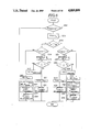
- FIG. 3 is a flowchart of a routine for deriving and setting a fuel injection pulse width representative of a fuel injection amount
- FIG. 4 is a block diagram of an input/output unit in the control unit to be employed in the preferred embodiment of the air/fuel ratio control system of FIG. 2;
- FIG. 5 is a flowchart of a routine for discriminating engine operating condition for governing control operation mode between FEEDBACK control mode and OPEN LOOP control mode;
- FIG. 6 is a flowchart of a routine for deriving feedback correction coefficient composed of a proportional component and an integral component
- FIG. 7 is a flowchart of a learning governing routine for governing learning of K ALT and K MAP ;
- FIG. 8 is a flowchart of a K ALT learning routine for updating a map storing an air density dependent uniform correction coefficients
- FIG. 9 is a flowchart showing a K MAP learning routine for updating an engine driving range based correction coefficients
- FIG. 10 is a timing chart showing operation of the preferred embodiment of the air/fuel ratio control system of the invention.
- FIG. 11 is a flowchart of an automatically modifying routine for K ALT for modifying the K ALT automatically;
- FIG. 12 is a chart showing FEEDBACK control range which is defined in terms of engine speed N and engine load Tp;
- FIG. 13 is a chart showing range to perform learning of K ALT which is defined by throttle angular position ⁇ th , intake air flow rate Q and engine speed N;
- FIGS. 14 and 15 are flowcharts showing a sequence of K MAP learning routine as modification of the routine of FIG. 8.
- FIGS. 1 and 2 the preferred embodiment of an air/fuel ratio control system, according to the invention, is applied to a fuel injection internal combustion engine which is generally represented by the reference numeral "1".
- the engine 1 has an air induction system including an air cleaner 2, a throttle body 3 and an intake manifold 4.
- a throttle valve 5 is disposed within the throttle body 3 for adjusting induction rate of an air/fuel mixture.
- a fuel injection valve 6 is disposed within the throttle body 3 and upstream of the throttle valve 5. Therefore, the air/fuel mixture is formed at the position in the induction system upstream of the throttle valve.
- the air/fuel mixture flows through the throttle body 3 and introduced into an engine combustion chamber via the intake manifold 4 and an intake port which is open and closed by means of an intake valve.
- the air/fuel mixture introduced into the engine combustion chamber is combustioned by spark ignition taken place by means of an ignition plug 7 which receives an ignition power from an ignition coil unit 8 via a distributor 9.
- the engine 1 also has an exhaust system including an exhaust manifold 10, an exhaust duct 11, a catalytic converter unit 12 and a muffler 13.
- a throttle angle sensor 15 is associated with the throttle valve 5 to produce a throttle angle indicative signal ⁇ th having a value indicative of the monitored throttle angle.
- the throttle angle sensor 15 comprises a potentiometer producing analog form throttle angle indicative signal having a voltage variable depending upon the throttle valve angular position.
- an engine idling condition detector switch 16 is associated with the throttle valve 5 for detecting fully closed or approximately fully closed position of the throttle valve. The engine idling condition detector switch 16 outputs an engine idling condition indicative signal IDL which is held LOW level while the throttle valve 5 is not in fully closed or approximately fully closed position and is held HIGH level while the throttle valve is maintained at fully closed or approximately fully closed position.
- a crank angle sensor 17 is coupled with the distributor 9 for monitoring a crank shaft angular position.
- the crank angle sensor 17 has a rotary disc which is so designed as to rotate synchroneously with rotation of a rotor of the distributor.
- the crank angle sensor 17 produces a crank reference signal ⁇ ref at each of predetermined angular position and a crank position signal ⁇ pos at every time of predetermined angle of angular displacement of the crank shaft.
- the crank reference signal is generated every time the crank shaft is rotated at an angular position corresponding on 70° or 66° before top-dead-center (BTDC) in compression stroke of one of engine cylinder.
- BTDC top-dead-center
- crank reference signal ⁇ ref is produced at every 120° of the crank shaft angular displacement.
- crank position ⁇ pos is generated every given angular displacement, i.e. 1° or 2°, of the crank shaft.
- An engine coolant temperature sensor 18 is disposed within an engine cooling chamber to monitor a temperature of an engine coolant filled in the cooling chamber.
- the engine coolant temperature sensor 18 is designed for monitoring the temperature of the engine coolant to produce an engine coolant temperature indicative signal Tw.
- the engine coolant temperature sensor 18 produces an analog form signal having a voltage variable depending upon the engine coolant temperature condition.
- a vehicle speed sensor 19 monitors a vehicle speed for producing a vehicle speed indicative signal Vs.
- the shown embodiment of the air/fuel ratio control system includes an oxygen sensor 20 disposed in the exhaust manifold 10.
- the oxygen sensor 20 monitors oxygen concentration contained in the exhaust gas to produce an oxygen concentration indicative signal V ox indicative of the monitored oxygen concentration.
- the oxygen concentration indicative signal V ox is a voltage signal variable of the voltage depending upon the oxygen concentration.
- the voltage of the oxygen concentration indicative signal varies across a zero voltage depending on rich and lean of the air/fuel ratio relative to a stoichiometric value.
- the preferred embodiment of the air/fuel ratio control system has a control unit 100 which comprises a microprocessor.
- the control unit 100 is connected to a vehicular battery 21 to receive power supply therefrom.
- An ignition switch 22 is interposed between the control unit 100 and the vehicular battery 21 to establish and block power supply.
- the control unit 100 comprises CPU 102, RAM 104, ROM 106 and an input/output unit 108.
- the input/output unit 108 has an analog-to-digital converter 110 for converting analog inputs, such as the throttle angle indicative signal ⁇ th , the engine coolant temperature indicative signal Tw and so forth, into digital signals.
- the control unit 100 receives the throttle angle indicative signal ⁇ th , the engine idling position indicative signal IDL, the crank reference signal ⁇ ref , the crank position signal ⁇ pos , the engine coolant temperature indicative signal Tw, the vehicle speed indicative signal Vs and oxygen concentration indicative signal V ox .
- the control unit 100 derives an engine revolution speed data N on the basis of a period of the crank reference signal ⁇ pos .
- the period of the crank reference signal ⁇ ref is inversely proportional to the engine speed
- the engine speed data N can be derived from reciprocal of the period of the crank reference signal ⁇ re .
- the control unit 100 projects an intake air flow amount indicative data Q on the basis of the throttle angle position indicative signal value ⁇ th .
- the shown embodiment projects the intake air flow rate indicative data Q based on the throttle angle position indicative signal, it is, of course, possible to obtain the air flow rate indicative data Q directly by a known air flow meter.
- the intake air flow rate indicative data may also be obtained from intake vaccum pressure which may be monitored by a vaccum sensor to be disposed within the induction system.
- the control unit 100 derives a basic fuel injection amount or a basic fuel injection pulse width Tp on the basis of the engine speed data N and the intake air flow rate indicative data Q which serves to represents an engine load.
- the basic fuel injection amount Tp is corrected by a correction factors derived on the basis of the engine coolant temperature Tw, the rich/lean mixture ratio indicative oxygen concentration indicative signal V ox of the oxygen sensor 20, a battery voltage and so forth, and an enrichment factor, such as engine start up enrichment factor, acceleration enrichment factor.
- the fuel injection amount modified with the correction factors and enrichment factors set forth above, is further corrected by a air/fuel ratio dependent correction coefficient derived on the basis of the oxygen concentration indicative signal V ox for adjusting the air/fuel ratio toward the stoichiometric value.
- control unit 100 of the preferred embodiment of the air/fuel ratio control system according to the invention will be discussed herebelow with reference to FIGS. 3 to 9.
- components of the control unit 100 which are not discussed in the preceding disclosure will be discussed with the functions thereof.
- FIG. 3 shows a flowchart of a fuel injection pulse setting routine for setting a fuel injection pulse width Ti in the input/output unit 108 of the control unit 100.
- the fuel injection pulse width Ti setting routine may be triggered at every given timing for updating fuel injection pulse width data Ti in the input/output unit 108.
- the throttle angle indicative signal value ⁇ th and the engine speed data N are read out.
- search is performed against an intake air flow rate map stored in a memory block 130 of ROM 104 to project an intake air flow rate indicative data Q, which map will be hereafter referred to as "Q map", at a step 1004.
- the Q map contains various intake flow rate indicative data Q, each of which data is accessible in terms of the throttle angle indicative signal value ⁇ th and the engine speed data N.
- Each of the intake air flow rate indicative data Q is determined through experimentation. Relationship between the throttle angle indicative data ⁇ th , the engine speed data N and the intake air flow rate Q is as shown in the block representing the step 1004.
- the basic fuel injection amount Tp is derived at a step 1006.
- the basic fuel injection amount Tp can be calculated by the following equation:
- correction coefficients COEF is set.
- the correction coefficient COEF to be set here is constituted by an engine coolant temperature dependent component which will be hereafter referred to as "Tw correction coefficient", an engine start-up acceleration enrichment component which will be hereafter referred to as “start-up enrichment correction coefficient”, an acceleration enrichment component which will be hereafter referred to as “acceleration enrichment correction coefficient” and so forth.
- the Tw correction coefficient may be derived on the basis of the engine coolant temperature indicative signal Tw.
- the start-up enrichment correction coefficient may be derived in response to the ignition switch operated to a cranking position.
- the acceleration enrichment correction coefficient can be derived in response to an acceleration demand which may be detected from variation of the throttle angle indicative signal values. Manner of derivation of these correction coefficients are per se well known and unnecessary to be discussed in detail.
- a correction coefficient K ALT is read out.
- the correction coefficient K ALT is stored in a given address of memory block 131 in RAM 106 and continuously updated through learning process. This correction coefficient will be applicable for air/fuel ratio control for maintaining the air/fuel ratio of the air/fuel mixture at a stoichiometric value at any engine driving range. Therefore, the correction coefficient K ALT will be hereafter referred to as "air density dependent uniform correction coefficient”. Furthermore, address of the memory block 131 storing the air density dependent uniform correction coefficient K ALT will be hereafter referred to as "K ALT address”. At the initial stage before learning, the air density dependent uniform correction coefficient K ALT is set at a value "0".
- a correction coefficient K MAP is determined by map search in terms of the engine speed indicative data N and the basic fuel injection amount Tp, at a step 1012.
- the engine speed indicative data N and the basic fuel injection amount Tp are used as parameters identifying the engine driving range.
- a map containing a plurality of mutually distinct correction coefficients K MAP is stored in a block 132 RAM 106. This map will be hereafter referred to as "K MAP map”.
- the K MAP map storing memory block 132 is constituted by a plurality of memory addresses each storing individual correction coefficient K MAP .
- Each memory block storing individual correction coefficient K MAP is identified by known address which will be hereafter referred to as "K MAP address”.
- the K MAP address to be accessed is identified in terms of the engine speed indicative data N and the basic fuel injection amount Tp.
- the correction coefficient K MAP stored in each K MAP address is determined in relation to the engine driving range defined by the engine speed data N and the fuel injection amount Tp and continuously updated through learning process.
- this correction coefficient K MAp will be hereafter referred to as "driving range based learned correction coefficient".
- the K MAP map is formed by setting the engine speed data N in x-axis and the basic fuel injection amount Tp in y-axis.
- the x-axis component is divided into a given number n N of engine speed ranges.
- the y-axis component is divided into a given number n Tp of basic fuel injection ranges. Therefore, the K MAP map is provided (n N ⁇ n Tp ) addresses.
- the x-axis component and y-axis component are divided into 8 ranges respectively. Therefore, 64 (8 ⁇ 8) addresses are formed to store the driving range based learned correction coefficient respectively.
- each K MAP address in the K MAP initially stores a value "0" before learning process is initiated.
- a feedback correction coefficient K LAMBDA is read out. Process of derivation of the feedback correction coefficient K LAMBDA will be discussed later with reference to FIG. 6.
- a battery voltage dependent correction value Ts is set in relation to a voltage of the vehicular battery 21.
- a fuel injection amount Ti is calculated at a step 1018 according to the following equation:
- FIG. 4 shows one example of construction of part of the input/output unit 108 which is used for controlling fuel injection timing and fuel injection amount according to the set Ti data.
- FIG. 4 shows detailed construction of the relevant section of the input/output unit 108.
- the input/output unit 108 has a fuel injection start timing control section 124.
- the fuel injection start timing control section 124 has an angle (ANG) register 121, to which a fuel injection start timing derived by CPU during process of fuel injection control data, e.g. the air flow rate, throttle angle position, the engine speed and so forth.
- the fuel injection start timing control section 124 also has a crank position signal counter 122.
- the crank position signal counter 122 is designed to count up the crank position signals ⁇ pos and to be reset in response to the crank reference signal ⁇ ref .
- a comparator 123 is also provided in the fuel injection start timing control section 124.
- the comparator 123 compares the fuel injection start timing indicative value set in the ANG register 121 and the crank position signal counter value in the counter 122.
- the comparator 123 outputs HIGH level comparator signal when the crank position signal counter value becomes the same as that of the fuel injection start timing indicative value.
- the HIGH level comparator signal of the comparator 123 is fed to a fuel injection pulse output section 127.
- the fuel injection pulse output section 130 has a fuel injection pulse generator 127a.
- the fuel injection pulse generator 127a comprises a fuel injection (EGI) register 125, a clock counter 126, a comparator 128 and a power transistor 129.
- a fuel injection pulse width data which is determined through data processing during execution of fuel injection control program to be discussed later, is set in the EGI register 125.
- the output of the comparator 123 is connected to the clock counter 126.
- the clock counter 126 is responsive to the leading edge of HIGH level output of the comparator to be reset.
- the clock counter 126 is connected to a clock generator 112 in the control unit 100 to receive therefrom a clock pulse.
- the clock counter 126 counts up the clock pulse as triggered by the HIGH level gate signal.
- the comparator 128 is triggered in response to resetting of the clock counter 126 to output HIGH level comparator signal to the base electrode of the power transistor 129.
- the power transistor 129 is thus turned ON to open the fuel injection valve 6 to perform fuel injection.
- the comparator signal of the comparator 128 turns into LOW level to turn OFF the power transistor 129.
- the fuel injection valve 4 closes to terminate fuel injection.
- the ANG register 121 in the fuel injection start timing control section 124 updates the set fuel injection start timing data at every occurrence of the crank reference signal ⁇ ref .
- fuel injection starts at the timing set in the ANG register 121 and is maintained for a period as set in the EGI register 125.
- the fuel injection amount can be controlled by adjusting the fuel injection pulse width.
- FIG. 5 shows a routine governing control mode to switch the mode between FEEDBACK control mode and OPEN LOOP control mode based on the engine driving condition.
- FEEDBACK control of air/fuel ratio is taken place while the engine is driven under load load and at low speed and OPEN LOOP control is performed otherwise.
- the basic fuel injection amount Tp is taken as a parameter for detecting the engine driving condition.
- a map containing FEEDBACK condition indicative criteria Tp ref is set in a memory block 133 of ROM 104. The map is designed to be searched in terms of the engine speed N, at a step 1102.
- the FEEDBACK condition indicative criteria set in the map are experimentarily obtained and define the engine driving range to perform FEEDBACK control, which engine driving range is explanatorily shown by the hatched area of the map illustrated within the process block 1102 of FIG. 5.
- the basic fuel injection amount Tp derived in the process of the step 1006 is then compared with the FEEDBACK condition indicative criterion Tp ref , at a step 1104.
- a delay timer 134 in the control unit 100 and connected to a clock generator 135, is reset to clear a delay timer value t DELAY , at a step 1106.
- the delay timer value t DELAY is read and compared with a timer reference value t ref , at a step 1108. If the delay timer value t DELAY is smaller than or equal to the timer reference value t ref , the engine speed data N is read and compared with an engine speed reference N ref , at a step 1110.
- the engine speed reference N ref represents the engine speed criterion between high engine speed range and low engine speed range. Practically, the engine speed reference N ref is set at a value corresponding to a high/low engine speed criteria, e.g. 3800 r.p.m.
- a FEEDBACK condition indicative flag FL FEEDBACK which is to be set in a flag register 136 in the control unit 100, is set at a step 1112.
- a FEEDBACK condition indicative flag FL FEEDBACK is reset, at a step 1114. After one of the step 1112 and 1114, process goes END and is returned to a background job which governs execution of various routines.
- FEEDBACK control can be maintained for the period of time corresponding to the period defined by the timer reference value. This expands period to perform FEEDBACK control and to perform learning.
- FEEDBACK control can be maintained for the given period corresponding to the set delay time to learning of correction coefficient for adapting the air/fuel ratio to the air density even though the engine driving condition is in transition state.
- FIG. 6 shows a routine for deriving the feedback correction coefficient K LAMBDA .
- the feedback correction coefficient K LAMBDA is composed of a proportional (P) component and an integral (I) component.
- the shown routine is triggered every given timing, i.e. every 10 ms., in order to regularly update the feedback control coefficient K LAMBDA .
- the feedback control coefficient K LAMBDA is stored in a memory block 137 and cyclically updated during a period in which FEEDBACK control is performed.
- the FEEDBACK condition indicative flag FL FEEDBACK is checked.
- the FEEDBACK condition indicative flag FL FEEDBACK is not set as checked at the step 1202, which indicates that the on-going control mode is OPEN LOOP. Therefore, process directly goes END.
- the feedback correction coefficient K LAMBDA is not updated, the content in the memory block 137 storing the feedback correction coefficient is held in unchanged.
- the oxygen concentration indicative signal V ox from the oxygen sensor 20 is read out at a step 1204.
- the oxygen concentration indicative signal value V ox is then compared with a predetermined rich/lean criterion V ref which corresponding to the air/fuel ratio of stoichiometric value, at a step 1206.
- a lean mixture indicative flag FL LEAN which is set in a lean mixture indicative flag register 138 in the control unit 100, is checked at a step 1208.
- the feedback correction coefficient K LAMBDA is updated by adding a given integral constant (I constant), at a step 1216.
- a faulty sensor indicative flag FL ABNORMAL is set in a flag register 156 at a step 1218. After setting the faulty sensor indicative flag FL ABNORMAL process goes END.
- an rich/lean inversion indicative flag FL INV which is set in a flag register 139 in the control unit 100, is set at a step 1220.
- a rich mixture indicative flag FL RICH which is set in a flag register 139, is reset and the lean mixture indicative flag FL LEAN is set, at a step 1222.
- the faulty timer value C in the faulty sensor detecting timer 148 is reset and the faulty sensor indicative flag FL ABNORMAL is reset, at a step 1224.
- the feedback correction coefficient K LAMBDA is modified by adding a proportional constant (P constant), at a step 1226.
- the counter value C of the faulty sensor detecting timer 148 in the control unit 100 is incremented by one (1), at a step 1230.
- the faulty timer value C is compared with the preset faulty timer criterion C 0 , at a step 1232.
- the rich/lean inversion indicative flag FL INV is reset at a step 1234.
- the feedback correction coefficient K LAMBDA is updated by subtracting the I constant, at a step 1236.
- a faulty sensor indicative flag FL ABNORMAL is set at a step 1238. After setting the faulty sensor indicative flag FL ABNORMAL process goes END.
- an rich/lean inversion indicative flag FL INV which is set in a flag register 139 in the control unit 100, is set at a step 1240.
- a rich mixture indicative flag FL LEAN is reset and the rich mixture indicative flag FL RICH is set, at a step 1242.
- the faulty timer value C in the faulty sensor detecting timer 148 is reset and the faulty sensor indicative flag FL ABNORMAL is reset, at a step 1244.
- the feedback correction coefficient K LAMBDA is modified by subtracting the P constant, at a step 1246.
- process goes to the END.
- the P component is set at a value far greater than that of I component.
- FIG. 7 shows a learning governing routine for selectively updating air density dependent uniform correction coefficient K ALT and the driving range based learned correction coefficient K MAP . Since learning of the correction coefficients K ALT and K MAP can be performed only when the FEEDBACK control is performed.
- the FEEDBACK condition indicative flag FL FEEDBACK is checked at a step 1302. When the FEEDBACK condition indicative flag FL FEEDBACK is not set as checked at the step 1302, a K ALT learning cycle counter value C ALT in a K ALT counter 149 in RAM 106 and a K MAP learning cycle counter value C MAP in a K MAP counter 142 are cleared at a step 1304 and thereafter process goes END.
- a throttle angle reference value ⁇ th ref is derived on the basis of the engine speed data N, at a step 1306.
- the throttle angle reference value ⁇ th ref is set in a form of a table data to be read in terms of the engine speed N.
- Each value of the throttle angle reference value ⁇ th ref is representative of high engine load condition criteria at respective engine speed range, above which the intake air flow rate Q is held unchanged. Namely, when the throttle angle position ⁇ th is greater than or equal to the throttle angle reference value ⁇ th ref , the air flow rate is held substantially unchanged. In such engine driving condition, air density dependent uniform correction coefficient K ALT is to be updated.
- the throttle angle reference value ⁇ th ref will be hereafter referred to as "Q flat range threshold".
- the throttle angle indicative signal value ⁇ th.sub. is compared with the Q flat range threshold ⁇ th ref derived at the step 1306. If the throttle angle indicative signal value ⁇ th.sub. is greater than or equal to the Q flat range threshold ⁇ th ref , another throttle angle reference value ⁇ th inhibit is derived in terms of the engine speed data N at a step 1310.
- the throttle angle reference value ⁇ th inhibit represents substantially high engine load range where flow velocity of the intake is lowered to make distribution of the air/fuel mixture worse. This may cause substantial fluctuation of the air/fuel ratio to cause significant variation of the oxygen concentration indicative signal value V ox .
- the throttle angle indicative signal value ⁇ th is compared with the learning inhibiting threshold ⁇ th inhibit .
- the throttle angle indicative signal value ⁇ th is smaller than or equal to the learning inhibiting threshold ⁇ th inhibit
- check is performed whether a timer value t ACC of a timer 150 in the control unit 100 is greater than or equal to a timer reference value t enable , at a step 1314.
- the timer reference value t enable represents possible maximum period required after recovery of stability after rapid acceleration. Namely, during rapid acceleration, part of the fuel injection through the fuel injection valve 6 flows on the inner periphery of the induction passage to influence of stability of the air/fuel ratio. This peripheral flow of the fuel may be maintained even after termination of the engine acceleration. Therefore, in order to avoid influence of unstability of the air/fuel radio during the engine acceleration period and subsequent period required for stabilization, it is better not to perform learning of the air density dependent uniform correction coefficient K ALT .
- the K MAP learning cycle counter value C MAP is cleared at the step 1316. Then, at a step 1318, K ALT learning sub-routine of FIG. 8 is triggered.
- FIG. 8 shows the K ALT learning sub-routine to be triggered at the step 1318 of the learning governing routine of FIG. 7.
- K ALT learning is performed in the hatched area which is defined by the throttle angular position ⁇ th , the intake air flow rate Q and the engine speed.
- the air density dependent uniform correction coefficient K ALT is updated every occurrence of inversion of polarity of the oxygen concentration indicative signal V ox . Therefore, immediately after execution of the sub-routine of FIG. 8, the rich/lean inversion indicative flag FL INV which is set and reset through the steps 1214, 1220, 1234 and 1244 of the routine of FIG.
- step 1402 is checked, at a step 1402, so as to detect whether inversion of the rich/lean of the air/fuel mixture occurs or not.
- an updating indicative flag FL UPDATE to be set in a flag register 155 of the control unit 100, is reset, at a step 1404. Thereafter, the process directly goes END and returns to the background job.
- the K ALT learning cycle counter value C ALT is incremented by one (1) at a step 1406. Then, the K ALT learning cycle counter value C ALT is checked at a step 1408.
- process goes to the step 1404 to reset the updating indicative flag FL UPDATE . Thereafter, process goes END.
- This is required for obtaining reliable air density dependent uniform correction coefficient K ALT by deriving the coefficient based on a greater number of the feedback correction coefficient K LAMBDA .
- a first correction coefficient error value ELAMBDA 1 is derived at a step 1410.
- the first correction coefficient error value ELAMBDA 1 represents a difference between the feedback correction coefficient K LAMBDA and a coefficient reference value LAMBDA ref , e.g. 1, and is temporarily stored in a memory block 143 of RAM 106. After this the updating flag FL UPDATE is reset at a step 1412. Thereafter, process goes END.
- first and second correction coefficient error value ELAMBDA 1 and ELAMBDA 2 represents upper and lower peaks of difference of the feedback correction coefficient K LAMBDA and the reference value, which peak values appear at zero-crossing of the the oxygen concentration indicative signal value V ox .
- the second correction coefficient error value ELAMBDA 2 is derived on the basis of the instantaneous feedback correction coefficient K LAMBDA and the coefficient reference value LAMBDA ref , at a step 1412.
- An average value LAMBDA ave of the first and second correction coefficient error values ELAMBDA 1 and ELAMBDA 2 is then calculated at a step 1416.
- the relevant air density dependent uniform correction coefficient K ALT is read in terms of the engine speed data N and the basic fuel injection value Tp. Based on the average value LAMBDA ave derived at the step 1416, read relevant air density dependent uniform correction coefficient K ALT as read at the step 1418, is modified, at a step 1420. Modification of the engine driving range based correction coefficient K ALT is performed by:
- K ALT ' is a modified correction coefficient
- M ALT is a constant determining the correction coefficient K ALT modification rate, which is set in a value range of 0 ⁇ M ALT ⁇ 1.
- the modified correction coefficient K ALT ' is temporarily stored in a temporary register 144.
- the updating indicative flag FL UPDATE is set at a step 1422 and the second correction coefficient error value ELAMBDA 2 is set in the memory block 143 as the first correction coefficient error value ELAMBDA 1 for next cycle of execution, at a step 1424.
- K ALT learning counter value L KALT in a K ALT learning counter 151 in RAM 106 is incremented by 1, at a step 1426. After the step 1426, process goes END.
- updating of the correction coefficient K ALT in the K ALT map is performed only when the learning routine is repeated four cycles or more under substantially the same engine driving condition in the same engine driving range.
- FIG. 9 shows a process for learning the engine driving range based learnt correction coefficient K MAP .
- learning of the correction coefficient is performed only when the control mode is FEEDBACK mode. Therefore, at a step 1502, check is performed whether the FEEDBACK condition indicative flag FL FEEDBACK is set or not. If the FEEDBACK condition indicative flag FL FEEDBACK is set as checked at the step 1502, check is performed whether the engine speed data N and the basic fuel injection amount Tp identifies the same engine driving range as that identified in the former execution cycle, at a step 1504. In practice, check in the step 1504 is performed by comparing the address data identifying corresponding memory block in the K MAP map.
- the address data identified by the engine speed data N and the basic fuel injection amount Tp is temporarily stored in a memory block 141 of RAM 106.
- FEEDBACK condition indicative flag FL FEEDBACK is not set as checked at the step 1502 or when the address data as compared at the step 1504 do no match with the address data stored in the memory block 141 which means that the engine speed data N and the basic fuel injection amount Tp identifies different engine driving range than that identified in the former execution cycle
- an updating counter 142 in the control unit 100 is reset to clear the K MAP learning cycle counter value C MAP , at a step 1506.
- the updating indicative flag FL UPDATE is reset.
- the inversion indicative flag FL INV is checked at a step 1510.
- process goes to the step 1508 to reset the updating indicative flag FL UPDATE .
- the K MAP learning cycle counter C MAP is incremented by 1, at a step 1512. After this, the K MAP learning cycle counter value C MAP is checked at a step 1514.
- This K MAP learning cycle counter C MAP serves to count up occurrence of updating of updating of the feedback correction coefficient K LAMBDA while the engine driving range is held in the one range.
- a first correction coefficient error value ELAMBDA 1 is derived at a step 1516.
- the first correction coefficient error value ELAMBDA represents a difference between the feedback correction coefficient K LAMBDA and a coefficient reference value LAMBDA ref , e.g. 1, and is temporarily stored in a memory block 143 of RAM 106. After this the updating flag FL UPDATE is reset at a step 1518.
- process goes END.
- a second correction coefficient error value ELAMBDA 2 is derived on the basis of the instantaneous feedback correction coefficient K LAMBDA and the coefficient reference value LAMBDA ref , at a step 1520.
- An average value LAMBDA ave of the first and second correction coefficient error values ELAMBDA 1 and ELAMBDA 2 is then calculated at a step 1522.
- the engine driving range based learnt correction coefficient K MAP is read in terms of the engine speed data N and the basic fuel injection value Tp.
- the K ALT learning counter value L KALT is read out from the K ALT learning counter 151 and compared with a K ALT learning threshold value LKALT ref .
- a K MAP modification rate indicative constant M MAP is set at a given first value, at a step 1528.
- a K MAP modification rate indicative constant M MAP is set at a given second value which is smaller than the first value at a step 1530.
- K MAP ' is a modified correction coefficient
- the modified correction coefficient K MAP ' is temporarily stored in a temporary register 144.
- the updating indicative flag FL UPDATE is set at a step 1534 and the second correction coefficient error value ELAMBDA 2 is set in the memory block 143 as the first correction coefficient error value ELAMBDA 1 next cycle of execution, at a step 1536.
- FIG. 11 shows a routine for automatically modifying the learnt uniform correction coefficient K ALT during engine driving at substantially high engine speed and high engine load condition.
- Such automatic modification of the air density dependent uniform correction coefficient K ALT becomes necessary when the engine is held at high speed and high load condition where FEEDBACK control is held inactive for a long period of time.
- Such engine driving condition tends to appear during hill or mountain climbing, for example.
- the faulty sensor indicative flag FL ABNORMAL is checked at a step 1602.
- a FEEDBACK OFF timer value TIM of a FEEDBACK OFF timer 152 is cleared at a step 1604. Thereafter, process goes END.
- the engine speed data N and the engine load data Tp are checked so as to check whether the engine is driven in high speed and high load condition, at a step 1606.
- distinction of the engine driving condition is performed with respect to the air/fuel ratio FEEDBACK control criteria set with respect to the engine speed N and the engine load indicative basic fuel injection amount value Tp, as shown in FIG. 12.
- the high speed and high load range is set to include part of the engine medium speed and medium load range which is possible to perform air/fuel ratio FEEDBACK control and thus is possible to perform K ALT learning during driving in high altitude area.
- the FEEDBACK OFF timer value TIM is incremented by one (1), at a step 1608. Then, the FEEDBACK OFF timer value TIM is compared with a predetermined FEEDBACK OFF timer threshold TIM ref at a step 1610. If the FEEDBACK OFF timer value TIM is smaller than the FEEDBACK OFF timer threshold TIM ref as checked at the step 1610, process goes END.
- air density dependent uniform correction coefficient can be learned even at high speed and high load engine driving condition so as to follow the air/fuel mixture ratio control to the air density at any environmental condition.
- FIGS. 14 and 15 shows a modification of the K MAP learning routine, which modification is intended to divide correction coefficient error value ELAMBDA to be used in derivation of the engine driving range based learnt correction coefficient K MAP into first altitude dependent component and second component depending on other factors in order to introduce an inference factor in air/fuel ratio control.
- FIGS. 14 and 15 there is shown a sequence of routine for learning the engine driving range based learned correction coefficient K MAP .
- learning of the correction coefficient is performed only when the control mode is FEEDBACK mode. Therefore, at a step 1702, check is performed whether the FEEDBACK condition indicative flag FL FEEDBACK is set or not. If the FEEDBACK condition indicative flag FL FEEDBACK is set as checked at the step 1702, check is performed whether the engine speed data N and the basic fuel injection amount Tp identifies the same engine driving range as that identified in the former execution cycle, at a step 1704. In practice, check in the step 1704 is performed by comparing the address data identifying corresponding memory block in the K MAP map.
- the address data identified by the engine speed data N and the basic fuel injection amount Tp is temporarily stored in a memory block 141 of RAM 106.
- FEEDBACK condition indicative flag FL FEEDBACK is not set as checked at the step 1702 or when the address data as compared at the step 1704 do no match with the address data stored in the memory block 141 which means that the engine speed data N and the basic fuel injection amount Tp identifies different engine driving range than that identified in the former execution cycle
- an updating counter 142 in the control unit 100 is reset to clear the K MAP learning cycle counter value C MAP , at a step 1706.
- the updating indicative flag FL UPDATE is reset.
- the inversion indicative flag FL INV is checked at a step 1710.
- process goes to the step 1708 to reset the updating indicative flag FL UPDATE .
- the K MAP learning cycle counter C MAP is incremented by 1, at a step 1712. After this, the K MAP learning cycle counter value C MAP is checked at a step 1714.
- This K MAP learning cycle counter C MAP serves to count up occurrence of updating of updating of the feedback correction coefficient K LAMBDA while the engine driving range is held in the one range.
- a first correction coefficient error value ELAMBDA 1 is derived at a step 1716.
- the first correction coefficient error value ELAMBDA represents a difference between the feedback correction coefficient K LAMBDA and a coefficient reference value LAMBDA ref , e.g. 1, and is temporarily stored in a memory block 143 of RAM 106. After this the updating flag FL UPDATE is reset at a step 1718.
- process goes END.
- a second correction coefficient error value ELAMBDA 2 is derived on the basis of the instantaneous feedback correction coefficient K LAMBDA and the coefficient reference value LAMBDA ref , at a step 1720.
- An average value LAMBDA ave of the first and second correction coefficient error values ELAMBDA 1 and ELAMBDA 2 is then calculated at a step 1722.
- the average value LAMBDA ave may include the first altitude dependent component and the second component depending upon other factors. Therefore, in the shown process, a ratio k of the first component versus the second component is derived through steps 1724 through 1734 which will be discussed later.
- a throttle angle dependent first component ratio indicative value k 1 is derived in terms of the throttle angle indicative signal value ⁇ th utilizing a k 1 map 153 set in ROM 104.
- This k 1 table 153 contains experimentarily obtained values, which becomes greater at greater throttle open angle range, as shown in the block of the step 1724 in FIG. 15.
- This k 1 value corresponds to a membership coefficient. Since the influence to the air/fuel ratio fluctuation of error in fuel injection amount, error in measurement of the throttle angle position, tolerance of various components and so forth is relatively great in engine low load condition, the k 1 ratio representing ratio of the first altitude dependent component versus the second component depending on the other factor is held small. Since the influence of the second component to the air/fuel ratio fluctuation becomes smaller in the engine high load range, the influence of the altitude become greater as shown.
- the shown embodiment employs the throttle angle position as a factor representing the engine load condition, it may be possible to take other equivalent factor, such as basic fuel injection amount Tp, the intake air flow rate Q. Furthermore, the k 1 value may also be derived in terms of a combination of the engine speed and the engine load.
- step 1726 number of K MAP table areas which is recently updates is checked for a given number of most recently updated areas.
- polarities of differences between previously set values and the updated values in respective of the K MAP table areas to be checked are detected. Namely, when the engine driving range based learnt correction coefficient K MAP is increased in updating, the polarity of the difference becomes position, and, on the other hand, when the the engine driving range based learned correction coefficient K MAP is decreased in updating, the polarity of the difference becomes negative.
- the area in which the positive difference is detected will be hereafter referred to as "positive difference area” and the area in which the negative difference is detected will be hereafter referred to as "negative difference area”.
- a second component ratio indicative value k 2 is derived by utilizing a k 2 map 154 in ROM 104, at a step 1728.
- the second component ratio indicative value k 2 increases according to increasing of the same difference polarity area number A 1 . Namely, during up-hill driving or down-hill driving, updating area tends to incline to one of the positive difference areas and the negative difference area.
- a third component ratio indicative value k 3 is determined at a step 1732, by utilizing k 3 map 154 set in ROM 104.
- the air/fuel ratio tends to be richer due to lower air density to cause increasing of lean-side correction coefficient. Therefore, in such high altitude region, negative polarity area tends to be increased.
- the air/fuel ratio tends to become leaner due to higher air density to require richer-side air/fuel ratio control. Therefore, in this region, positive polarity area is increased.
- the k 3 map is designed to increase the value according to increasing of the same polarity area number A 2 .
- an average component ratio value which serves as a control coefficient k is derived by obtaining average value of the first, second and third component ratio indicative values k 1 , k 2 and k 3 , at a step 1734.
- the air density dependent uniform correction coefficient K ALT is read. Based on the average value LAMBDA ave derived at the step 1722 and the control coefficient k as derived at the step 1734, data of the air density dependent uniform correction coefficient K ALT as read at the step 1736, is modified, at a step 1738. Modification of the air density dependent uniform correction coefficient K ALT is performed by:
- K ALT ' is a modified correction coefficient
- the modified correction coefficient K ALT ' is temporarily stored in a temporary register 144.
- the engine driving range based learned correction coefficient K MAP is read in terms of the engine speed data N and the basic fuel injection value Tp. Based on the average value LAMBDA ave derived at the step 1722 and the control coefficient k as derived at the step 1734, data of the engine driving range based learnt correction coefficient K MAP as read at the step 1740, is modified, at a step 1742. Modification of the engine driving range based correction coefficient K MAP is performed by:
- K MAP ' is a modified correction coefficient
- the modified correction coefficient K MAP ' is temporarily stored in a temporary register 144.
- the updating indicative flag FL UPDATE is set at a step 1744 and the second correction coefficient error value ELAMBDA 2 is set in the memory block 143 as the first correction coefficient error value ELAMDA 1 for next cycle of execution, at a step 1746.
- control feature can be introduced in learning of the air density dependent uniform correction coefficient K ALT .
- fuzzy control feature may be introduced in derivation of the air density dependent uniform correction coefficient K ALT by utilizing two of three values.
Landscapes
- Engineering & Computer Science (AREA)
- Chemical & Material Sciences (AREA)
- Combustion & Propulsion (AREA)
- Mechanical Engineering (AREA)
- General Engineering & Computer Science (AREA)
- Electrical Control Of Air Or Fuel Supplied To Internal-Combustion Engine (AREA)
Abstract
Description
Tp=K×Q/N
Ti=Tp×COEF×(K.sub.LAMBDA +K.sub.ALT +K.sub.MAP)+Ts
K.sub.ALT '=K.sub.ALT +M.sub.ALT ×LAMBDA.sub.ave
K.sub.MAP '=K.sub.MAP +M.sub.MAP ×LAMBDA.sub.ave
K.sub.ALT '=K.sub.ALT +M.sub.ALT ×LAMBDA.sub.ave ×k
K.sub.MAP '=K.sub.MAP +M.sub.MAP ×LAMBDA.sub.ave ×(1-k)
Claims (33)
Applications Claiming Priority (6)
| Application Number | Priority Date | Filing Date | Title |
|---|---|---|---|
| JP62-129893 | 1987-05-28 | ||
| JP12989387A JPS63295834A (en) | 1987-05-28 | 1987-05-28 | Air-fuel ratio learning control device for internal combustion engines |
| JP62-131826 | 1987-05-29 | ||
| JP13182687A JPS63297752A (en) | 1987-05-29 | 1987-05-29 | Learning controller for air-fuel ratio for internal combustion engine |
| JP62-148035 | 1987-06-16 | ||
| JP14803587A JPH0647960B2 (en) | 1987-06-16 | 1987-06-16 | Air-fuel ratio learning controller for internal combustion engine |
Publications (1)
| Publication Number | Publication Date |
|---|---|
| US4889099A true US4889099A (en) | 1989-12-26 |
Family
ID=27316015
Family Applications (1)
| Application Number | Title | Priority Date | Filing Date |
|---|---|---|---|
| US07/197,843 Expired - Lifetime US4889099A (en) | 1987-05-28 | 1988-05-24 | Air/fuel mixture ratio control system for internal combustion engine with feature of learning correction coefficient including altitude dependent factor |
Country Status (1)
| Country | Link |
|---|---|
| US (1) | US4889099A (en) |
Cited By (8)
| Publication number | Priority date | Publication date | Assignee | Title |
|---|---|---|---|---|
| US5033440A (en) * | 1989-06-27 | 1991-07-23 | Mitsubishi Jidosha Kogyo Kabushiki Kaisha | Apparatus for controlling air/fuel ratio of internal combustion engine |
| US5158063A (en) * | 1990-12-28 | 1992-10-27 | Honda Giken Kogyo K.K. | Air-fuel ratio control method for internal combustion engines |
| US5524599A (en) * | 1994-01-19 | 1996-06-11 | Kong, Deceased; Hakchul H. | Fuzzy logic air/fuel controller |
| US5971747A (en) * | 1996-06-21 | 1999-10-26 | Lemelson; Jerome H. | Automatically optimized combustion control |
| US6227842B1 (en) | 1998-12-30 | 2001-05-08 | Jerome H. Lemelson | Automatically optimized combustion control |
| US6468069B2 (en) | 1999-10-25 | 2002-10-22 | Jerome H. Lemelson | Automatically optimized combustion control |
| US20110077845A1 (en) * | 2009-09-29 | 2011-03-31 | Gm Global Technology Operations, Inc. | Fuel control system and method for improved response to feedback from an exhaust system |
| US20120166068A1 (en) * | 2010-12-24 | 2012-06-28 | Kawasaki Jukogyo Kabushiki Kaisha | Air-Fuel Ratio Control System and Air-Fuel Ratio Control Method of Internal Combustion Engine |
Citations (5)
| Publication number | Priority date | Publication date | Assignee | Title |
|---|---|---|---|---|
| US4753208A (en) * | 1985-11-22 | 1988-06-28 | Honda Giken Kogyo Kabushiki Kaisha | Method for controlling air/fuel ratio of fuel supply system for an internal combustion engine |
| US4761950A (en) * | 1985-09-10 | 1988-08-09 | Toyota Jidosha Kabushiki Kaisha | Double air-fuel ratio sensor system carrying out learning control operation |
| US4766870A (en) * | 1986-04-30 | 1988-08-30 | Honda Giken Kogyo Kabushiki Kaisha | Method of air/fuel ratio control for internal combustion engine |
| US4768485A (en) * | 1985-01-10 | 1988-09-06 | Atlas Fahrzeugtechnik Gmbh | Mixture control for an internal combustion engine |
| US4789939A (en) * | 1986-11-04 | 1988-12-06 | Ford Motor Company | Adaptive air fuel control using hydrocarbon variability feedback |
-
1988
- 1988-05-24 US US07/197,843 patent/US4889099A/en not_active Expired - Lifetime
Patent Citations (5)
| Publication number | Priority date | Publication date | Assignee | Title |
|---|---|---|---|---|
| US4768485A (en) * | 1985-01-10 | 1988-09-06 | Atlas Fahrzeugtechnik Gmbh | Mixture control for an internal combustion engine |
| US4761950A (en) * | 1985-09-10 | 1988-08-09 | Toyota Jidosha Kabushiki Kaisha | Double air-fuel ratio sensor system carrying out learning control operation |
| US4753208A (en) * | 1985-11-22 | 1988-06-28 | Honda Giken Kogyo Kabushiki Kaisha | Method for controlling air/fuel ratio of fuel supply system for an internal combustion engine |
| US4766870A (en) * | 1986-04-30 | 1988-08-30 | Honda Giken Kogyo Kabushiki Kaisha | Method of air/fuel ratio control for internal combustion engine |
| US4789939A (en) * | 1986-11-04 | 1988-12-06 | Ford Motor Company | Adaptive air fuel control using hydrocarbon variability feedback |
Cited By (11)
| Publication number | Priority date | Publication date | Assignee | Title |
|---|---|---|---|---|
| US5033440A (en) * | 1989-06-27 | 1991-07-23 | Mitsubishi Jidosha Kogyo Kabushiki Kaisha | Apparatus for controlling air/fuel ratio of internal combustion engine |
| US5158063A (en) * | 1990-12-28 | 1992-10-27 | Honda Giken Kogyo K.K. | Air-fuel ratio control method for internal combustion engines |
| US5524599A (en) * | 1994-01-19 | 1996-06-11 | Kong, Deceased; Hakchul H. | Fuzzy logic air/fuel controller |
| US5971747A (en) * | 1996-06-21 | 1999-10-26 | Lemelson; Jerome H. | Automatically optimized combustion control |
| US5993194A (en) * | 1996-06-21 | 1999-11-30 | Lemelson; Jerome H. | Automatically optimized combustion control |
| US6227842B1 (en) | 1998-12-30 | 2001-05-08 | Jerome H. Lemelson | Automatically optimized combustion control |
| US6468069B2 (en) | 1999-10-25 | 2002-10-22 | Jerome H. Lemelson | Automatically optimized combustion control |
| US20110077845A1 (en) * | 2009-09-29 | 2011-03-31 | Gm Global Technology Operations, Inc. | Fuel control system and method for improved response to feedback from an exhaust system |
| US8186336B2 (en) * | 2009-09-29 | 2012-05-29 | GM Global Technology Operations LLC | Fuel control system and method for improved response to feedback from an exhaust system |
| US20120166068A1 (en) * | 2010-12-24 | 2012-06-28 | Kawasaki Jukogyo Kabushiki Kaisha | Air-Fuel Ratio Control System and Air-Fuel Ratio Control Method of Internal Combustion Engine |
| US9026340B2 (en) * | 2010-12-24 | 2015-05-05 | Kawasaki Jukogyo Kabushiki Kaisha | Air-fuel ratio control system and air-fuel ratio control method of internal combustion engine |
Similar Documents
| Publication | Publication Date | Title |
|---|---|---|
| US5080064A (en) | Adaptive learning control for engine intake air flow | |
| US4676215A (en) | Method and apparatus for controlling the operating characteristic quantities of an internal combustion engine | |
| US4646697A (en) | Method and apparatus for controlling the operating characteristic quantities of an internal combustion engine | |
| US4365299A (en) | Method and apparatus for controlling air/fuel ratio in internal combustion engines | |
| US4321903A (en) | Method of feedback controlling air-fuel ratio | |
| US4467770A (en) | Method and apparatus for controlling the air-fuel ratio in an internal combustion engine | |
| US5749346A (en) | Electronic control unit for controlling an electronic injector fuel delivery system and method of controlling an electronic injector fuel delivery system | |
| US4911129A (en) | Air/fuel mixture ratio control system in internal combustion engine with _engine operation range dependent _optimum correction coefficient learning feature | |
| EP0456283B1 (en) | Control system for internal combustion engine | |
| US4889099A (en) | Air/fuel mixture ratio control system for internal combustion engine with feature of learning correction coefficient including altitude dependent factor | |
| EP0440173B1 (en) | Method and apparatus for controlling torque generated in an internal combustion engine | |
| US4884547A (en) | Air/fuel ratio control system for internal combustion engine with variable control characteristics depending upon precision level of control parameter data | |
| US4924836A (en) | Air/fuel ratio control system for internal combustion engine with correction coefficient learning feature | |
| US4957083A (en) | Fuel supply control system for internal combustion engine with feature providing engine stability in low engine load condition | |
| US5181499A (en) | Apparatus for diagnosing abnormality in fuel injection system and fuel injection control system having the apparatus | |
| EP0292973B1 (en) | Air/fuel mixture ratio control system for internal combustion engine with feature of learning correction coefficient including altitude dependent factor | |
| JPH06117291A (en) | Air-fuel ratio control device for internal combustion engine | |
| US4850326A (en) | Apparatus for learning and controlling air/fuel ratio in internal combustion engine | |
| US6536414B2 (en) | Fuel injection control system for internal combustion engine | |
| US4616618A (en) | Apparatus for metering an air-fuel mixture to an internal combustion engine | |
| US4903671A (en) | Air/fuel ratio control system for fuel injection internal combustion engine with improved acceleration characteristics after deceleration | |
| US20020174856A1 (en) | Controller for controlling an evaporated fuel amount to be purged | |
| US5080075A (en) | Acceleration enrichment related correction factor learning apparatus for internal combustion engine | |
| JP2750777B2 (en) | Electronic control fuel supply device for internal combustion engine | |
| JP3052680B2 (en) | Fuel injection control device |
Legal Events
| Date | Code | Title | Description |
|---|---|---|---|
| AS | Assignment |
Owner name: JAPAN ELECTRONIC CONTROL SYSTEMS COMPANY, LIMITED, Free format text: ASSIGNMENT OF ASSIGNORS INTEREST.;ASSIGNOR:TOMISAWA, NAOKI;REEL/FRAME:004887/0228 Effective date: 19880509 Owner name: JAPAN ELECTRONIC CONTROL SYSTEMS COMPANY, LIMITED, Free format text: ASSIGNMENT OF ASSIGNORS INTEREST;ASSIGNOR:TOMISAWA, NAOKI;REEL/FRAME:004887/0228 Effective date: 19880509 |
|
| STCF | Information on status: patent grant |
Free format text: PATENTED CASE |
|
| FEPP | Fee payment procedure |
Free format text: PAYOR NUMBER ASSIGNED (ORIGINAL EVENT CODE: ASPN); ENTITY STATUS OF PATENT OWNER: LARGE ENTITY |
|
| FPAY | Fee payment |
Year of fee payment: 4 |
|
| FPAY | Fee payment |
Year of fee payment: 8 |
|
| FPAY | Fee payment |
Year of fee payment: 12 |