EP0289770A2 - Distributeur à plusieurs voies - Google Patents
Distributeur à plusieurs voies Download PDFInfo
- Publication number
- EP0289770A2 EP0289770A2 EP88104710A EP88104710A EP0289770A2 EP 0289770 A2 EP0289770 A2 EP 0289770A2 EP 88104710 A EP88104710 A EP 88104710A EP 88104710 A EP88104710 A EP 88104710A EP 0289770 A2 EP0289770 A2 EP 0289770A2
- Authority
- EP
- European Patent Office
- Prior art keywords
- housing
- actuator
- inlet
- outlet openings
- openings
- Prior art date
- Legal status (The legal status is an assumption and is not a legal conclusion. Google has not performed a legal analysis and makes no representation as to the accuracy of the status listed.)
- Granted
Links
Images
Classifications
-
- F—MECHANICAL ENGINEERING; LIGHTING; HEATING; WEAPONS; BLASTING
- F16—ENGINEERING ELEMENTS AND UNITS; GENERAL MEASURES FOR PRODUCING AND MAINTAINING EFFECTIVE FUNCTIONING OF MACHINES OR INSTALLATIONS; THERMAL INSULATION IN GENERAL
- F16K—VALVES; TAPS; COCKS; ACTUATING-FLOATS; DEVICES FOR VENTING OR AERATING
- F16K11/00—Multiple-way valves, e.g. mixing valves; Pipe fittings incorporating such valves
- F16K11/02—Multiple-way valves, e.g. mixing valves; Pipe fittings incorporating such valves with all movable sealing faces moving as one unit
- F16K11/08—Multiple-way valves, e.g. mixing valves; Pipe fittings incorporating such valves with all movable sealing faces moving as one unit comprising only taps or cocks
- F16K11/085—Multiple-way valves, e.g. mixing valves; Pipe fittings incorporating such valves with all movable sealing faces moving as one unit comprising only taps or cocks with cylindrical plug
- F16K11/0856—Multiple-way valves, e.g. mixing valves; Pipe fittings incorporating such valves with all movable sealing faces moving as one unit comprising only taps or cocks with cylindrical plug having all the connecting conduits situated in more than one plane perpendicular to the axis of the plug
-
- F—MECHANICAL ENGINEERING; LIGHTING; HEATING; WEAPONS; BLASTING
- F16—ENGINEERING ELEMENTS AND UNITS; GENERAL MEASURES FOR PRODUCING AND MAINTAINING EFFECTIVE FUNCTIONING OF MACHINES OR INSTALLATIONS; THERMAL INSULATION IN GENERAL
- F16K—VALVES; TAPS; COCKS; ACTUATING-FLOATS; DEVICES FOR VENTING OR AERATING
- F16K11/00—Multiple-way valves, e.g. mixing valves; Pipe fittings incorporating such valves
- F16K11/02—Multiple-way valves, e.g. mixing valves; Pipe fittings incorporating such valves with all movable sealing faces moving as one unit
- F16K11/06—Multiple-way valves, e.g. mixing valves; Pipe fittings incorporating such valves with all movable sealing faces moving as one unit comprising only sliding valves, i.e. sliding closure elements
- F16K11/065—Multiple-way valves, e.g. mixing valves; Pipe fittings incorporating such valves with all movable sealing faces moving as one unit comprising only sliding valves, i.e. sliding closure elements with linearly sliding closure members
- F16K11/07—Multiple-way valves, e.g. mixing valves; Pipe fittings incorporating such valves with all movable sealing faces moving as one unit comprising only sliding valves, i.e. sliding closure elements with linearly sliding closure members with cylindrical slides
- F16K11/0716—Multiple-way valves, e.g. mixing valves; Pipe fittings incorporating such valves with all movable sealing faces moving as one unit comprising only sliding valves, i.e. sliding closure elements with linearly sliding closure members with cylindrical slides with fluid passages through the valve member
Definitions
- the invention relates to a multi-way valve, in particular for pressure-transmitting media, consisting of a housing with a multiplicity of inlet and outlet openings and an actuator which is movable in the housing and is designed as a thin-walled hollow body with devices for selectively connecting the inlet and outlet openings of the housing.
- Continuous multi-way valves are used in fluid technology to set predetermined volume flows or pressures, e.g. in handling technology, where, in addition to electric, hydraulic or pneumatic freely positionable drives are used.
- Such drives usually have a linear drive (cylinder), the displacement spaces of which are supplied with the pressure medium via continuous valves. Different lifting speeds can be achieved by supplying different volume flows. In spring-supported cylinders, a certain position is approached by applying a certain pressure. Constant valves ensure that the required pressure is maintained.
- Constant valves are generally subject to high demands with regard to the adjustment speed. Especially when using gaseous pressure media, satisfactory accuracy and load rigidity can only be achieved by quickly ventilating the displacement spaces of the drive.
- the movable slide of the known continuous valves are relatively heavy, so that high acceleration forces are necessary for rapid adjustment.
- linear slide valves have a relative Large area of attack for flow forces that always arise when throttling or redirecting flows and try to close the valve. These relatively high forces must also be applied by the electromechanical transducer.
- a valve of the type mentioned is known from DE-OS 31 49 306. It is a multi-way valve equipped with a thin-walled axial slide valve as an actuator.
- the one-piece actuator is divided into a number of cylindrical sections and flows completely around the medium to be controlled. Strong flow forces act on the annular surfaces formed by the outer surface of the actuator.
- the invention has for its object to design a multi-way valve of the type mentioned in such a way that it requires only low driving forces, so that a comparatively small electromechanical converter is able to directly, relatively large fluidic powers, i.e. to control without the interposition of a fluidic amplifier.
- This valve is designed to be simple in terms of production technology and be very quickly and continuously adjustable. It should also be small in relation to its flow rate, ie have a favorable volume utilization.
- the solution to this problem consists in the fact that the actuator is designed as a thin-walled hollow body.
- the actuator only offers the flow forces as the contact surface the small edge surfaces of the actuator openings, so that these forces are significantly lower than in known valves. Furthermore, the small total mass of the actuator results in a small moment of inertia.
- the through openings in the actuator may be known from other publications, albeit in a different context, e.g. from DE-OS 27 26 503, DE-GM 17 50 261 or DE-OS 31 26 041, but they are provided here for axial valves which have a thick-walled, divided into several chambers or at least one end, axially movable, thick-walled Have actuator which also flows only partially, but is essentially flowed around and act on the strong flow forces.
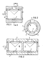
- a rotary slide valve as a 3/3-way valve. It consists of a cylindrical housing 1 with an access opening 2 and two outlet openings 3, 4 as well as a likewise cylindrical actuator 5, rotatably mounted in the housing 1, with two through openings 6, 7, which are assigned to the inlet and outlet openings 2, 3, 4 .
- the actuator 5 is designed as a very thin-walled hollow body which is closed at the end faces. 9 with a drive axis for a rotary drive is designated.
- FIG. 3 shows an embodiment of a rotary slide valve in which a plurality of inlet and outlet lines can be operated synchronously by rotating an actuator 5.
- the actuator divided into several, here two closed chambers 10, 11. Otherwise, this valve is constructed like that of FIGS. 1 and 2.
- valves of FIGS. 1 to 3 are only suitable if there are small pressure differences between the flow channels, since the pressure forces acting radially on the actuator 5 are not balanced. Higher pressure differences would therefore cause relatively high frictional forces between the actuator 5 and the housing 1.
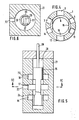
- FIG. 4 an embodiment is provided according to FIG. 4 in which inlet and outlet openings 2, 3, and 4 and 12, 13, 14 are arranged diametrically opposite one another in pairs for similar flows. Accordingly, the actuator 15 has two assigned through openings 6, 16, which connect the access openings 2, 12 each to one or the other pair of outlet openings 3, 13 or 4, 14.
- this embodiment Since no resulting compressive forces act on the actuator 15 in the radial direction in this embodiment, this embodiment is pressure-balanced. It is also suitable for high pressure differences.
- the principle of designing the actuator as a thin-walled hollow body can also be used advantageously with linear slide valves.
- Inlet and outlet openings 22, 23, 24 are provided in a housing 21.
- An actuator 25 is arranged longitudinally in the housing 21. It is shorter than the chamber 28 enclosed by the housing 21 and has two mutually opposite through openings 26, 27. These are designed as slots in the axial direction and extend so far that they enable the optional connection of the inlet and outlet openings 22, 23 and 22, 24.
- the inlet and outlet openings 22, 23 and 24 open into recesses 17, 18, 19 which surround the actuator in a ring and thus relieve pressure.
- the actuator 25 is open at its end faces. At one end it is connected to a drive rod 29 which can be actuated from outside the housing 21.
Landscapes
- Engineering & Computer Science (AREA)
- General Engineering & Computer Science (AREA)
- Mechanical Engineering (AREA)
- Multiple-Way Valves (AREA)
- Servomotors (AREA)
Applications Claiming Priority (2)
| Application Number | Priority Date | Filing Date | Title |
|---|---|---|---|
| DE19873714691 DE3714691A1 (de) | 1987-05-02 | 1987-05-02 | Mehrwegeventil |
| DE3714691 | 1987-05-02 |
Publications (3)
| Publication Number | Publication Date |
|---|---|
| EP0289770A2 true EP0289770A2 (fr) | 1988-11-09 |
| EP0289770A3 EP0289770A3 (en) | 1989-07-26 |
| EP0289770B1 EP0289770B1 (fr) | 1993-07-28 |
Family
ID=6326734
Family Applications (1)
| Application Number | Title | Priority Date | Filing Date |
|---|---|---|---|
| EP19880104710 Expired - Lifetime EP0289770B1 (fr) | 1987-05-02 | 1988-03-24 | Distributeur à plusieurs voies |
Country Status (3)
| Country | Link |
|---|---|
| EP (1) | EP0289770B1 (fr) |
| JP (1) | JPS63285303A (fr) |
| DE (1) | DE3714691A1 (fr) |
Cited By (8)
| Publication number | Priority date | Publication date | Assignee | Title |
|---|---|---|---|---|
| FR2733566A1 (fr) * | 1995-04-28 | 1996-10-31 | Vincent Eric | Vanne 2, 3 et 4 voies a autorite adaptable |
| WO2008006717A1 (fr) * | 2006-07-08 | 2008-01-17 | Schaeffler Kg | Soupape de commande hydraulique |
| WO2011015853A2 (fr) | 2009-08-01 | 2011-02-10 | Kohler Mira Limited | Systèmes de distribution de fluide |
| WO2014060100A1 (fr) * | 2012-10-19 | 2014-04-24 | Daimler Ag | Vanne à tiroir rotatif pour système de pile à combustible |
| CN106065961A (zh) * | 2016-08-04 | 2016-11-02 | 中国电力工程顾问集团中南电力设计院有限公司 | 独体旋转阀芯型汽轮机冷油器六通切换装置 |
| CN107771241A (zh) * | 2015-07-14 | 2018-03-06 | 舍弗勒技术股份两合公司 | 用于凸轮轴调节器的控制阀 |
| WO2020157612A1 (fr) * | 2019-01-28 | 2020-08-06 | Giacomini S.P.A. | Aiguillage à barillet pourvu de cartouches et d'inserts de mécanique des fluides |
| CN112587016A (zh) * | 2020-11-19 | 2021-04-02 | 慈溪市万能电子有限公司 | 一种洗漱产品杀菌消毒器具 |
Families Citing this family (15)
| Publication number | Priority date | Publication date | Assignee | Title |
|---|---|---|---|---|
| SE468188B (sv) * | 1991-04-08 | 1992-11-16 | Stiftelsen Inst Foer Mikroelek | Metod foer inkoppling av straalning i en infraroeddetektor, jaemte anordning |
| JPH0643433U (ja) * | 1992-11-17 | 1994-06-10 | 象印マホービン株式会社 | 水路切換弁 |
| ES2120076T3 (es) * | 1993-11-08 | 1998-10-16 | Sig Schweiz Industrieges | Dispositivo de mando para una bomba de regulacion del grado de llenado. |
| DE19633191C2 (de) * | 1996-08-17 | 1998-07-02 | Daimler Benz Ag | Umschaltventil für ein Druckmedium |
| JP4527410B2 (ja) * | 1999-05-13 | 2010-08-18 | 株式会社アマダ | 制御バルブ |
| JP4663844B2 (ja) * | 1999-05-13 | 2011-04-06 | 株式会社アマダ | 制御バルブ |
| DE10064671A1 (de) * | 2000-12-21 | 2002-06-27 | Behr Gmbh & Co | Ventil für eine Kraftfahrzeugheizungsanlage |
| DE10152186C1 (de) * | 2001-10-23 | 2003-06-12 | Ballard Power Systems | Brennstoffzellanlage mit einer Vorrichtung zur dosierten Zufuhr von sauerstoffhaltigem Medium an Dosierstellen eines Gaserzeugungssystems |
| DE102007009194B3 (de) * | 2007-02-26 | 2008-09-25 | Kioto Clear Energy Ag | Mehrwegeventil |
| JP5759105B2 (ja) * | 2010-01-21 | 2015-08-05 | 本田技研工業株式会社 | 油圧制御弁 |
| DE102011055902A1 (de) * | 2011-11-30 | 2013-06-06 | Jui-Yuan Cheng | Drehendes Hydraulikventil |
| DE102013101591B4 (de) * | 2013-02-18 | 2016-12-15 | Schell Gmbh & Co. Kg | Eckventil |
| DE102015201366A1 (de) * | 2015-01-27 | 2016-07-28 | Mahle International Gmbh | Ventileinrichtung, insbesondere zum Einstellen eines Kühlmittelstroms in einem Kühlsystem für eine Brennkraftmaschine eines Kraftfahrzeugs |
| JP6665799B2 (ja) * | 2017-01-23 | 2020-03-13 | トヨタ自動車株式会社 | 燃料タンクシステム |
| DE102018004082B4 (de) | 2017-05-24 | 2023-07-06 | Mann+Hummel Gmbh | Schaltventil zum Einstellen eines Fluidstroms |
Family Cites Families (16)
| Publication number | Priority date | Publication date | Assignee | Title |
|---|---|---|---|---|
| US2106572A (en) * | 1934-05-14 | 1938-01-25 | Meagher Andrew Charles | Proportioning valve |
| FR966043A (fr) * | 1948-05-05 | 1950-09-28 | Distribution à tiroir destiné à commander automatiquement les circuits chauffantset réfrigérants des générateurs utilisant comme véhicules de chaleur des liquides spéciaux | |
| GB772719A (en) * | 1953-02-25 | 1957-04-17 | Coal Industry Patents Ltd | Improvements in rotary sleeve valves |
| GB771562A (en) * | 1953-12-22 | 1957-04-03 | British Petroleum Co | Improvements in or relating to valves |
| US2898937A (en) * | 1955-02-23 | 1959-08-11 | Miehle Goss Dexter Inc | Rotary valve structure |
| GB992977A (en) * | 1961-04-08 | 1965-05-26 | Erich Kieback | Four-way valve with rotary slide |
| US3222867A (en) * | 1965-05-10 | 1965-12-14 | Hydraulic Crushers Ltd | Balanced rotary commutating valve |
| CH466954A (de) * | 1967-06-01 | 1968-12-31 | Bosch Gmbh Robert | Steuerschieber |
| DE1750261A1 (de) * | 1968-04-13 | 1971-01-28 | Krupp Gmbh | Anfahrstoss-Puffer |
| US3591135A (en) * | 1969-09-05 | 1971-07-06 | Oren E Miller | Form of gate valve |
| FR2228999B1 (fr) * | 1973-05-11 | 1976-04-23 | Bennes Marrel | |
| DE2726503A1 (de) * | 1977-06-11 | 1978-12-21 | Bosch Gmbh Robert | Steuerschieber fuer ein hydraulisches wegeventil |
| US4145958A (en) * | 1977-12-02 | 1979-03-27 | Borg-Warner Corporation | Fluid control system with automatically actuated motor port lock-out valves |
| DE2808447A1 (de) * | 1978-02-28 | 1979-08-30 | Hemscheidt Maschf Hermann | Druckausgeglichenes ventil fuer hsa-fluessigkeiten |
| DE3126041C2 (de) * | 1981-07-02 | 1985-11-28 | Danfoss A/S, Nordborg | Hydraulische Steuervorrichtung mit einer verstellbaren Drossel |
| DE3149306A1 (de) * | 1981-12-12 | 1983-06-23 | Wabco Steuerungstechnik GmbH & Co, 3000 Hannover | Wegeventil |
-
1987
- 1987-05-02 DE DE19873714691 patent/DE3714691A1/de active Granted
-
1988
- 1988-03-24 EP EP19880104710 patent/EP0289770B1/fr not_active Expired - Lifetime
- 1988-04-28 JP JP10436488A patent/JPS63285303A/ja active Pending
Cited By (17)
| Publication number | Priority date | Publication date | Assignee | Title |
|---|---|---|---|---|
| FR2733566A1 (fr) * | 1995-04-28 | 1996-10-31 | Vincent Eric | Vanne 2, 3 et 4 voies a autorite adaptable |
| WO2008006717A1 (fr) * | 2006-07-08 | 2008-01-17 | Schaeffler Kg | Soupape de commande hydraulique |
| CN102667275B (zh) * | 2009-08-01 | 2014-06-25 | 柯勒米拉有限公司 | 洗浴流体输送系统 |
| US8939175B2 (en) | 2009-08-01 | 2015-01-27 | Kohler Mira Limited | Fluid delivery systems |
| GB2484882A (en) * | 2009-08-01 | 2012-04-25 | Kohler Mira Ltd | Fluid delivery system |
| CN102667275A (zh) * | 2009-08-01 | 2012-09-12 | 柯勒米拉有限公司 | 流体输送系统 |
| GB2484882B (en) * | 2009-08-01 | 2014-01-01 | Kohler Mira Ltd | Fluid delivery systems |
| WO2011015853A3 (fr) * | 2009-08-01 | 2011-04-07 | Kohler Mira Limited | Systèmes de distribution de fluide |
| WO2011015853A2 (fr) | 2009-08-01 | 2011-02-10 | Kohler Mira Limited | Systèmes de distribution de fluide |
| WO2014060100A1 (fr) * | 2012-10-19 | 2014-04-24 | Daimler Ag | Vanne à tiroir rotatif pour système de pile à combustible |
| CN107771241A (zh) * | 2015-07-14 | 2018-03-06 | 舍弗勒技术股份两合公司 | 用于凸轮轴调节器的控制阀 |
| CN107771241B (zh) * | 2015-07-14 | 2020-11-03 | 舍弗勒技术股份两合公司 | 用于凸轮轴调节器的控制阀 |
| CN106065961A (zh) * | 2016-08-04 | 2016-11-02 | 中国电力工程顾问集团中南电力设计院有限公司 | 独体旋转阀芯型汽轮机冷油器六通切换装置 |
| WO2020157612A1 (fr) * | 2019-01-28 | 2020-08-06 | Giacomini S.P.A. | Aiguillage à barillet pourvu de cartouches et d'inserts de mécanique des fluides |
| US12013042B2 (en) | 2019-01-28 | 2024-06-18 | Giacomini S.P.A. | Multiway valve with cartridge and fluid mechanics inserts |
| CN112587016A (zh) * | 2020-11-19 | 2021-04-02 | 慈溪市万能电子有限公司 | 一种洗漱产品杀菌消毒器具 |
| CN112587016B (zh) * | 2020-11-19 | 2023-04-07 | 慈溪市万能电子有限公司 | 一种洗漱产品杀菌消毒器具 |
Also Published As
| Publication number | Publication date |
|---|---|
| EP0289770B1 (fr) | 1993-07-28 |
| DE3714691A1 (de) | 1988-12-01 |
| JPS63285303A (ja) | 1988-11-22 |
| DE3714691C2 (fr) | 1993-03-11 |
| EP0289770A3 (en) | 1989-07-26 |
Similar Documents
| Publication | Publication Date | Title |
|---|---|---|
| EP0289770B1 (fr) | Distributeur à plusieurs voies | |
| DE1575576C3 (de) | Steuerdrossel für die Zufuhr von Druckflüssigkeit | |
| DE112007003035T5 (de) | Mikroventilvorrichtung | |
| DE2559693C2 (de) | Hydraulische Nachlaufsteuerung | |
| DE1285819B (de) | Mehrfachsteuerventil | |
| EP0688411B1 (fr) | Soupape de commande hydraulique | |
| DE1959764B2 (de) | Druckkompensiertes steuerventil fuer hydraulische anlagen | |
| EP1078167B1 (fr) | Microsoupape | |
| DE3119101C2 (fr) | ||
| DE2153989C2 (de) | Hydrostatische oder aerostatische Lageranordnung | |
| DE1802626A1 (de) | Servo-Steuer-Ventil | |
| EP0238782B1 (fr) | Unité de vanne à 5/3 voies | |
| DE2343662A1 (de) | Hydraulische steuereinrichtung | |
| DE8803957U1 (de) | Mehrwegeventil | |
| EP0145859A2 (fr) | Dispositif de soupape avec organe de commande piézo-électrique ou magnéto-strictif | |
| DE2915096A1 (de) | Wegesteuerventil | |
| DE3533037C1 (de) | In die Lagerflüssigkeits-Zuleitung zur Lagertasche einer hydrostatischen Lagerung oder Führung einschaltbarer Regler | |
| EP0233500B1 (fr) | Actionneur entraîné par fluide sous pression | |
| DE19757157C2 (de) | Hydraulischer Linearantrieb | |
| DE3106532C2 (fr) | ||
| DE10164256A1 (de) | Vorrichtung zur Steuerung von Blasluft | |
| DE1262777B (de) | Hydraulischer Verstaerker, insbesondere hydraulisch kraftverstaerkter Stellantrieb | |
| DE3006298A1 (de) | Elektrisch angesteuertes ventil, insbesondere vorsteuerventil fuer logistoren | |
| DE2209394C3 (de) | Umsteuerventil mit mehreren Ventildurchgängen | |
| EP2128454A1 (fr) | Valve proportionnelle dotée de moyens de commande précise |
Legal Events
| Date | Code | Title | Description |
|---|---|---|---|
| PUAI | Public reference made under article 153(3) epc to a published international application that has entered the european phase |
Free format text: ORIGINAL CODE: 0009012 |
|
| AK | Designated contracting states |
Kind code of ref document: A2 Designated state(s): BE CH FR GB IT LI NL SE |
|
| PUAL | Search report despatched |
Free format text: ORIGINAL CODE: 0009013 |
|
| AK | Designated contracting states |
Kind code of ref document: A3 Designated state(s): BE CH FR GB IT LI NL SE |
|
| 17P | Request for examination filed |
Effective date: 19900316 |
|
| 17Q | First examination report despatched |
Effective date: 19910610 |
|
| GRAA | (expected) grant |
Free format text: ORIGINAL CODE: 0009210 |
|
| AK | Designated contracting states |
Kind code of ref document: B1 Designated state(s): BE CH FR GB IT LI NL SE |
|
| PG25 | Lapsed in a contracting state [announced via postgrant information from national office to epo] |
Ref country code: BE Effective date: 19930728 |
|
| ET | Fr: translation filed | ||
| ITF | It: translation for a ep patent filed | ||
| GBT | Gb: translation of ep patent filed (gb section 77(6)(a)/1977) |
Effective date: 19931102 |
|
| PG25 | Lapsed in a contracting state [announced via postgrant information from national office to epo] |
Ref country code: SE Free format text: LAPSE BECAUSE OF NON-PAYMENT OF DUE FEES Effective date: 19940325 |
|
| PLBE | No opposition filed within time limit |
Free format text: ORIGINAL CODE: 0009261 |
|
| STAA | Information on the status of an ep patent application or granted ep patent |
Free format text: STATUS: NO OPPOSITION FILED WITHIN TIME LIMIT |
|
| 26N | No opposition filed | ||
| EUG | Se: european patent has lapsed |
Ref document number: 88104710.4 Effective date: 19941010 |
|
| PGFP | Annual fee paid to national office [announced via postgrant information from national office to epo] |
Ref country code: GB Payment date: 19950313 Year of fee payment: 8 |
|
| PGFP | Annual fee paid to national office [announced via postgrant information from national office to epo] |
Ref country code: CH Payment date: 19950330 Year of fee payment: 8 |
|
| PGFP | Annual fee paid to national office [announced via postgrant information from national office to epo] |
Ref country code: NL Payment date: 19950331 Year of fee payment: 8 |
|
| PG25 | Lapsed in a contracting state [announced via postgrant information from national office to epo] |
Ref country code: GB Effective date: 19960324 |
|
| PG25 | Lapsed in a contracting state [announced via postgrant information from national office to epo] |
Ref country code: LI Effective date: 19960331 Ref country code: CH Effective date: 19960331 |
|
| PG25 | Lapsed in a contracting state [announced via postgrant information from national office to epo] |
Ref country code: NL Effective date: 19961001 |
|
| GBPC | Gb: european patent ceased through non-payment of renewal fee |
Effective date: 19960324 |
|
| REG | Reference to a national code |
Ref country code: CH Ref legal event code: PL |
|
| NLV4 | Nl: lapsed or anulled due to non-payment of the annual fee |
Effective date: 19961001 |
|
| REG | Reference to a national code |
Ref country code: FR Ref legal event code: TP |
|
| PGFP | Annual fee paid to national office [announced via postgrant information from national office to epo] |
Ref country code: FR Payment date: 20000324 Year of fee payment: 13 |
|
| PG25 | Lapsed in a contracting state [announced via postgrant information from national office to epo] |
Ref country code: FR Free format text: LAPSE BECAUSE OF NON-PAYMENT OF DUE FEES Effective date: 20011130 |
|
| REG | Reference to a national code |
Ref country code: FR Ref legal event code: ST |
|
| PG25 | Lapsed in a contracting state [announced via postgrant information from national office to epo] |
Ref country code: IT Free format text: LAPSE BECAUSE OF NON-PAYMENT OF DUE FEES;WARNING: LAPSES OF ITALIAN PATENTS WITH EFFECTIVE DATE BEFORE 2007 MAY HAVE OCCURRED AT ANY TIME BEFORE 2007. THE CORRECT EFFECTIVE DATE MAY BE DIFFERENT FROM THE ONE RECORDED. Effective date: 20050324 |