EP0289770A2 - Directional multiway valve - Google Patents
Directional multiway valve Download PDFInfo
- Publication number
- EP0289770A2 EP0289770A2 EP88104710A EP88104710A EP0289770A2 EP 0289770 A2 EP0289770 A2 EP 0289770A2 EP 88104710 A EP88104710 A EP 88104710A EP 88104710 A EP88104710 A EP 88104710A EP 0289770 A2 EP0289770 A2 EP 0289770A2
- Authority
- EP
- European Patent Office
- Prior art keywords
- housing
- actuator
- inlet
- outlet openings
- openings
- Prior art date
- Legal status (The legal status is an assumption and is not a legal conclusion. Google has not performed a legal analysis and makes no representation as to the accuracy of the status listed.)
- Granted
Links
Images
Classifications
-
- F—MECHANICAL ENGINEERING; LIGHTING; HEATING; WEAPONS; BLASTING
- F16—ENGINEERING ELEMENTS AND UNITS; GENERAL MEASURES FOR PRODUCING AND MAINTAINING EFFECTIVE FUNCTIONING OF MACHINES OR INSTALLATIONS; THERMAL INSULATION IN GENERAL
- F16K—VALVES; TAPS; COCKS; ACTUATING-FLOATS; DEVICES FOR VENTING OR AERATING
- F16K11/00—Multiple-way valves, e.g. mixing valves; Pipe fittings incorporating such valves
- F16K11/02—Multiple-way valves, e.g. mixing valves; Pipe fittings incorporating such valves with all movable sealing faces moving as one unit
- F16K11/08—Multiple-way valves, e.g. mixing valves; Pipe fittings incorporating such valves with all movable sealing faces moving as one unit comprising only taps or cocks
- F16K11/085—Multiple-way valves, e.g. mixing valves; Pipe fittings incorporating such valves with all movable sealing faces moving as one unit comprising only taps or cocks with cylindrical plug
- F16K11/0856—Multiple-way valves, e.g. mixing valves; Pipe fittings incorporating such valves with all movable sealing faces moving as one unit comprising only taps or cocks with cylindrical plug having all the connecting conduits situated in more than one plane perpendicular to the axis of the plug
-
- F—MECHANICAL ENGINEERING; LIGHTING; HEATING; WEAPONS; BLASTING
- F16—ENGINEERING ELEMENTS AND UNITS; GENERAL MEASURES FOR PRODUCING AND MAINTAINING EFFECTIVE FUNCTIONING OF MACHINES OR INSTALLATIONS; THERMAL INSULATION IN GENERAL
- F16K—VALVES; TAPS; COCKS; ACTUATING-FLOATS; DEVICES FOR VENTING OR AERATING
- F16K11/00—Multiple-way valves, e.g. mixing valves; Pipe fittings incorporating such valves
- F16K11/02—Multiple-way valves, e.g. mixing valves; Pipe fittings incorporating such valves with all movable sealing faces moving as one unit
- F16K11/06—Multiple-way valves, e.g. mixing valves; Pipe fittings incorporating such valves with all movable sealing faces moving as one unit comprising only sliding valves, i.e. sliding closure elements
- F16K11/065—Multiple-way valves, e.g. mixing valves; Pipe fittings incorporating such valves with all movable sealing faces moving as one unit comprising only sliding valves, i.e. sliding closure elements with linearly sliding closure members
- F16K11/07—Multiple-way valves, e.g. mixing valves; Pipe fittings incorporating such valves with all movable sealing faces moving as one unit comprising only sliding valves, i.e. sliding closure elements with linearly sliding closure members with cylindrical slides
- F16K11/0716—Multiple-way valves, e.g. mixing valves; Pipe fittings incorporating such valves with all movable sealing faces moving as one unit comprising only sliding valves, i.e. sliding closure elements with linearly sliding closure members with cylindrical slides with fluid passages through the valve member
Definitions
- the invention relates to a multi-way valve, in particular for pressure-transmitting media, consisting of a housing with a multiplicity of inlet and outlet openings and an actuator which is movable in the housing and is designed as a thin-walled hollow body with devices for selectively connecting the inlet and outlet openings of the housing.
- Continuous multi-way valves are used in fluid technology to set predetermined volume flows or pressures, e.g. in handling technology, where, in addition to electric, hydraulic or pneumatic freely positionable drives are used.
- Such drives usually have a linear drive (cylinder), the displacement spaces of which are supplied with the pressure medium via continuous valves. Different lifting speeds can be achieved by supplying different volume flows. In spring-supported cylinders, a certain position is approached by applying a certain pressure. Constant valves ensure that the required pressure is maintained.
- Constant valves are generally subject to high demands with regard to the adjustment speed. Especially when using gaseous pressure media, satisfactory accuracy and load rigidity can only be achieved by quickly ventilating the displacement spaces of the drive.
- the movable slide of the known continuous valves are relatively heavy, so that high acceleration forces are necessary for rapid adjustment.
- linear slide valves have a relative Large area of attack for flow forces that always arise when throttling or redirecting flows and try to close the valve. These relatively high forces must also be applied by the electromechanical transducer.
- a valve of the type mentioned is known from DE-OS 31 49 306. It is a multi-way valve equipped with a thin-walled axial slide valve as an actuator.
- the one-piece actuator is divided into a number of cylindrical sections and flows completely around the medium to be controlled. Strong flow forces act on the annular surfaces formed by the outer surface of the actuator.
- the invention has for its object to design a multi-way valve of the type mentioned in such a way that it requires only low driving forces, so that a comparatively small electromechanical converter is able to directly, relatively large fluidic powers, i.e. to control without the interposition of a fluidic amplifier.
- This valve is designed to be simple in terms of production technology and be very quickly and continuously adjustable. It should also be small in relation to its flow rate, ie have a favorable volume utilization.
- the solution to this problem consists in the fact that the actuator is designed as a thin-walled hollow body.
- the actuator only offers the flow forces as the contact surface the small edge surfaces of the actuator openings, so that these forces are significantly lower than in known valves. Furthermore, the small total mass of the actuator results in a small moment of inertia.
- the through openings in the actuator may be known from other publications, albeit in a different context, e.g. from DE-OS 27 26 503, DE-GM 17 50 261 or DE-OS 31 26 041, but they are provided here for axial valves which have a thick-walled, divided into several chambers or at least one end, axially movable, thick-walled Have actuator which also flows only partially, but is essentially flowed around and act on the strong flow forces.
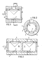
- a rotary slide valve as a 3/3-way valve. It consists of a cylindrical housing 1 with an access opening 2 and two outlet openings 3, 4 as well as a likewise cylindrical actuator 5, rotatably mounted in the housing 1, with two through openings 6, 7, which are assigned to the inlet and outlet openings 2, 3, 4 .
- the actuator 5 is designed as a very thin-walled hollow body which is closed at the end faces. 9 with a drive axis for a rotary drive is designated.
- FIG. 3 shows an embodiment of a rotary slide valve in which a plurality of inlet and outlet lines can be operated synchronously by rotating an actuator 5.
- the actuator divided into several, here two closed chambers 10, 11. Otherwise, this valve is constructed like that of FIGS. 1 and 2.
- valves of FIGS. 1 to 3 are only suitable if there are small pressure differences between the flow channels, since the pressure forces acting radially on the actuator 5 are not balanced. Higher pressure differences would therefore cause relatively high frictional forces between the actuator 5 and the housing 1.
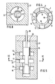
- FIG. 4 an embodiment is provided according to FIG. 4 in which inlet and outlet openings 2, 3, and 4 and 12, 13, 14 are arranged diametrically opposite one another in pairs for similar flows. Accordingly, the actuator 15 has two assigned through openings 6, 16, which connect the access openings 2, 12 each to one or the other pair of outlet openings 3, 13 or 4, 14.
- this embodiment Since no resulting compressive forces act on the actuator 15 in the radial direction in this embodiment, this embodiment is pressure-balanced. It is also suitable for high pressure differences.
- the principle of designing the actuator as a thin-walled hollow body can also be used advantageously with linear slide valves.
- Inlet and outlet openings 22, 23, 24 are provided in a housing 21.
- An actuator 25 is arranged longitudinally in the housing 21. It is shorter than the chamber 28 enclosed by the housing 21 and has two mutually opposite through openings 26, 27. These are designed as slots in the axial direction and extend so far that they enable the optional connection of the inlet and outlet openings 22, 23 and 22, 24.
- the inlet and outlet openings 22, 23 and 24 open into recesses 17, 18, 19 which surround the actuator in a ring and thus relieve pressure.
- the actuator 25 is open at its end faces. At one end it is connected to a drive rod 29 which can be actuated from outside the housing 21.
Abstract
Description
Die Erfindung betrifft ein Mehrwegeventil, insbesondere für druckübertragende Medien, bestehend aus einem Gehäuse mit einer Vielzahl von Zu- und Abgangsöffnungen sowie einem im Gehäuse bewegbaren, als dünnwandiger Hohlkörper ausgebildeten Stellglied mit Einrichtungen zur wahlweisen Verbindung der Zu- und Abgangsöffnungen des Gehäuses.The invention relates to a multi-way valve, in particular for pressure-transmitting media, consisting of a housing with a multiplicity of inlet and outlet openings and an actuator which is movable in the housing and is designed as a thin-walled hollow body with devices for selectively connecting the inlet and outlet openings of the housing.
Stetige Mehrwegeventile, insbesondere Servoventile, dienen in der Fluidtechnik der Einstellung vorbestimmter Volumenströme oder Drücke, z.B. in der Handhabungstechnik, wo neben elektrischen auch hydraulische oder pneumatische freipositionierbare Antriebe eingesetzt werden.Continuous multi-way valves, especially servo valves, are used in fluid technology to set predetermined volume flows or pressures, e.g. in handling technology, where, in addition to electric, hydraulic or pneumatic freely positionable drives are used.
Derartige Antriebe weisen meist einen Linearantrieb (Zylinder) auf, dessen Verdrängerräume über stetige Ventile mit dem Druckmedium versorgt werden. Durch Zufuhr unterschiedlicher Volumenströme lassen sich unterschiedliche Hubgeschwindigkeiten erzielen. Bei federabgestützten Zylindern wird durch Aufbringen eines bestimmten Druckes eine bestimmte Position angefahren. Hierbei sorgen stetige Ventile für die Einhaltung des geforderten Druckes.Such drives usually have a linear drive (cylinder), the displacement spaces of which are supplied with the pressure medium via continuous valves. Different lifting speeds can be achieved by supplying different volume flows. In spring-supported cylinders, a certain position is approached by applying a certain pressure. Constant valves ensure that the required pressure is maintained.
An stetige Ventile werden im allgemeinen hohe Anforderungen hinsichtlich der Verstellgeschwindigkeit gestellt. Vor allem bei der Verwendung gasförmiger Druckmedien kann nur über schnelle Umbelüftungen der Verdrängerräume des Antriebes eine zufriedenstellende Genauigkeit und Laststeifigkeit erzielt werden. Die beweglichen Schieber der bekannten stetigen Ventile sind jedoch relativ schwer, so daß zur schnellen Verstellung hohe Beschleunigungskräfte notwendig sind. Zudem besitzen Linearschieberventile eine relativ große Angriffsfläche für Strömungskräfte, die bei der Drosselung oder Umlenkung von Strömen immer entstehen und das Ventil zu schließen versuchen. Auch diese relativ hohen Kräfte müssen vom elektromechanischen Wandler aufgebracht werden. Es existieren zwar einige Lösungsansätze zur Kompensation der Strömungskräfte an Linearschiebern durch spezielle konstruktive Maßnahmen, jedoch sind diese Maßnahmen alle fertigungstechnisch aufwendig und meistens nicht über den ganzen Arbeitsbereich des Ventils wirksam.Constant valves are generally subject to high demands with regard to the adjustment speed. Especially when using gaseous pressure media, satisfactory accuracy and load rigidity can only be achieved by quickly ventilating the displacement spaces of the drive. However, the movable slide of the known continuous valves are relatively heavy, so that high acceleration forces are necessary for rapid adjustment. In addition, linear slide valves have a relative Large area of attack for flow forces that always arise when throttling or redirecting flows and try to close the valve. These relatively high forces must also be applied by the electromechanical transducer. Although there are some approaches to compensating the flow forces on linear spools by means of special design measures, these measures are all complex in terms of production technology and mostly do not have an effect over the entire working range of the valve.
Um eine ausreichend große Verstellgeschwindigkeit zu erzielen, werden relativ schwere Ventile mit starken und damit entsprechend schweren und großen elektromechanischen Wandlern verwendet.In order to achieve a sufficiently high adjustment speed, relatively heavy valves with strong and thus correspondingly heavy and large electromechanical transducers are used.
Soweit die Aufgabe mit mehrstufigen Ventilen gelöst ist, ergeben sich zusätzliche Probleme hinsichtlich des erhöhten Bauaufwandes und der Empfindlichkeit gegen Verschmutzung.As far as the task is solved with multi-stage valves, there are additional problems with regard to the increased construction costs and the sensitivity to contamination.
Ein Ventil der eingangs genannten Art ist aus der DE-OS 31 49 306 bekannt. Es handelt sich dabei um ein mit einem dünnwandigen Axialschieber als Stellglied ausgestattetes Mehrwegeventil. Das einstückige Stellglied ist in eine Anzahl zylindrischer Abschnitte unterteilt und voll vom zu steuernden Medium umströmt. Dabei wirken starke Strömungskräfte auf die von der Mantelfläche des Stellgliedes gebildeten Ringflächen.A valve of the type mentioned is known from DE-OS 31 49 306. It is a multi-way valve equipped with a thin-walled axial slide valve as an actuator. The one-piece actuator is divided into a number of cylindrical sections and flows completely around the medium to be controlled. Strong flow forces act on the annular surfaces formed by the outer surface of the actuator.
Der Erfindung liegt die Aufgabe zugrunde, ein Mehrwegeventil der eingangs genannten Art so auszubilden, daß es nur geringe Antriebskräfte benötigt, so daß ein vergleichsweise kleiner elektromechanischer Wandler in der Lage ist, relativ große fluidische Leistungen unmittelbar, d.h. ohne Zwischenschaltung eines fluidischen Verstärkers, zu steuern.The invention has for its object to design a multi-way valve of the type mentioned in such a way that it requires only low driving forces, so that a comparatively small electromechanical converter is able to directly, relatively large fluidic powers, i.e. to control without the interposition of a fluidic amplifier.
Dieses Ventil soll fertigungstechnisch einfach ausgebildet und sehr schnell und stetig verstellbar sein. Es soll ferner, bezogen uf seine Durchflußleistung klein bauen, d.h. eine günstige Volumenausnutzung aufweisen.This valve is designed to be simple in terms of production technology and be very quickly and continuously adjustable. It should also be small in relation to its flow rate, ie have a favorable volume utilization.
Die Lösung dieser Aufgabe beteht erfindungsgemäß darin, daß das Stellglied als dünnwandiger Hohlkörper ausgebildet ist.The solution to this problem consists in the fact that the actuator is designed as a thin-walled hollow body.
Infolge der Dünnwandigkeit bietet das Stellglied den Strömungskräften als Angriffsfläche lediglich die kleinen Randflächen der Stellgliedöffnungen, so daß diese Kräfte deutlich geringer sind, als bei bekannten Ventilen. Ferner ergibt die geringe Gesamtmasse des Stellgliedes ein kleines Massenträgheitsmoment.As a result of the thin-walledness, the actuator only offers the flow forces as the contact surface the small edge surfaces of the actuator openings, so that these forces are significantly lower than in known valves. Furthermore, the small total mass of the actuator results in a small moment of inertia.
Beide Eigenschaften bewirken in vorteilhafter Weise, daß nur sehr geringe Antriebskräfte am Stellglied erforderlich sind, so daß es z.B. möglich ist, an der Stellgliedachse unmittelbar einen elektrischen Antrieb anzubringen. Dies gilt sowohl für Drehschieberausbildungen als auch für Linearschieberventile.Both properties have the advantageous effect that only very small driving forces are required on the actuator, so that e.g. it is possible to mount an electric drive directly on the actuator axis. This applies to rotary slide valve designs as well as linear slide valves.
Einzelne Merkmale der Erfindung, z.B. die Durchgangsöffnungen im Stellglied mögen zwar aus anderen Druckschriften, wenngleich in anderem Zusammenhang, bekannt sein, z.B. aus der DE-OS 27 26 503, dem DE-GM 17 50 261 oder der DE-OS 31 26 041, doch sind sie hier bei Axialventilen vorgesehen, die ein dickwandiges, in mehrere Kammern unterteiltes oder zumindest einseitig abgeschlossenes, axial bewegliches, dickwandiges Stellglied aufweisen, das auch nur teilweise durchströmt, im wesentlichen aber umströmt ist und auf das starke Strömungskräfte einwirken.Individual features of the invention, e.g. the through openings in the actuator may be known from other publications, albeit in a different context, e.g. from DE-OS 27 26 503, DE-GM 17 50 261 or DE-OS 31 26 041, but they are provided here for axial valves which have a thick-walled, divided into several chambers or at least one end, axially movable, thick-walled Have actuator which also flows only partially, but is essentially flowed around and act on the strong flow forces.
Eine Kombination dieser bekannten Merkmale mit dem eingangs erwähnten Mehrwegeventil hätte nicht zur Lösung der gestellten Aufgabe geführt.A combination of these known features with the multi-way valve mentioned at the beginning would not have led to the solution of the problem.
In den Unteransprüchen sind vorteilhafte weitere Ausgestaltungen des erfindungsgemäßen Mehrwegeventiles angegeben. Nachstehend ist die Erfindung anhand von in der Zeichnung dargestellten Ausführungsbeispielen näher erläutert. Es zeigen:
- Fig.1 ein Drehschieberventil im Längsschnitt
- Fig.2 einen Querschnitt nach der Linie II-I in Fig.1
- Fig.3 ein Mehrkammer-Drehschieberventil im Längsschnitt
- Fig.4 einen Querschnitt durch ein abgewandeltes, druckentlastetes Drehschieberventil
- Fig.5 einen Längsschnitt durch ein Linearschieberventil und
- Fig.6 einen Querschnitt nach der Linie VI-VI in Fig.5.
- 1 shows a rotary slide valve in longitudinal section
- 2 shows a cross section along the line II-I in Fig.1
- 3 shows a multi-chamber rotary slide valve in longitudinal section
- 4 shows a cross section through a modified, pressure-relieved rotary slide valve
- 5 shows a longitudinal section through a linear slide valve and
- 6 shows a cross section along the line VI-VI in Fig.5.
Die Fig. 1 und 2 zeigen ein Drehschieberventil als 3/3-Wegeventil. Es besteht aus einem zylindrischen Gehäuse 1 mit einer Zugangsöffnung 2 und zwei Abgangsöffnungen 3,4 sowie aus einem ebenfalls zylindrischen, im Gehäuse 1 drehbar gelagerten Stellglied 5 mit zwei Durchgangsöffnungen 6,7, die den Zu- und Abgangsöffnungen 2,3,4 zugeordnet sind.1 and 2 show a rotary slide valve as a 3/3-way valve. It consists of a cylindrical housing 1 with an access opening 2 and two
Das Stellglied 5 ist als sehr dünnwandiger, an den Stirnseiten geschlossener Hohlkörper ausgebildet. Mit 9 ist eine Antriebsachse für einen Drehantrieb bezeichnet.The
Je nach der gegebenen Drehwinkelstellung des Stellgliedes 5 ermöglicht dieses eine Weiterleitung des durch die Zugangsöffnung 2 angebotenen Mediums durch die Abgangsöffnungen 3 oder 4. Infolge der extrem dünnen Wände des Stellgliedes ergeben sich nur vernachlässigbar kleine Strömungskräfte in Umfangsrichtung an den Durchgangsöffnungen 6,7, so daß sich das Stellglied 5 leicht und rasch umschalten läßt.Depending on the given angular position of the
Fig.3 zeigt eine Ausführungsform eines Drehschieberventils, bei dem durch Drehung eines Stellgliedes 5 mehrere Zu- und Abgangsleitungen synchron bedient werden können. Zu diesem Zweck ist das Stellglied in mehrere, hier zwei geschlossene Kammern 10,11 unterteilt. Im übrigen ist dieses Ventil wie dasjenige der Fig.1 und 2 aufgebaut.3 shows an embodiment of a rotary slide valve in which a plurality of inlet and outlet lines can be operated synchronously by rotating an
Die Ventile der Fig.1 bis 3 eignen sich nur dann, wenn zwischen den Strömungskanälen geringe Druckdifferenzen herrschen, da die radial auf das Stellglied 5 wirkenden Druckkräfte nicht ausgeglichen sind. Höhere Druckdifferenzen würden daher relativ hohe Reibungskräfte zwischen dem Stellglied 5 und dem Gehäuse 1 verursachen.The valves of FIGS. 1 to 3 are only suitable if there are small pressure differences between the flow channels, since the pressure forces acting radially on the
Um dies zu vermeiden, ist gemäß Fig.4 eine Ausführungsform vorgesehen, bei der Zu- und Abgangsöffnungen 2, 3, und 4 sowie 12,13,14 für gleichartige Strömungen einander paarweise diametral gegenüberstehend angeordnet sind. Dementsprechend weist das Stellglied 15 zwei zugeordnete Durchgangsöffnungen 6,16 auf, die die Zugangsöffnungen 2,12 jeweils mit dem einen oder anderen Paar Abgangsöffnungen 3,13 bzw 4, 14 verbinden.In order to avoid this, an embodiment is provided according to FIG. 4 in which inlet and
Da bei dieser Ausführungsform keine resultierenden Druckkräfte auf das Stellglied 15 in radialer Richtung wirken, ist diese Ausführungsform druckausgeglichen. Sie ist auch für hohe Druckdifferenzen beeignet.Since no resulting compressive forces act on the
Das Prinzip, das Stellglied als dünnwandigen Hohlkörper auszubilden, ist auch bei Linearschieberventilen mit Vorteil anwendbar.The principle of designing the actuator as a thin-walled hollow body can also be used advantageously with linear slide valves.
Die Fig. 5 und 6 zeigen eine solches Linearschieberventil. In einem Gehäuse 21 sind Zu- und Abgangsöffnungen 22, 23, 24 vorgesehen. Im Gehäuse 21 ist ein Stellglied 25 längsgeführt angeordnet. Es ist kürzer als die vom Gehäuse 21 umschlossene Kammer 28 und weist zwei einander gegenüberliegende Durchgangsöffnungen 26,27 auf. Diese sind in axialer Richtung als Schlitze ausgeführt und reichen soweit, daß sie die wahlweise Verbindung der Zu- und Abgangsöffnungen 22, 23 bzw. 22, 24 ermöglichen.5 and 6 show such a linear slide valve. Inlet and
Die Zu- und Abgangsöffnungen 22, 23 und 24 münden in Ausnehmungen 17, 18, 19, die das Stellglied ringförmig umgeben und damit druckentlasten.The inlet and outlet openings 22, 23 and 24 open into
Das Stellglied 25 ist an seinen Stirnseiten offen. An der einen Stirnseite ist es mit einer Antriebsstange 29 verbunden, die von außerhalb des Gehäuses 21 betätigbar ist.The
Je nach der axialen Stellung des Stellgliedes 25 strömt Medium durch die Zugangsöffnung 22 und die Ausnehmung 17 in das Innere des Stellgliedes 25 und von dort durch die Ausnehmung 18 bzw. 19 zu den Abgangsöffnungen 23 oder 24. Die axiale Verstellung des Stellgliedes erfordert extrem kleine Kräfte. Wegen der völligen Umströmung des Stellgliedes im Bereich der Ausnehmungen 17,18 und 19 ist auch ein völliger Druckausgleich gegeben.Depending on the axial position of the
Claims (5)
dadurch gekennzeichnet,
daß das Stellglied (5,15) ein zylindrischer Hohlkörper ist, dessen Einrichtungen zur Verbindung der Zu- und Abgangsöffnungen (2,3,4; 12,13,14) des Gehäuses (1) aus einer Anzahl diesen zugeordneten Durchgangsöffnungen (6,16,7) bestehen, die eine ausschließliche Durchströmung des Stellgliedes (5,15) gestatten und
daß das Stellglied (5,15) im Gehäuse (1) drehbar gelagert ist und einen Drehantrieb aufweist.1. multi-way valve, in particular for pressure-transmitting media, consisting of a housing with a multiplicity of inlet and outlet openings and an actuator which can be moved in the housing and is designed as a thin-walled hollow body and has devices for selectively connecting the inlet and outlet openings of the housing,
characterized,
that the actuator (5, 15) is a cylindrical hollow body, the devices for connecting the inlet and outlet openings (2, 3, 4; 12, 13, 14) of the housing (1) from a number of these through openings (6, 16 , 7), which allow an exclusive flow through the actuator (5,15) and
that the actuator (5,15) is rotatably mounted in the housing (1) and has a rotary drive.
dadurch gekennzeichnet,
daß das Stellglied (25) ein allgemein rohrförmiger, stirnseitig offener Hohlkörper ist, der kürzer als das Gehäuse (21) und in diesem axial verschiebbar angeordnet ist und einen Axialantrieb (29) aufweist, und
daß seine Einrichtungen zur Verbindung der Zu- und Abgangsöffnungen (22,23,24) des Gehäuses (21) ausschließlich aus einer Anzahl diesen zugeordneten Durchgangsöffnungen (26,27) bestehen, die eine ausschließliche Durchströmung des Stellgliedes (25) gestatten.3. Multi-way valve, in particular for pressure-transmitting media, consisting of a housing with a multiplicity of inlet and outlet openings and an actuator which can be moved in the housing and is designed as a thin-walled hollow body with devices for selectively connecting the inlet and outlet openings of the housing,
characterized,
that the actuator (25) is a generally tubular, open-ended hollow body which is shorter than the housing (21) and axially displaceable in this and has an axial drive (29), and
that its devices for connecting the inlet and outlet openings (22, 23, 24) of the housing (21) consist exclusively of a number of passage openings (26, 27) assigned to them, which permit an exclusive flow through the actuator (25).
Applications Claiming Priority (2)
| Application Number | Priority Date | Filing Date | Title |
|---|---|---|---|
| DE19873714691 DE3714691A1 (en) | 1987-05-02 | 1987-05-02 | MULTI-WAY VALVE |
| DE3714691 | 1987-05-02 |
Publications (3)
| Publication Number | Publication Date |
|---|---|
| EP0289770A2 true EP0289770A2 (en) | 1988-11-09 |
| EP0289770A3 EP0289770A3 (en) | 1989-07-26 |
| EP0289770B1 EP0289770B1 (en) | 1993-07-28 |
Family
ID=6326734
Family Applications (1)
| Application Number | Title | Priority Date | Filing Date |
|---|---|---|---|
| EP19880104710 Expired - Lifetime EP0289770B1 (en) | 1987-05-02 | 1988-03-24 | Directional multiway valve |
Country Status (3)
| Country | Link |
|---|---|
| EP (1) | EP0289770B1 (en) |
| JP (1) | JPS63285303A (en) |
| DE (1) | DE3714691A1 (en) |
Cited By (8)
| Publication number | Priority date | Publication date | Assignee | Title |
|---|---|---|---|---|
| FR2733566A1 (en) * | 1995-04-28 | 1996-10-31 | Vincent Eric | Two three or four way fluid valve |
| WO2008006717A1 (en) * | 2006-07-08 | 2008-01-17 | Schaeffler Kg | Hydraulic control valve |
| WO2011015853A2 (en) | 2009-08-01 | 2011-02-10 | Kohler Mira Limited | Fluid delivery systems |
| WO2014060100A1 (en) * | 2012-10-19 | 2014-04-24 | Daimler Ag | Rotary disk valve for a fuel cell system |
| CN106065961A (en) * | 2016-08-04 | 2016-11-02 | 中国电力工程顾问集团中南电力设计院有限公司 | Independent body rotary valve core pattern Oil Cooler of Steam Turbine clematis stem switching device |
| CN107771241A (en) * | 2015-07-14 | 2018-03-06 | 舍弗勒技术股份两合公司 | Control valve for camshaft adjuster |
| WO2020157612A1 (en) * | 2019-01-28 | 2020-08-06 | Giacomini S.P.A. | Multiway valve with cartridge and fluid mechanics inserts |
| CN112587016A (en) * | 2020-11-19 | 2021-04-02 | 慈溪市万能电子有限公司 | Washing product sterilization and disinfection device |
Families Citing this family (15)
| Publication number | Priority date | Publication date | Assignee | Title |
|---|---|---|---|---|
| SE468188B (en) * | 1991-04-08 | 1992-11-16 | Stiftelsen Inst Foer Mikroelek | METHOD FOR CONNECTING RADIATION IN AN INFRARED DETECTOR, APPLIED DEVICE |
| JPH0643433U (en) * | 1992-11-17 | 1994-06-10 | 象印マホービン株式会社 | Channel switching valve |
| EP0678166B1 (en) * | 1993-11-08 | 1998-08-12 | SIG Schweizerische Industrie-Gesellschaft | Control device for a variable intake volume pump |
| DE19633191C2 (en) * | 1996-08-17 | 1998-07-02 | Daimler Benz Ag | Changeover valve for a pressure medium |
| JP4663844B2 (en) * | 1999-05-13 | 2011-04-06 | 株式会社アマダ | Control valve |
| JP4527410B2 (en) * | 1999-05-13 | 2010-08-18 | 株式会社アマダ | Control valve |
| DE10064671A1 (en) * | 2000-12-21 | 2002-06-27 | Behr Gmbh & Co | Valve for vehicle heating system has sliding element range greater than adjustment range required to regulate one inlet or outlet opening; other openings can be regulated outside this range |
| DE10152186C1 (en) * | 2001-10-23 | 2003-06-12 | Ballard Power Systems | Unit dosing oxygen into gas generator for fuel cell, comprises perforated concentric cylindrical pipes which can be rotated relative to each other |
| DE102007009194B3 (en) * | 2007-02-26 | 2008-09-25 | Kioto Clear Energy Ag | Multi-way valve |
| JP5759105B2 (en) * | 2010-01-21 | 2015-08-05 | 本田技研工業株式会社 | Hydraulic control valve |
| DE102011055902A1 (en) * | 2011-11-30 | 2013-06-06 | Jui-Yuan Cheng | Rotating hydraulic valve i.e. manifold valve, for controlling flow direction of hydraulic oil for operating hydraulic motor, has shaft rotated opposite to body in positions such that openings of body are aligned after openings of shaft |
| DE102013101591B4 (en) * | 2013-02-18 | 2016-12-15 | Schell Gmbh & Co. Kg | angle valve |
| DE102015201366A1 (en) * | 2015-01-27 | 2016-07-28 | Mahle International Gmbh | Valve device, in particular for adjusting a coolant flow in a cooling system for an internal combustion engine of a motor vehicle |
| JP6665799B2 (en) * | 2017-01-23 | 2020-03-13 | トヨタ自動車株式会社 | Fuel tank system |
| DE102018004082B4 (en) | 2017-05-24 | 2023-07-06 | Mann+Hummel Gmbh | Switching valve for adjusting a fluid flow |
Citations (6)
| Publication number | Priority date | Publication date | Assignee | Title |
|---|---|---|---|---|
| US2106572A (en) * | 1934-05-14 | 1938-01-25 | Meagher Andrew Charles | Proportioning valve |
| FR966043A (en) * | 1948-05-05 | 1950-09-28 | Spool valve for automatically controlling the heating and cooling circuits of generators using special liquids as heat vehicles | |
| GB771562A (en) * | 1953-12-22 | 1957-04-03 | British Petroleum Co | Improvements in or relating to valves |
| GB992977A (en) * | 1961-04-08 | 1965-05-26 | Erich Kieback | Four-way valve with rotary slide |
| FR1565901A (en) * | 1967-06-01 | 1969-05-02 | ||
| US3591135A (en) * | 1969-09-05 | 1971-07-06 | Oren E Miller | Form of gate valve |
Family Cites Families (10)
| Publication number | Priority date | Publication date | Assignee | Title |
|---|---|---|---|---|
| GB772719A (en) * | 1953-02-25 | 1957-04-17 | Coal Industry Patents Ltd | Improvements in rotary sleeve valves |
| US2898937A (en) * | 1955-02-23 | 1959-08-11 | Miehle Goss Dexter Inc | Rotary valve structure |
| US3222867A (en) * | 1965-05-10 | 1965-12-14 | Hydraulic Crushers Ltd | Balanced rotary commutating valve |
| DE1750261A1 (en) * | 1968-04-13 | 1971-01-28 | Krupp Gmbh | Start-up shock buffer |
| FR2228999B1 (en) * | 1973-05-11 | 1976-04-23 | Bennes Marrel | |
| DE2726503A1 (en) * | 1977-06-11 | 1978-12-21 | Bosch Gmbh Robert | CONTROL VALVE FOR A HYDRAULIC DIRECTIONAL VALVE |
| US4145958A (en) * | 1977-12-02 | 1979-03-27 | Borg-Warner Corporation | Fluid control system with automatically actuated motor port lock-out valves |
| DE2808447A1 (en) * | 1978-02-28 | 1979-08-30 | Hemscheidt Maschf Hermann | Piston in low viscosity operating liq. compensated valve - has guide surfaces on face sides for control pulses fed from outside |
| DE3126041C2 (en) * | 1981-07-02 | 1985-11-28 | Danfoss A/S, Nordborg | Hydraulic control device with an adjustable throttle |
| DE3149306A1 (en) * | 1981-12-12 | 1983-06-23 | Wabco Steuerungstechnik GmbH & Co, 3000 Hannover | Directional control valve |
-
1987
- 1987-05-02 DE DE19873714691 patent/DE3714691A1/en active Granted
-
1988
- 1988-03-24 EP EP19880104710 patent/EP0289770B1/en not_active Expired - Lifetime
- 1988-04-28 JP JP10436488A patent/JPS63285303A/en active Pending
Patent Citations (6)
| Publication number | Priority date | Publication date | Assignee | Title |
|---|---|---|---|---|
| US2106572A (en) * | 1934-05-14 | 1938-01-25 | Meagher Andrew Charles | Proportioning valve |
| FR966043A (en) * | 1948-05-05 | 1950-09-28 | Spool valve for automatically controlling the heating and cooling circuits of generators using special liquids as heat vehicles | |
| GB771562A (en) * | 1953-12-22 | 1957-04-03 | British Petroleum Co | Improvements in or relating to valves |
| GB992977A (en) * | 1961-04-08 | 1965-05-26 | Erich Kieback | Four-way valve with rotary slide |
| FR1565901A (en) * | 1967-06-01 | 1969-05-02 | ||
| US3591135A (en) * | 1969-09-05 | 1971-07-06 | Oren E Miller | Form of gate valve |
Non-Patent Citations (1)
| Title |
|---|
| THE INSTITUTION OF MECHANICAL ENGINEERS, Band 181, Teil 1, Nr. 4, Seiten 75-88, William Clowes and Sons, Ltd, London and Beccles, GB; M.H. LORENZ et al.: "Oil hydraulic spool valve operating times" * |
Cited By (16)
| Publication number | Priority date | Publication date | Assignee | Title |
|---|---|---|---|---|
| FR2733566A1 (en) * | 1995-04-28 | 1996-10-31 | Vincent Eric | Two three or four way fluid valve |
| WO2008006717A1 (en) * | 2006-07-08 | 2008-01-17 | Schaeffler Kg | Hydraulic control valve |
| CN102667275B (en) * | 2009-08-01 | 2014-06-25 | 柯勒米拉有限公司 | Fluid delivery systems |
| US8939175B2 (en) | 2009-08-01 | 2015-01-27 | Kohler Mira Limited | Fluid delivery systems |
| GB2484882A (en) * | 2009-08-01 | 2012-04-25 | Kohler Mira Ltd | Fluid delivery system |
| CN102667275A (en) * | 2009-08-01 | 2012-09-12 | 柯勒米拉有限公司 | Fluid delivery systems |
| GB2484882B (en) * | 2009-08-01 | 2014-01-01 | Kohler Mira Ltd | Fluid delivery systems |
| WO2011015853A3 (en) * | 2009-08-01 | 2011-04-07 | Kohler Mira Limited | Fluid delivery system |
| WO2011015853A2 (en) | 2009-08-01 | 2011-02-10 | Kohler Mira Limited | Fluid delivery systems |
| WO2014060100A1 (en) * | 2012-10-19 | 2014-04-24 | Daimler Ag | Rotary disk valve for a fuel cell system |
| CN107771241A (en) * | 2015-07-14 | 2018-03-06 | 舍弗勒技术股份两合公司 | Control valve for camshaft adjuster |
| CN107771241B (en) * | 2015-07-14 | 2020-11-03 | 舍弗勒技术股份两合公司 | Control valve for a camshaft adjuster |
| CN106065961A (en) * | 2016-08-04 | 2016-11-02 | 中国电力工程顾问集团中南电力设计院有限公司 | Independent body rotary valve core pattern Oil Cooler of Steam Turbine clematis stem switching device |
| WO2020157612A1 (en) * | 2019-01-28 | 2020-08-06 | Giacomini S.P.A. | Multiway valve with cartridge and fluid mechanics inserts |
| CN112587016A (en) * | 2020-11-19 | 2021-04-02 | 慈溪市万能电子有限公司 | Washing product sterilization and disinfection device |
| CN112587016B (en) * | 2020-11-19 | 2023-04-07 | 慈溪市万能电子有限公司 | Washing product sterilization and disinfection device |
Also Published As
| Publication number | Publication date |
|---|---|
| DE3714691A1 (en) | 1988-12-01 |
| EP0289770A3 (en) | 1989-07-26 |
| EP0289770B1 (en) | 1993-07-28 |
| JPS63285303A (en) | 1988-11-22 |
| DE3714691C2 (en) | 1993-03-11 |
Similar Documents
| Publication | Publication Date | Title |
|---|---|---|
| EP0289770A2 (en) | Directional multiway valve | |
| DE3130056C2 (en) | Control valve arrangement for a pressure medium working cylinder | |
| DE1575576C3 (en) | Control throttle for the supply of hydraulic fluid | |
| DE1285819B (en) | Multiple control valve | |
| DE112007003035T5 (en) | Microvalve device | |
| DE1959764B2 (en) | PRESSURE COMPENSATED CONTROL VALVE FOR HYDRAULIC SYSTEMS | |
| CH637733A5 (en) | HYDRAULIC AFTER CONTROL. | |
| EP0688411A1 (en) | Hydraulic control valve | |
| EP0393345A2 (en) | Hydraulic control device | |
| DE2105225B2 (en) | Flow divider | |
| EP1078167B1 (en) | Microvalve | |
| DE1750745A1 (en) | Rotary valve | |
| DE2153989C2 (en) | Hydrostatic or aerostatic bearing arrangement | |
| EP0238782B1 (en) | 5/3-way valve unit | |
| DE2343662A1 (en) | Hydraulic control device with auxiliary and main control valves - has valve held in neutral position by spring | |
| DE2915096A1 (en) | Pressurised system control valve - has plunger with radial passages connecting unions and ports same planes | |
| EP0121849A2 (en) | Valve arrangement with variable function | |
| DE19633191C2 (en) | Changeover valve for a pressure medium | |
| DE3533037C1 (en) | Regulator which can be inserted into the bearing fluid feedline leading to the bearing pocket of a hydrostatic bearing or guide way | |
| EP0233500B1 (en) | Pressure fluid driven actuator | |
| DE19757157C2 (en) | Hydraulic linear drive | |
| DE3106532C2 (en) | ||
| DE2101493B2 (en) | Electromagnetically operated hydraulic directional valve | |
| DE10164256A1 (en) | Air blowing controller for rotary printing machine, feeds compressed air to ducts selectively depending on valve position such that air flow volume in outlet duct is greater than that of inlet duct | |
| DE2737281B2 (en) | Hydraulic copy processing device |
Legal Events
| Date | Code | Title | Description |
|---|---|---|---|
| PUAI | Public reference made under article 153(3) epc to a published international application that has entered the european phase |
Free format text: ORIGINAL CODE: 0009012 |
|
| AK | Designated contracting states |
Kind code of ref document: A2 Designated state(s): BE CH FR GB IT LI NL SE |
|
| PUAL | Search report despatched |
Free format text: ORIGINAL CODE: 0009013 |
|
| AK | Designated contracting states |
Kind code of ref document: A3 Designated state(s): BE CH FR GB IT LI NL SE |
|
| 17P | Request for examination filed |
Effective date: 19900316 |
|
| 17Q | First examination report despatched |
Effective date: 19910610 |
|
| GRAA | (expected) grant |
Free format text: ORIGINAL CODE: 0009210 |
|
| AK | Designated contracting states |
Kind code of ref document: B1 Designated state(s): BE CH FR GB IT LI NL SE |
|
| PG25 | Lapsed in a contracting state [announced via postgrant information from national office to epo] |
Ref country code: BE Effective date: 19930728 |
|
| ET | Fr: translation filed | ||
| ITF | It: translation for a ep patent filed |
Owner name: MODIANO & ASSOCIATI S.R |
|
| GBT | Gb: translation of ep patent filed (gb section 77(6)(a)/1977) |
Effective date: 19931102 |
|
| PG25 | Lapsed in a contracting state [announced via postgrant information from national office to epo] |
Ref country code: SE Free format text: LAPSE BECAUSE OF NON-PAYMENT OF DUE FEES Effective date: 19940325 |
|
| PLBE | No opposition filed within time limit |
Free format text: ORIGINAL CODE: 0009261 |
|
| STAA | Information on the status of an ep patent application or granted ep patent |
Free format text: STATUS: NO OPPOSITION FILED WITHIN TIME LIMIT |
|
| 26N | No opposition filed | ||
| EUG | Se: european patent has lapsed |
Ref document number: 88104710.4 Effective date: 19941010 |
|
| PGFP | Annual fee paid to national office [announced via postgrant information from national office to epo] |
Ref country code: GB Payment date: 19950313 Year of fee payment: 8 |
|
| PGFP | Annual fee paid to national office [announced via postgrant information from national office to epo] |
Ref country code: CH Payment date: 19950330 Year of fee payment: 8 |
|
| PGFP | Annual fee paid to national office [announced via postgrant information from national office to epo] |
Ref country code: NL Payment date: 19950331 Year of fee payment: 8 |
|
| PG25 | Lapsed in a contracting state [announced via postgrant information from national office to epo] |
Ref country code: GB Effective date: 19960324 |
|
| PG25 | Lapsed in a contracting state [announced via postgrant information from national office to epo] |
Ref country code: LI Effective date: 19960331 Ref country code: CH Effective date: 19960331 |
|
| PG25 | Lapsed in a contracting state [announced via postgrant information from national office to epo] |
Ref country code: NL Effective date: 19961001 |
|
| GBPC | Gb: european patent ceased through non-payment of renewal fee |
Effective date: 19960324 |
|
| REG | Reference to a national code |
Ref country code: CH Ref legal event code: PL |
|
| NLV4 | Nl: lapsed or anulled due to non-payment of the annual fee |
Effective date: 19961001 |
|
| REG | Reference to a national code |
Ref country code: FR Ref legal event code: TP |
|
| PGFP | Annual fee paid to national office [announced via postgrant information from national office to epo] |
Ref country code: FR Payment date: 20000324 Year of fee payment: 13 |
|
| PG25 | Lapsed in a contracting state [announced via postgrant information from national office to epo] |
Ref country code: FR Free format text: LAPSE BECAUSE OF NON-PAYMENT OF DUE FEES Effective date: 20011130 |
|
| REG | Reference to a national code |
Ref country code: FR Ref legal event code: ST |
|
| PG25 | Lapsed in a contracting state [announced via postgrant information from national office to epo] |
Ref country code: IT Free format text: LAPSE BECAUSE OF NON-PAYMENT OF DUE FEES;WARNING: LAPSES OF ITALIAN PATENTS WITH EFFECTIVE DATE BEFORE 2007 MAY HAVE OCCURRED AT ANY TIME BEFORE 2007. THE CORRECT EFFECTIVE DATE MAY BE DIFFERENT FROM THE ONE RECORDED. Effective date: 20050324 |