EP0287932A2 - Dispositif de régulation non linéaire pour moteur à combustion interne - Google Patents
Dispositif de régulation non linéaire pour moteur à combustion interne Download PDFInfo
- Publication number
- EP0287932A2 EP0287932A2 EP88105820A EP88105820A EP0287932A2 EP 0287932 A2 EP0287932 A2 EP 0287932A2 EP 88105820 A EP88105820 A EP 88105820A EP 88105820 A EP88105820 A EP 88105820A EP 0287932 A2 EP0287932 A2 EP 0287932A2
- Authority
- EP
- European Patent Office
- Prior art keywords
- control
- internal combustion
- combustion engine
- intake
- rotational speed
- Prior art date
- Legal status (The legal status is an assumption and is not a legal conclusion. Google has not performed a legal analysis and makes no representation as to the accuracy of the status listed.)
- Granted
Links
- 238000002485 combustion reaction Methods 0.000 title claims abstract description 86
- 238000000034 method Methods 0.000 description 46
- 230000008569 process Effects 0.000 description 20
- 238000004364 calculation method Methods 0.000 description 19
- 230000000694 effects Effects 0.000 description 18
- 101000802640 Homo sapiens Lactosylceramide 4-alpha-galactosyltransferase Proteins 0.000 description 11
- 102100035838 Lactosylceramide 4-alpha-galactosyltransferase Human genes 0.000 description 11
- 238000012545 processing Methods 0.000 description 11
- 230000001186 cumulative effect Effects 0.000 description 10
- 230000008859 change Effects 0.000 description 9
- 230000004044 response Effects 0.000 description 9
- 238000011144 upstream manufacturing Methods 0.000 description 8
- 238000010586 diagram Methods 0.000 description 7
- 238000013461 design Methods 0.000 description 6
- 239000000446 fuel Substances 0.000 description 6
- 239000007789 gas Substances 0.000 description 6
- 239000011159 matrix material Substances 0.000 description 6
- 238000005070 sampling Methods 0.000 description 5
- 230000001133 acceleration Effects 0.000 description 4
- 238000012546 transfer Methods 0.000 description 3
- 230000001052 transient effect Effects 0.000 description 3
- 230000002159 abnormal effect Effects 0.000 description 2
- 230000008901 benefit Effects 0.000 description 2
- 238000004891 communication Methods 0.000 description 2
- 238000001514 detection method Methods 0.000 description 2
- 239000012530 fluid Substances 0.000 description 2
- 238000002347 injection Methods 0.000 description 2
- 239000007924 injection Substances 0.000 description 2
- 238000005259 measurement Methods 0.000 description 2
- 239000000243 solution Substances 0.000 description 2
- 230000003044 adaptive effect Effects 0.000 description 1
- 230000005540 biological transmission Effects 0.000 description 1
- 239000000470 constituent Substances 0.000 description 1
- 238000010276 construction Methods 0.000 description 1
- 239000000498 cooling water Substances 0.000 description 1
- 230000001955 cumulated effect Effects 0.000 description 1
- 230000007423 decrease Effects 0.000 description 1
- 230000000994 depressogenic effect Effects 0.000 description 1
- 230000002542 deteriorative effect Effects 0.000 description 1
- 238000012886 linear function Methods 0.000 description 1
- 239000000203 mixture Substances 0.000 description 1
- 238000012986 modification Methods 0.000 description 1
- 230000004048 modification Effects 0.000 description 1
- 230000002093 peripheral effect Effects 0.000 description 1
- 230000010349 pulsation Effects 0.000 description 1
- 230000003134 recirculating effect Effects 0.000 description 1
- 238000011160 research Methods 0.000 description 1
- 239000004065 semiconductor Substances 0.000 description 1
- 230000003068 static effect Effects 0.000 description 1
Images


Classifications
-
- F—MECHANICAL ENGINEERING; LIGHTING; HEATING; WEAPONS; BLASTING
- F02—COMBUSTION ENGINES; HOT-GAS OR COMBUSTION-PRODUCT ENGINE PLANTS
- F02D—CONTROLLING COMBUSTION ENGINES
- F02D31/00—Use of speed-sensing governors to control combustion engines, not otherwise provided for
- F02D31/001—Electric control of rotation speed
- F02D31/002—Electric control of rotation speed controlling air supply
- F02D31/003—Electric control of rotation speed controlling air supply for idle speed control
- F02D31/005—Electric control of rotation speed controlling air supply for idle speed control by controlling a throttle by-pass
-
- F—MECHANICAL ENGINEERING; LIGHTING; HEATING; WEAPONS; BLASTING
- F02—COMBUSTION ENGINES; HOT-GAS OR COMBUSTION-PRODUCT ENGINE PLANTS
- F02D—CONTROLLING COMBUSTION ENGINES
- F02D41/00—Electrical control of supply of combustible mixture or its constituents
- F02D41/02—Circuit arrangements for generating control signals
- F02D41/14—Introducing closed-loop corrections
- F02D41/1401—Introducing closed-loop corrections characterised by the control or regulation method
-
- F—MECHANICAL ENGINEERING; LIGHTING; HEATING; WEAPONS; BLASTING
- F02—COMBUSTION ENGINES; HOT-GAS OR COMBUSTION-PRODUCT ENGINE PLANTS
- F02D—CONTROLLING COMBUSTION ENGINES
- F02D41/00—Electrical control of supply of combustible mixture or its constituents
- F02D41/02—Circuit arrangements for generating control signals
- F02D41/14—Introducing closed-loop corrections
- F02D41/16—Introducing closed-loop corrections for idling
-
- F—MECHANICAL ENGINEERING; LIGHTING; HEATING; WEAPONS; BLASTING
- F02—COMBUSTION ENGINES; HOT-GAS OR COMBUSTION-PRODUCT ENGINE PLANTS
- F02D—CONTROLLING COMBUSTION ENGINES
- F02D41/00—Electrical control of supply of combustible mixture or its constituents
- F02D41/02—Circuit arrangements for generating control signals
- F02D41/14—Introducing closed-loop corrections
- F02D41/1401—Introducing closed-loop corrections characterised by the control or regulation method
- F02D2041/1413—Controller structures or design
- F02D2041/1415—Controller structures or design using a state feedback or a state space representation
- F02D2041/1416—Observer
-
- F—MECHANICAL ENGINEERING; LIGHTING; HEATING; WEAPONS; BLASTING
- F02—COMBUSTION ENGINES; HOT-GAS OR COMBUSTION-PRODUCT ENGINE PLANTS
- F02D—CONTROLLING COMBUSTION ENGINES
- F02D41/00—Electrical control of supply of combustible mixture or its constituents
- F02D41/02—Circuit arrangements for generating control signals
- F02D41/14—Introducing closed-loop corrections
- F02D41/1401—Introducing closed-loop corrections characterised by the control or regulation method
- F02D2041/1413—Controller structures or design
- F02D2041/143—Controller structures or design the control loop including a non-linear model or compensator
-
- F—MECHANICAL ENGINEERING; LIGHTING; HEATING; WEAPONS; BLASTING
- F02—COMBUSTION ENGINES; HOT-GAS OR COMBUSTION-PRODUCT ENGINE PLANTS
- F02D—CONTROLLING COMBUSTION ENGINES
- F02D41/00—Electrical control of supply of combustible mixture or its constituents
- F02D41/02—Circuit arrangements for generating control signals
- F02D41/14—Introducing closed-loop corrections
- F02D41/1401—Introducing closed-loop corrections characterised by the control or regulation method
- F02D2041/1433—Introducing closed-loop corrections characterised by the control or regulation method using a model or simulation of the system
-
- F—MECHANICAL ENGINEERING; LIGHTING; HEATING; WEAPONS; BLASTING
- F02—COMBUSTION ENGINES; HOT-GAS OR COMBUSTION-PRODUCT ENGINE PLANTS
- F02D—CONTROLLING COMBUSTION ENGINES
- F02D2200/00—Input parameters for engine control
- F02D2200/02—Input parameters for engine control the parameters being related to the engine
- F02D2200/04—Engine intake system parameters
- F02D2200/0402—Engine intake system parameters the parameter being determined by using a model of the engine intake or its components
Definitions
- the present invention relates to a non-linear feedback controller for an internal combustion engine which is effective in stably controlling the rotational speed of the internal combustion engine or in controlling the engine speed so as to converge to a target rotational speed with superior follow-up characteristics by using a parameter which is determined on the basis of a dynamic physical model of the internal combustion engine.
- a technique has heretofore been known by which a dynamic model of an internal combustion engine is constructed on the basis of a control theory that takes into consideration the internal state of the engine, and a variable which is to be input to the internal combustion engine to be controlled is determined by estimating a dynamic behavior of the engine on the basis of state variables which represents the internal state of the engine.
- One example of such technique has been proposed as a "Method of Simultaneously Controlling Idling Speed and Air-Fuel Ratio in Internal Combustion Engine” (Japanese Patent Laid-Open No. 59-7751).
- state variables of appropriate order which represent the dynamic internal state of an internal combustion engine are estimated on the basis of a dynamic model of the engine in which control inputs include the air quantity, the fuel supply quantity and the ignition timing or the exhaust recirculating quantity; control outputs include the idling speed and the air-fuel ratio; and a multi-variable control is effected with the above-described control inputs and outputs.
- control inputs include the air quantity, the fuel supply quantity and the ignition timing or the exhaust recirculating quantity
- control outputs include the idling speed and the air-fuel ratio
- a multi-variable control is effected with the above-described control inputs and outputs.
- the dynamic model and control gain are changed for appropriate other ones, thereby simultaneously effecting optimal control of the rotational speed and air-fuel ratio during idling of the engine in accordance with the dynamics of the engine, and thus realizing even more stable idling.
- the state variables are not required to correspond to various kinds of physical quantities which represent the actual internal state, but these variables generally simulate the engine.
- a parameter e.g., cooling water temperature
- dynamic models are stored in advance in correspondence with various values of the parameter, so that the dynamic models and control gains are changed from one to another in accordance with the value of the parameter.
- the dynamic model thus determined expresses the behavior of the internal combustion engine for perturbations only in the vicinity of a specific operating condition, that is, near the above-described reference set value, and it is a model which does not necessarily have physical meanings. Therefore, in general, the dynamic model does not effectively match the internal combustion engine that is the control object.
- the operating condition of the internal combustion engine changes over a wide range, that is, when the engine is frequently run in transient states at the time, for example, of cold starting, warming-up, idling after the completion of warming-up, heavy-load operation during starting or acceleration, and light-load operation during constant-speed running
- the actual behavior of the internal combustion engine deviates from the predetermined dynamic model to a substantial extent, resulting in a reduced degree of control accuracy. Accordingly, it has heretofore been difficult to effect satisfactory feedback control.
- the above-described prior art is arranged such that a plurality of linear models are determined, corresponding to various operating conditions of an internal combustion engine, and these linear models are changed from one to another to effect accurate control.
- the predetermination of a plurality of linear models complicates the control law, however, and leads to poorer control response and follow-up characteristics.
- control is effected at the boundary region between linear models, it is impossible to predict what kind of phenomenon will occur.
- a control quantity for feedback control is determined on the basis of formula models obtained by making discrete samples of a dynamic physical model of an internal combustion engine by means of sampling effected every predetermined crank angle, the dynamic physical model being constructed using at least a quantity which is equivalent to the pressure of intake air sucked into the engine and a quantity which is equivalent to the rotational speed of the engine.
- the dynamic physical model of the internal combustion engine is based on the assumption that the quantity of air passing through the throttle valve is independent of the intake pressure and proportional only to the opening area of the intake passage.
- the intake pressure exceeds the critical pressure, that is, when the engine is run under a relatively heavy load with a relatively large throttle valve opening, the flow velocity of the intake air passing the vicinity of the throttle valve changes under the effect of the intake pressure, and the above-described assumption is not necessarily valid. Accordingly, in the case where the behavior of the internal combustion engine expressed by the dynamic physical model differs from the actual dynamic behavior of the engine during a heavy-load running at the time, for example, of starting or acceleration, the degree of control accuracy may fall, which means that the above-described improved art is still unsatisfactory.
- the present invention provides a non-linear feedback controller for an internal combustion engine which, as shown in Fig. 1, determines a control quantity which is feedback-input to the internal combustion engine M1 according to a dynamic physical model of the internal combustion engine M1 which is obtained by approximation from an equation of motion of the internal combustion engine M1 and a mathematical formula expressing mass conservation of the quantity of intake air sucked into the internal combustion engine M1, thereby controlling the rotational speed of the internal combustion engine M1, the controller comprising: operating condition detecting means M2 for detecting at least an intake pressure equivalent quantity which is equivalent to an intake pressure of the internal combustion engine M1 and a rotational speed equivalent quantity which is equivalent to a rotational speed of the internal combustion engine M1; opening area controlling means M3 for controlling the opening area of an intake passage of the internal combustion engine M1 in accordance with an external command manipulating quantity; control means M4 for calculating a control quantity concerned with the control of the opening area of the intake passage of the internal combustion engine M1 from at least the intake pressure equivalent quantity and
- the operating condition detecting means M2 detects at least an intake pressure equivalent quantity which is equivalent to an intake pressure in the internal combustion engine M1 and a rotational speed equivalent quantity which is equivalent to a rotational speed of the engine M1.
- the intake pressure equivalent quantity includes various quantities which have a predetermined relationship with the pressure within the intake pipe. It should be noted that the pressure which is to be detected is either a relative pressure or an absolute pressure (a pressure measured relative to a vacuum which is assumed to be 0).
- the rotational speed equivalent quantity includes various quantities in addition to the rotational speed of the engine M1, for example, a rotational speed square value, a rotational angular velocity, or a quantity which is uniquely determined in accordance with the rotational speed of the engine M1.
- the operating condition detecting means M2 may be realized by an intake pressure sensor (vacuum sensor) or the like defined by a semiconductor pressure sensor which is disposed in the intake passage of the internal combustion engine M1 at the downstream side of the throttle valve.
- the operating condition detecting means M2 may comprise, for example, a rotational speed sensor consisting of a pulse gear which is secured to the camshaft of a distributor or a cam position sensor of the internal combustion engine M1 and an electromagnetic pickup which is disposed in close proximity with and in opposing relation to the pulse gear.
- the operating condition detecting means M2 may also be defined by, for example, a rotational speed sensor which detects the rotational speed of the crankshaft of the internal combustion engine M1.
- the operating condition detecting means M2 may comprise, for example, one of the above-described rotational speed sensors, an F/V converter which converts a pulse signal output from the rotational speed sensor into an analog signal, and a multiplier which squares the analog signal. It is also possible to obtain a rotational speed square value by inputting the above-described pulse signal into a logical arithmetic circuit and processing it according to a predetermined procedure.
- the operating condition detecting means M2 may comprise, in addition to the above-described intake pressure sensor and rotational speed sensor, an atmospheric pressure sensor for measuring an atmospheric pressure and an intake air temperature sensor for measuring the temperature of the intake air, the atmospheric pressure sensor and the intake air temperature sensor being disposed in the intake passage of the internal combustion engine M1 at the upstream side of the throttle valve.
- the opening area controlling means M3 controls the opening area of the intake passage of the internal combustion engine M1 in accordance with an external command manipulating quantity.
- the opening area controlling means M3 may be realized using a throttle valve (so-called linkless throttle) which controls the effective opening area of the intake pipe by pivoting in receipt of driving force supplied from an actuator, for example, a DC servomotor which operates in response to a direct current supplied from the outside, or a stepping motor which operates in response to a pulse signal transmitted thereto from the outside.
- the opening area controlling means M3 may also be defined by an idling speed control valve (so-called ISCV) which controls the effective opening area of a bypass which bypasses the throttle valve, the ISCV being activated by means of driving force supplied from an actuator, for example, the above-described stepping motor or a linear solenoid which is driven in response to a duty ratio signal transmitted thereto from the outside. Further, the opening area controlling means M3 may be arranged using, for example, an intake system which has both the above-described linkless throttle and ISCV.
- ISCV idling speed control valve
- the control means M4 calculates a control quantity concerned with the control of the opening area of the intake passage of the internal combustion engine M1 from at least the intake pressure equivalent quantity and rotational speed equivalent quantity detected by the operating condition detecting means M2 by using a parameter set on the basis of the dynamic physical model of the internal combustion engine M1.
- the dynamic physical model of the internal combustion engine may be constructed as follows. First, a first approximate equation is obtained from the equation of motion of the internal combustion engine M1 which is in an operative state, the approximate equation expressing a rotational energy change per predetermined crank angle of the internal combustion engine M1 in the form of a linear combination of at least the intake pressure and load torque. Then, a second approximate equation is obtained from a mathematical formula which expresses mass conservation of the intake air quantity in that cylinder of the internal combustion engine M1 which is in the intake stroke, the second approximate equation expressing an intake pressure change per predetermined crank angle of the engine M1 in the form of a linear combination of at least the intake air quantity and intake pressure per predetermined crank angle.
- the above equations (1) and (2) are expressed in discrete systems, and the suffix k denotes the time of sampling.
- the state variable X(k) is a function of at least the rotational speed square value and intake pressure.
- the input u(k) includes at least the intake air quantity per predetermined crank angle (i.e., a control quantity concerned with the control of the intake air quantity).
- the output Y(k) is a function of at least the rotational speed square value and intake pressure.
- the control means M4 may be realized as follows.
- the control means M4 is arranged either as a regulator which effects so-called state feedback control in which a control quantity ⁇ for example, a quotient obtained from the intake air quantity divided by the rotational speed ⁇ is obtained by multiplying the state variable X(k) ⁇ for example, a function of the intake pipe pressure and rotational speed square value ⁇ by a feedback coefficient matrix, or as a so-called optimal regulator which obtains a control quantity by multiplying the above-described state variable X(k) by an optimal feedback gain, thus calculating an intake air quantity per predetermined crank angle.
- the control means M4 may also be arranged in the form of a so-called servo system wherein, in order to enable the rotational speed square value to follow up a target rotational speed square value in the presence of disturbances, a value which is obtained by multiplying a cumulative deviation (obtained by successively adding deviations of measured rotational speed square values from the target rotational speed square value) by the feedback coefficient matrix, or by that element in the optimal feedback gain which is concerned with the cumulative deviation, is added to the above-described control quantity to thereby calculate a final control quantity.
- the control means M4 may be arranged as a dynamic system which is provided with a so-called observer which estimates an immeasurable state variable from an output of a control object (the internal combustion engine M1 in the case of the present invention) which can be directly measured.
- observer There are known various kinds of observer, for example, a minimal order observer, an identity observer, a dead beat observer, a linear function observer, and an adaptive observer. These observers are described in detail, for example, in David G. Luenberger "introduction to Dynamic Systems--Theory, Models and Applications", John Wiley & Sons, Inc., New York, 1979.
- control means M4 may be provided with, for example, a dynamic compensator which obtains a control law from the output to thereby effect output feedback.
- a dynamic compensator which obtains a control law from the output to thereby effect output feedback.
- the compensating means M5 outputs a manipulating quantity to the opening area controlling means M3 in such a manner that when the intake pressure equivalent quantity detected by the operating condition detecting means M2 is equal to or less than a critical pressure equivalent quantity, a value which is determined on the basis of the control quantity calculated by the control means M4 and a predetermined constant is defined as a manipulating quantity; whereas, when the intake pressure equivalent quantity exceeds the critical pressure equivalent quantity, a value obtained by compensating the control quantity in accordance with the intake pressure equivalent quantity is defined as a manipulating quantity.
- the intake pipe pressure is equal to or less than the critical pressure
- the flow velocity of air sucked into that cylinder of the internal combustion engine M1 which is in the intake stroke is equal to sonic velocity. Therefore, the intake air quantity is proportional to the opening area of the intake passage. Accordingly, it is possible to determine a manipulating quantity on the basis of the control quantity and a predetermined constant.
- the predetermined constant is a value which is calculated on the assumption that, for example, the atmospheric pressure and the intake air temperature are constant.
- the intake pipe pressure exceeds the critical pressure, the flow velocity of air sucked into that cylinder of the internal combustion engine M1 which is in the intake stroke changes in accordance with the size relationship between the intake pipe pressure and the atmospheric pressure. Therefore, it is necessary to subject the control quantity to incremental or decremental compensation in accordance with the level of the intake pipe pressure.
- the compensating means M5 may be arranged such that when a value obtained by dividing the intake pipe pressure by the atmospheric pressure is equal to or less than the critical pressure ratio (about 0.53 in the case of diatomic gases such as air), a manipulating quantity is calculated from the control quantity and the predetermined constant or from a predetermined map; whereas, when the value obtained by dividing the intake pipe pressure by the atmospheric pressure exceeds the critical pressure ratio, the control quantity is compensated in accordance with the level of the intake pipe pressure by the use of a mathematical formula obtained by modifying the energy equation of compressible fluid or a map which is equivalent to said mathematical formula.
- the flow of a compressible fluid inside a duct which is accompanied by a density change due to a pressure difference is described in detail, for example, in A. M. Kuethe and J. D. Schetzer, "Foundations of Aerodynamics", John Wiley & Sons, Inc. (1967) and in Horace Lamb, "Hydrodynamics 6 edition", Cambridge at the University Press (1932).
- control means M4 and compensating means M5 are arranged in the form of a logical arithmetic circuit consisting of, for example, a CPU, ROM and RAM which are well-known, together with other peripheral circuit elements, the circuit realizing the means M4 and M5 according to a predetermined processing procedure.
- the non-linear feedback controller for an internal combustion engine functions as follows.
- the control means M4 calculates a control quantity which is concerned with the control of the opening area of the intake passage of the internal combustion engine M1 from at least the intake pressure equivalent quantity and the rotational speed equivalent quantity which are detected by the operating condition detecting means M2 by the use of a parameter set on the basis of a dynamic physical model of the internal combustion engine M1.
- the compensating means M5 functions so as to output a manipulating quantity to the opening area controlling means M3 in such a manner that when the intake pressure equivalent quantity detected by the operating condition detecting means M2 is equal to or less than a critical pressure equivalent quantity, a value which is determined on the basis of the control quantity calculated by the control means M4 and a predetermined constant is defined as a manipulating quantity; whereas, when the intake pressure equivalent quantity exceeds the critical pressure equivalent quantity, a value obtained by compensating the control quantity in accordance with the intake pressure equivalent quantity is defined as a manipulating quantity.
- a control quantity is calculated using a single control law based on the dynamic physical model of the internal combustion engine M1, and when the intake pressure equivalent quantity is equal to or less than the critical pressure equivalent quantity, a value which is determined on the basis of the calculated control quantity and the predetermined constant is defined as a manipulating quantity; whereas, when the intake pressure equivalent quantity exceeds the critical pressure equivalent quantity, a value obtained by compensating the control quantity in accordance with the intake pressure equivalent quantity is defined as a manipulating quantity, to thereby control the opening area of the intake passage of the internal combustion engine M1.
- the non-linear feedback controller deduces a manipulating quantity by compensating the control quantity calculated on the basis of the control law in accordance with the intake pressure equivalent quantity, thereby matching the control law based on the dynamic physical model with the behavior of the internal combustion engine M1 that is the control object.
- the constituent elements of the present invention function as detailed above to thereby solve the technical problem of the present invention.
- the non-linear feedback controller for an internal combustion engine when the intake pressure equivalent quantity exceeds the critical pressure equivalent quantity, for example, when the internal combustion engine runs under a relatively heavy load or is accelerated, a manipulating quantity is deduced by compensating the control quantity calculated on the basis of a single control law based on the dynamic physical model of the engine in accordance with the intake pressure equivalent quantity, thus controlling the opening area of the intake system of the engine. Therefore, in various kinds of operating conditions, the control law based on the dynamic physical model is effectively matched with the behavior of the internal combustion engine that is the control object. Accordingly, it is advantageously possible to control stably the rotational speed of the internal combustion engine or effect control so that the engine speed converges to a target rotational speed with a considerably high degree of accuracy.
- control is effected using a single control law based on the dynamic physical model of the internal combustion engine, it is unnecessary to change the control law over a wide range of various kinds of operating conditions of the engine. Accordingly, it is possible to simplify the arrangement of the controller and improve the reliability.
- a dynamic physical model is linearilized without deteriorating the dynamic characteristics of an internal combustion engine which has non-linear characteristics, the dynamic physical model is effectively conformable with the behavior of the internal combustion engine that is the control object over a wide range of operating conditions. Therefore, it is possible to effect feedback control of the rotational speed of the internal combustion engine while maintaining a high level of control response and follow-up characteristics at all times.
- FIG. 2 is a system diagram showing the arrangement of one embodiment of the engine controller according to the present invention.
- the engine controller 1 comprises a four-cylinder engine 2 and an electronic control unit (hereinafter referred to as "ECU") 3 which controls the engine 2.
- ECU electronice control unit
- the engine 2 has a first combustion chamber 4 which is defined by a cylinder 4a and a piston 4b, and second to fourth combustion chambers 5, 6 and 7 which have the same arrangement as that of the first combustion chamber 4.
- the combustion chambers 4, 5, 6 and 7 communicate with intake manifolds 12, 13, 14 and 15 through intake valves 8, 9, 10 and 11, respectively.
- a surge tank 16 which absorbs pulsation of intake air is provided at the upstream side of the intake manifolds 12, 13, 14 and 15.
- a throttle valve 18 which controls the amount of intake air is disposed inside an intake pipe 17 which is provided at the upstream side of the surge tank 16.
- the throttle valve 18 is pivoted so as to change the degree of opening thereof by being supplied with driving force from a throttle actuator 19 defined by, for example, a DC motor or a stepping motor, which is activated in response to a control signal delivered from the above-described ECU 3.
- the intake pipe 17 is provided with a throttle bypass 20, and an idling speed control valve (hereinafter referred to as simply "ISCV") 21 is interposed in the bypass 20.
- the opening degree of the ISCV 21 is changed in response to a duty ratio control signal from the ECU 3 and thereby controls the amount of intake air flowing through the bypass 20.
- the engine 2 further has an ignitor 22 equipped with an ignition coil which generates a high voltage required for ignition, and a distributor 24 which distributes the high voltage generated in the ignitor 22 to the respective spark plugs (not shown) of the cylinders in response to the revolution of a crankshaft 23.
- the engine controller 1 has the following sensors for detecting various parameters: an intake pressure sensor 31 which is disposed on the surge tank 16 to detect a level of intake pressure (i.e., pressure within the intake pipe); a rotational speed sensor 32 which outputs a rotational angle signal every 1/24 revolution of the camshaft of the distributor 24, i.e., every time the camshaft rotates an integral multiple of 15° (corresponding to a crank shaft rotation angle of 30°); a throttle position sensor 33 which detects a degree of opening of the throttle valve 18; an atmospheric pressure sensor 34 which is disposed in the intake pipe 17 at the upstream side of the throttle valve 18 to detect a level of atmospheric pressure; an intake-air temperature sensor 35 which is disposed near an air cleaner attached to the intake pipe 17 to measure a temperature of intake air; and an accelerator operated amount sensor 36 which detects an amount by which an accelerator pedal 36a is depressed.
- an intake pressure sensor 31 which is disposed on the surge tank 16 to detect a level of intake pressure (i.e., pressure within the intake pipe);
- the ECU 3 which controls the engine 2 on the basis of these input signals.
- the ECU 3 is arranged in the form of a logical arithmetic circuit which consists mainly of a CPU 3a, a ROM 3b and a RAM 3c, and is connected to an input/output section 3e through a common bus 3d to exchange input/output data with the outside.
- the ECU 3 drives the throttle actuator 19 and the ISCV 21 on the basis of the results of detection which are input thereto from the intake pressure sensor 31, the rotational speed sensor 32, the throttle position sensor 33, the atmospheric pressure sensor 34, the intake-air temperature sensor 35 and the accelerator operated amount sensor 36 and in accordance with programs stored in the ROM 3b in advance, thereby effecting feedback control by which the rotational speed of the engine 2 is made to coincide with a target rotational speed.
- FIG. 3 is a block diagram showing the control system but illustrating no hardware arrangement.
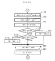
- the control system shown in Fig. 3 consists of discrete systems which are realized in actual practice by execution of a series of programs shown in the flowchart of Fig. 4.
- a first multiplying section P1 calculates a rotational speed square value ⁇ 2 from a rotational speed ⁇ of the engine 2 that is the control object.
- a linear calculation section P2 multiplies both the rotational speed square value ⁇ 2 and an intake pressure P by an element F concerning both the above-described values in an optimal feedback gain F ⁇ (described later) to thereby calculate a first feedback quantity.
- a target rotational speed setting section P3 sets a target rotational speed square value ⁇ r2.
- the target rotational speed ⁇ r is a predetermined rotational speed in an idling state; in a normal running state, it is a command rotational speed given from an automatic transmission controller, or a rotational speed designated by a so-called automatic drive controller, or a result of detection effected by the accelerator operated amount sensor 36.
- the target rotational speed ⁇ r thus determined is squared to set a target rotational speed square value ⁇ r2.
- a successive addition section P4 cumulates deviations e of the rotational speed square value ⁇ 2 from the target rotational speed square value ⁇ r2 to thereby calculate a cumulative deviation ⁇ e.
- a coefficient multiplying section P5 multiplies the cumulative deviation ⁇ e by an element f concerning the cumulative deviation ⁇ e in the optimal feedback gain F ⁇ (described later) to calculate a second feedback quantity.
- a limiter P6 sets upper-limit and lower-limit values for the cumulative deviation ⁇ e. When the cumulative deviation ⁇ e is greater or smaller than the upper-limit or lower-limit value, the limiter P6 limits this cumulative value to the upper-limit or lower-limit value.
- the limiter P6 functions as follows. In the case where it is impossible to make the rotational speed square value ⁇ 2 coincident with the target rotational speed square value ⁇ r2 due to a certain cause, the absolute value of the cumulative deviation ⁇ e may become large without any restriction. In such a case, if no limiter is provided, abnormal control may be conducted when the disturbance causing the deviation disappears. Thus, the limiter P6 serves to prevent such abnormal control.
- the limiter P6 also functions to minimize overshoot and undershoot which are attributable to the cumulative deviation ⁇ e.
- a second multiplying section P7 multiplies the control quantity m/ ⁇ by a rotational speed ⁇ to thereby calculate an intake air quantity m for the engine 2.
- a non-linear calculation section P8 calculates a manipulating quantity S by which the area of opening of the intake passage of the engine 2 is controlled in such a manner that, when the intake pressure P of the engine 2 is not higher than a critical pressure Pc, the non-linear calculation section P8 multiplies the intake air quantity m by a predetermined constant, whereas, when the intake pressure P exceeds the critical pressure Pc, the calculation section P8 multiplies the intake air quantity m by a value which is determined in accordance with the level of the intake pressure P. It should be noted that the effect of changes in the intake pressure P on the intake air quantity m will be described hereinafter.
- the above-described manipulating quantity S is equivalent to an effective cross-sectional area of the intake passage of the engine 2. In other words, the manipulating quantity S is equivalent to the sum of the degrees of opening of the throttle valve 18 and the ISCV 21.
- the effect of the intake pressure P of the engine 2 on the intake air quantity m will be explained. Since the flow of intake air which passes through a throttle portion defined between the inner surface of the intake pipe 17 of the engine 2 and the throttle valve 18 is only slightly affected by viscosity, it is possible to regard changes in the intake air quantity as approximately homoentropic changes. Accordingly, the quantity of intake air passing through the throttle valve may be expressed by the following version of the St.
- m S ⁇ [ ⁇ (2 ⁇ K)/(K-1) ⁇ PO ⁇ 0 ⁇ (P/PO) 2/K - (P/PO) K+1/K ⁇ ] 1/2 ...(3)
- m is the quantity of intake air passing through the throttle valve
- S is the effective throttle valve opening area
- K is the ratio of specific heats of intake air
- PO is pressure at the upstream side of the throttle valve (e.g., atmospheric pressure)
- ⁇ 0 is the density of intake air
- P intake pressure.
- the quantity m of intake air passing through the throttle valve is a function of the effective throttle valve opening area S, intake pressure P, throttle valve upstream-side pressure PO, and throttle valve upstream-side temperature TO.
- the intake air quantity m reaches its maximum when the following equation (7) holds with respect to the pressure ratio P/PO.
- a pressure P which satisfies the conditions of the above-described equation (7) is referred to as the critical pressure, and the flow velocity of intake air which passes through the throttle valve when the internal pressure P is not higher than the critical pressure equals sonic velocity.
- the intake air quantity m is held at the maximum value m max expressed by the above-described equation (9): P/PO ⁇ ⁇ 2/(K+1) ⁇ K/(K-1) ...(10)
- the intake pressure P when the intake pressure P is not higher than the critical pressure, that is, when the engine is running under a relatively light load, the quantity m of intake air passing through the throttle valveis proportional to the effective throttle valve opening area S.
- the intake pressure P exceeds the critical pressure, that is, when the engine is running under a relatively heavy load, the intake air quantity m is affected to a substantial extent by changes in the intake pressure P in addition to the effective throttle valve opening area S and is also somewhat affected by changes in the throttle valve upstream-side pressure PO and the throttle valve upstream-side temperature TO.
- the intake air quantity m is calculated on the basis of the above-described equation (9); whereas, when the intake pressure P exceeds the critical pressure, the intake air quantity m is calculated on the basis of the equations (5) and (6), with the intake pressure P used as a parameter, and an effective throttle valve opening area S is obtained from the intake air quantity m thus calculated.
- the effective throttle valve opening area S may be obtained from the intake air quantity m and the intake pressure P by direct calculation using the equation (9) or the equations (5) and (6). It is also possible to obtain the effective throttle valve opening area S by calculating a corresponding value by means of interpolation using an approximate expression of each of the above-described equations, or a table or map prepared by calculating values of the equations in advance.
- a dynamic physical model of the engine 2 is constructed as follows.
- the equation of motion of the engine 2 which is in an operative state may be expressed as follows: where ⁇ is the rotational speed, t is time, I is the inertia moment of the rotational portion of the engine, n is the number of cylinders, Pci is the pressure within the i-th cylinder, Pa is the atmospheric pressure, ⁇ is the crank angle, Vci is the volume of i-th cylinder, Tf is the mechanical loss of torque, and Tl is the actual load torque.
- P is the intake pressure (pressure in the intake pipe)
- C is the velocity of sound
- m is the quantity of intake air sucked into the combustion chamber through the throttle valve
- Kc is the ratio of specific heats of fuel-air mixture
- qm is the heat transfer quantity of the wall surface of the cylinder
- Ki is the ratio of specific heats of intake air
- Ri is the gas constant of intake air
- Ti is the temperature of intake air
- V is the volume of intake air.
- Tf ⁇ 2 + ⁇ ...(25)
- T ⁇ Tl + ⁇ / ⁇ 3 ...(26)
- ⁇ 2(k+1) ⁇ 1 ⁇ 2(k) + ⁇ 2 ⁇ P(k) + ⁇ 3 ⁇ T ⁇ (k) ...(27)
- P(k) ⁇ 4 ⁇ P(k) + ⁇ 5 ⁇ m(k)/ ⁇ (k) ⁇ ...(28)
- e(k) ⁇ (k)2 - ⁇ r2 ...(31)
- e(k) e(k-1) + ⁇ (k)2 ...(33)
- ⁇ X(k+1) Pa ⁇ X(k) + Ga ⁇ u(k) ...(35)
- the discrete quadratic criterion function may be expressed as follows:
- control quantity m(k)/ ⁇ (k) is determined as follows:
- Step 100 are executed initialization processings such as clearing of registers inside the CPU 3a, setting of an initial value for the second feedback quantity ie, and setting of an upper-limit value iemax and a lower-limit value iemin for the second feedback quantity ie.
- a target rotational speed ⁇ r is read.
- Step 120 a target rotational speed square value ⁇ r2 is calculated.
- the processings carried out in Steps 110 and 120 function in combination as the target rotational speed setting section P3 shown in Fig. 3.
- Step 130 are read a rotational speed ⁇ (k), an intake pressure P(k), a throttle valve upstream-side pressure ⁇ atmospheric pressure ⁇ PO(k) and an intake air temperature (throttle valve upstream-side temperature) TO(k). Then, the process proceeds to Step 140, where a rotational speed square value ⁇ (k)2 is calculated from the rotational speed ⁇ (k) read in Step 130.
- the procedure carried out in Step 140 functions as the first multiplying section P1 shown in Fig. 3.
- Step 160 functions as the second multiplying section P7 shown in Fig. 3.
- Step 180 it is judged whether or not the pressure ratio C calculated in accordance with the equation (44) is equal to or less than a critical pressure ratio, i.e., 0.53. If YES, the process proceeds to Steps 190; whereas, if NO is the answer, the process proceeds to Step 200.
- a critical pressure ratio i.e. 0.53.
- Step 190 which is executed when the pressure ratio C is equal to or less than the critical pressure ratio 0.53, that is, when the flow velocity of intake air passing through the throttle valve is equal to the sound velocity, the value of the function ⁇ is set at 0.484 which is determined on the basis of the aforementioned equation (8), and thereafter the process proceeds to Step 210.
- the specific heat ratio K was calculated as being 1.4.
- Step 200 which is executed when the pressure ratio C exceeds the critical pressure ratio 0.53, that is, when the flow velocity of intake air passing through the throttle valve is lowered by the effect of the intake pressure P, the value of the function ⁇ is calculated on the basis of the aforementioned equation (6) in a manner shown in the following equation (45), and thereafter the process proceeds to Step 210.
- ⁇ ⁇ 3.5 ⁇ (C 1.4 - C 1.7 ) ⁇ 1/2 ...(45)
- an effective throttle valve opening area S which is manipulating quantity is calculated as shown in the following equation (46) on the basis of the aforementioned equation (5) using the function ⁇ obtained in either Step 190 or 200.
- S(k) 0.21 ⁇ 10 ⁇ 2 ⁇ m(k)/ ⁇ ...(46)
- the gas constant R is set at 287.1 [J/Kg. o K], and a value obtained by actual measurement may be employed as the intake air temperature (throttle valve upstream-side temperature) TO(k). Since the intake air temperature TO(k) changes only relatively gently, it may also be calculated, for example, as being a constant having a value of 303 [ o K].
- Steps 180 to 210 function in combination as the non-linear calculation section P8 shown in Fig. 3.
- Step 230 functions as both the successive addition section P4 and coefficient multiplying section P5 which are shown in Fig. 3.
- Step 240 it is judged whether or not the second feedback quantity ie calculated in Step 230 is equal to or less than the upper-limit value iemax. If YES, the process proceeds to Step 250; whereas, if NO is the answer, the process proceeds to Step 260.
- Step 260 which is executed when the second feedback quantity ie is judged to be in excess of the upper-limit value iemax, the second feedback quantity ie is set to the upper-limit value iemax, and the process proceeds to Step 280.
- Step 250 which is executed when it is judged in Step 240 that the second feedback quantity ie is equal to or less than the upper-limit value iemax, a judgment is made as to whether or not the second feedback quantity ie is equal to or more than the lower-limit value iemin. If YES, the process proceeds to Step 280; whereas, if NO is the answer, the process proceeds to Step 270.
- Step 270 which is executed when the second feedback quantity ie is judged to be less than the lower-limit value iemin, the second feedback quantity ie is set to the lower-limit value iemin, and the process proceeds to Step 280.
- Steps 240 to 270 function in combination as the limiter P6 shown in Fig. 3.
- Step 280 a driving signal which is equivalent to the effective throttle valve opening area S(k) calculated in Step 210 as a manipulating quantity is output to either the throttle actuator 19 or the ISCV 21 through the input/output section 3e.
- Step 290 a value 1 is added to the suffix K which denotes the number of cycles of sampling, calculation and control that have been done, thereby renewing the suffix K, and the process then returns to the Step 110. Thereafter, the above-described Steps 110 to 290 are executed repeatedly.
- the intake air quantity m which is deduced from the control quantity m/ ⁇ calculated using the optimal feedback gain F ⁇ obtained on the basis of the dynamic physical model using the rotational speed square value ⁇ 2 and intake pressure P of the engine 2 as state variables is compensated in accordance with the level of the intake pressure P to thereby determine an effective throttle valve opening area S which is a manipulating quantity. Therefore, it is possible to considerably improve response and follow-up characteristics in the rotational speed control of the engine 2 and thus increase the degree of accuracy in the control by a large margin.
- this embodiment is arranged such that the intake air quantity m is first deduced from a control quantity m/ ⁇ which is calculated on the basis of a single control law according to one and only dynamic physical model of the engine 2 and the effective throttle valve opening area S is then calculated from both the intake air quantity m and the intake pressure P, it is possible with a single control law to cope with the operating conditions of the engine 2 over a wide range. This avoids the prior complicated and troublesome control procedures in which control laws are changed from one to another in accordance with the operating conditions. Thus, it is possible to simplify the arrangement of the controller and improve the reliability.
- the idling speed is maintained at a target idling speed by optimal opening control effected by the ISCV 21, so that the stability in the idling speed control is enhanced.
- the throttle valve opening is controlled so as to be optimal by the operation of the throttle actuator 19.
- the function ⁇ is obtained in Step 200 of the engine control processing by subjecting the pressure ratio C to exponential calculation
- the arrangement may be such that the function ⁇ is obtained by performing approximate calculation with respect to the exponential calculation or it is obtained by, for example, interpolation using a map or the like containing results of exponential calculation of a predetermined number of pressure ratios C obtained in advance, whereby the calculation speed can be increased.
- a dynamic physical model which uses the rotational speed square value ⁇ 2 and intake pressure P of the engine 2 as state variables is constructed and a first feedback quantity is obtained in the linear calculation section P2 by performing linear calculation using the state variables and the optimal feedback gain F ⁇ .
- the arrangement may be such that an estimated load torque value T ⁇ for the engine 2 is calculated by using an observer, a dynamic physical model which uses the estimated load torque value T ⁇ , rotational speed square value ⁇ 2 and intake pressure P as state variables is constructed, and a first feedback quantity is obtained by linear calculation using these state variables and an optimal feedback gain Fa ⁇ obtained by enlarging the dynamic physical model into a servo system. More specifically, as shown in Fig. 5, an observer P10 is employed which calculates the estimated load torque value T ⁇ from the control quantity m/ ⁇ , rotational speed square value ⁇ 2 and intake pressure P.
- control system shown in Fig. 5 is a servo system obtained by enlarging the dynamic physical model, it will be explained hereinafter as a control system which is directly concerned with the design of the observer 10, that is, as a control system which is in the form of a mere regulator before the enlargement into a servo system.
- the dynamic physical model in this case may be expressed by the following state equation (49) and output equation (50):
- the observer may be designed according to a known method such as the Gopinath design method (cf. B. Gopinath, "On the Control of Linear Multiple Input-Output Systems", The Bell Technical Journal (1971)). Although various observer designing methods are known and detailed, for example, in Katsuhisa Furuta et al. "Basic System Theory” (1978), Coronasha, Ltd., the observer is designed herein as a minimal order observer according to the Gopinath design method.
- the control system that uses the observer P10 as described above can be realized, for example, by executing Steps 310 to 350 shown in Fig. 6 in place of Step 150 in the engine control processing shown in Fig. 4 in accordance with the already-described embodiment. More specifically, as shown in Fig. 6, an estimated load torque value T ⁇ (k) is calculated in Steps 310 and 320.
- Steps 310 and 320 function in combination as the observer P10 shown in Fig. 5.
- Step 340 functions as the linear calculation section P12 shown in Fig. 5.
- Step 350 a signal which is equivalent to the estimated actual load torque T ⁇ l(k) calculated in Step 330 is output to the outside through the input/output section 3e.
- a control system which has a dynamic compensator P20 and which is realized by dynamic feedback using feedback elements which have dynamic characteristics as shown in Fig. 7.
Applications Claiming Priority (2)
| Application Number | Priority Date | Filing Date | Title |
|---|---|---|---|
| JP98344/87 | 1987-04-21 | ||
| JP62098344A JPH081146B2 (ja) | 1987-04-21 | 1987-04-21 | 内燃機関の非線形フイ−ドバツク制御装置 |
Publications (3)
| Publication Number | Publication Date |
|---|---|
| EP0287932A2 true EP0287932A2 (fr) | 1988-10-26 |
| EP0287932A3 EP0287932A3 (en) | 1989-08-02 |
| EP0287932B1 EP0287932B1 (fr) | 1991-10-16 |
Family
ID=14217286
Family Applications (1)
| Application Number | Title | Priority Date | Filing Date |
|---|---|---|---|
| EP88105820A Expired EP0287932B1 (fr) | 1987-04-21 | 1988-04-12 | Dispositif de régulation non linéaire pour moteur à combustion interne |
Country Status (4)
| Country | Link |
|---|---|
| US (1) | US4860707A (fr) |
| EP (1) | EP0287932B1 (fr) |
| JP (1) | JPH081146B2 (fr) |
| DE (1) | DE3865501D1 (fr) |
Cited By (4)
| Publication number | Priority date | Publication date | Assignee | Title |
|---|---|---|---|---|
| EP0337366A2 (fr) * | 1988-04-12 | 1989-10-18 | Toyota Jidosha Kabushiki Kaisha | Méthode non-linéaire de régulation pour moteur à combustion interne et dispositif à cet effet |
| EP0393642A2 (fr) * | 1989-04-20 | 1990-10-24 | Kabushiki Kaisha Toyota Chuo Kenkyusho | Appareil de commande de régime pour moteur à combustion interne |
| EP0456616A1 (fr) * | 1990-05-07 | 1991-11-13 | FIAT AUTO S.p.A. | Méthode et équipement de commande du régime au ralenti d'un moteur à combustion interne |
| EP2055918A1 (fr) * | 2007-10-31 | 2009-05-06 | Fiat Group Automobiles S.p.A. | Procédé et dispositif d'estimation du débit d'air d'entrée dans un moteur à combustion interne |
Families Citing this family (19)
| Publication number | Priority date | Publication date | Assignee | Title |
|---|---|---|---|---|
| US4974563A (en) * | 1988-05-23 | 1990-12-04 | Toyota Jidosha Kabushiki Kaisha | Apparatus for estimating intake air amount |
| DE3911706C2 (de) * | 1989-04-10 | 1999-09-30 | Linde Ag | Verfahren zum Betreiben einer Antriebseinheit |
| EP0474871B1 (fr) * | 1989-12-25 | 1995-10-25 | Nippondenso Co., Ltd. | Unite de commande numerique |
| JP3289277B2 (ja) * | 1990-01-12 | 2002-06-04 | 株式会社デンソー | エンジン用補助空気量制御装置 |
| DE4006273A1 (de) * | 1990-02-28 | 1991-09-26 | Forsch Kraftfahrwesen Und Fahr | Verfahren und vorrichtung zur ermittlung des verlaufs des innendrucks eines zylinders einer kolbenmaschine |
| JP2696431B2 (ja) * | 1990-12-17 | 1998-01-14 | 株式会社ユニシアジェックス | 内燃機関のアイドル回転数制御装置 |
| EP0633395B1 (fr) * | 1991-06-10 | 1998-08-19 | Denso Corporation | Appareil pour régler la vitesse d'un moteur à combustion interne |
| JPH0650195A (ja) * | 1992-07-30 | 1994-02-22 | Nippondenso Co Ltd | 内燃機関の回転数制御装置 |
| US6039028A (en) * | 1999-01-14 | 2000-03-21 | Ford Global Technologies, Inc. | Active engine speed pulsation damping |
| JP4017336B2 (ja) * | 2000-10-25 | 2007-12-05 | トヨタ自動車株式会社 | 流量算出装置 |
| JP2004197614A (ja) * | 2002-12-17 | 2004-07-15 | Toyota Motor Corp | 内燃機関の圧力・温度算出装置 |
| JP4045957B2 (ja) * | 2003-01-16 | 2008-02-13 | いすゞ自動車株式会社 | 燃料噴射量制御装置 |
| JP4362826B2 (ja) * | 2004-11-18 | 2009-11-11 | トヨタ自動車株式会社 | 内燃機関の制御装置および空燃比算出方法 |
| US7890311B2 (en) * | 2005-07-07 | 2011-02-15 | United States Of America As Represented By The Administrator Of The National Aeronautics And Space Adminstration | Method of simulating flow-through area of a pressure regulator |
| DE102007012340B3 (de) * | 2007-03-14 | 2008-05-15 | Siemens Ag | Verfahren zum Ermitteln und Einregeln des Luftmassenstroms im Saugrohr eines Verbrennungsmotors sowie zugehöriges Steuergerät |
| JP5169854B2 (ja) * | 2009-01-15 | 2013-03-27 | トヨタ自動車株式会社 | 内燃機関の吸入空気量推定装置 |
| JP5362595B2 (ja) * | 2010-01-06 | 2013-12-11 | 本田技研工業株式会社 | 内燃機関の吸入空気量パラメータ算出装置および制御装置 |
| JP6060812B2 (ja) * | 2013-05-17 | 2017-01-18 | 株式会社デンソー | エンジン制御装置 |
| JP6396483B2 (ja) * | 2013-10-30 | 2018-09-26 | エーエスエムエル ネザーランズ ビー.ブイ. | リソグラフィにおける対象物の位置決め |
Citations (5)
| Publication number | Priority date | Publication date | Assignee | Title |
|---|---|---|---|---|
| GB2161626A (en) * | 1984-07-13 | 1986-01-15 | Motorola Inc | Engine control system including idle speed control |
| US4572127A (en) * | 1985-04-01 | 1986-02-25 | Ford Motor Company | Interactive spark and throttle idle speed control |
| EP0176323A2 (fr) * | 1984-09-19 | 1986-04-02 | Nippondenso Co., Ltd. | Commande d'injection de carburant pour moteurs Diesel à minimisation de durée |
| EP0206271A1 (fr) * | 1985-06-24 | 1986-12-30 | Honda Giken Kogyo Kabushiki Kaisha | Appareil de commande du nombre de rotations à vide pour moteurs à combustion interne |
| EP0206272A2 (fr) * | 1985-06-28 | 1986-12-30 | Honda Giken Kogyo Kabushiki Kaisha | Appareil de commande de la vitesse de ralenti d'un moteur à combustion interne |
Family Cites Families (7)
| Publication number | Priority date | Publication date | Assignee | Title |
|---|---|---|---|---|
| US4305360A (en) * | 1979-12-31 | 1981-12-15 | Acf Industries, Inc. | Engine automatic idle speed control apparatus |
| DE3222363A1 (de) * | 1982-06-15 | 1983-12-15 | Robert Bosch Gmbh, 7000 Stuttgart | Anordnung zur drehzahlregelung einer brennkraftmaschine |
| JPS597751A (ja) * | 1982-07-07 | 1984-01-14 | Nissan Motor Co Ltd | 内燃機関におけるアイドル回転速度と空燃比の同時制御方法 |
| JPS5951150A (ja) * | 1982-09-16 | 1984-03-24 | Nissan Motor Co Ltd | 内燃機関のアイドル回転速度制御方法 |
| JPH0697003B2 (ja) * | 1984-12-19 | 1994-11-30 | 日本電装株式会社 | 内燃機関の運転状態制御装置 |
| JP2542568B2 (ja) * | 1985-04-02 | 1996-10-09 | 三菱電機株式会社 | 内燃機関の回転数制御装置 |
| IT1185801B (it) * | 1985-06-11 | 1987-11-18 | Weber Spa | Sistema di controllo automatico del regime di rotazione minimo di un motore endotermico |
-
1987
- 1987-04-21 JP JP62098344A patent/JPH081146B2/ja not_active Expired - Fee Related
-
1988
- 1988-03-29 US US07/174,962 patent/US4860707A/en not_active Expired - Lifetime
- 1988-04-12 EP EP88105820A patent/EP0287932B1/fr not_active Expired
- 1988-04-12 DE DE8888105820T patent/DE3865501D1/de not_active Expired - Lifetime
Patent Citations (6)
| Publication number | Priority date | Publication date | Assignee | Title |
|---|---|---|---|---|
| GB2161626A (en) * | 1984-07-13 | 1986-01-15 | Motorola Inc | Engine control system including idle speed control |
| GB2189058A (en) * | 1984-07-13 | 1987-10-14 | Motorola Inc | Engine idle speed control |
| EP0176323A2 (fr) * | 1984-09-19 | 1986-04-02 | Nippondenso Co., Ltd. | Commande d'injection de carburant pour moteurs Diesel à minimisation de durée |
| US4572127A (en) * | 1985-04-01 | 1986-02-25 | Ford Motor Company | Interactive spark and throttle idle speed control |
| EP0206271A1 (fr) * | 1985-06-24 | 1986-12-30 | Honda Giken Kogyo Kabushiki Kaisha | Appareil de commande du nombre de rotations à vide pour moteurs à combustion interne |
| EP0206272A2 (fr) * | 1985-06-28 | 1986-12-30 | Honda Giken Kogyo Kabushiki Kaisha | Appareil de commande de la vitesse de ralenti d'un moteur à combustion interne |
Cited By (9)
| Publication number | Priority date | Publication date | Assignee | Title |
|---|---|---|---|---|
| EP0337366A2 (fr) * | 1988-04-12 | 1989-10-18 | Toyota Jidosha Kabushiki Kaisha | Méthode non-linéaire de régulation pour moteur à combustion interne et dispositif à cet effet |
| EP0337366A3 (fr) * | 1988-04-12 | 1990-03-07 | Toyota Jidosha Kabushiki Kaisha | Méthode non-linéaire de régulation pour moteur à combustion interne et dispositif à cet effet |
| US5010866A (en) * | 1988-04-12 | 1991-04-30 | Toyota Jidosha Kabushiki Kaisha | Nonlinear feedback control method and apparatus for an internal combustion engine |
| EP0393642A2 (fr) * | 1989-04-20 | 1990-10-24 | Kabushiki Kaisha Toyota Chuo Kenkyusho | Appareil de commande de régime pour moteur à combustion interne |
| EP0393642A3 (fr) * | 1989-04-20 | 1991-07-10 | Kabushiki Kaisha Toyota Chuo Kenkyusho | Appareil de commande de régime pour moteur à combustion interne |
| EP0456616A1 (fr) * | 1990-05-07 | 1991-11-13 | FIAT AUTO S.p.A. | Méthode et équipement de commande du régime au ralenti d'un moteur à combustion interne |
| EP2055918A1 (fr) * | 2007-10-31 | 2009-05-06 | Fiat Group Automobiles S.p.A. | Procédé et dispositif d'estimation du débit d'air d'entrée dans un moteur à combustion interne |
| US8224592B2 (en) | 2007-10-31 | 2012-07-17 | Fiat Group Automobiles S.P.A. | Method and device for estimating the intake air flow rate in an internal combustion engine |
| RU2488011C2 (ru) * | 2007-10-31 | 2013-07-20 | ФИАТ ГРУП АУТОМОБИЛЕС С.п.А. | Способ определения расхода воздуха на входе в двигатель внутреннего сгорания и двигатель внутреннего сгорания |
Also Published As
| Publication number | Publication date |
|---|---|
| DE3865501D1 (de) | 1991-11-21 |
| US4860707A (en) | 1989-08-29 |
| JPS63263238A (ja) | 1988-10-31 |
| JPH081146B2 (ja) | 1996-01-10 |
| EP0287932A3 (en) | 1989-08-02 |
| EP0287932B1 (fr) | 1991-10-16 |
Similar Documents
| Publication | Publication Date | Title |
|---|---|---|
| EP0287932B1 (fr) | Dispositif de régulation non linéaire pour moteur à combustion interne | |
| US5282449A (en) | Method and system for engine control | |
| US6065449A (en) | Fuel injection control device for an internal combustion engine | |
| US4987888A (en) | Method of controlling fuel supply to engine by prediction calculation | |
| EP0312835B1 (fr) | Appareil de commande | |
| EP0185552B1 (fr) | Dispositif pour la commande du fonctionnement d'un moteur à combustion interne | |
| EP0337366A2 (fr) | Méthode non-linéaire de régulation pour moteur à combustion interne et dispositif à cet effet | |
| KR930002080B1 (ko) | 내연기관의 아이들회전수 제어장치 | |
| US7457701B2 (en) | Air quantity estimation apparatus for internal combustion engine | |
| EP1817488B1 (fr) | Appareil de commande du rapport air-carburant d'un moteur a combustion interne | |
| JP2512787B2 (ja) | 内燃機関のスロットル開度制御装置 | |
| US4789939A (en) | Adaptive air fuel control using hydrocarbon variability feedback | |
| US5349932A (en) | Method and device for control of the richness of the air/fuel feed mixture of an internal combustion engine | |
| JP2000097086A (ja) | エンジンの吸入空気流量制御方法、制御装置および出力制御方法 | |
| EP0518289B1 (fr) | Appareil pour régler la vitesse d'un moteur à combustion interne | |
| US5277164A (en) | Method and apparatus for control of engine fuel injection | |
| US5706782A (en) | Engine control system | |
| JP2564806B2 (ja) | 内燃機関のフイ−ドバツク制御方法 | |
| WO2020235689A1 (fr) | Procédé de commande de moteur, système de commande de moteur et navire | |
| US8538660B2 (en) | Vehicle control apparatus and control method | |
| EP1416141B1 (fr) | Procédé et dispositif pour l'estimation et la contrôle de la quantité d'air aspiré d'un cylindre d'un moteur à combustion interne | |
| US20050021215A1 (en) | Method for determining an estimated value of a mass flow in the intake channel of an internal combustion engine | |
| US4901699A (en) | System for controlling a fuel injection quantity and method therefor | |
| US20020179055A1 (en) | Method of operating an internal combustion engine | |
| JP2564808B2 (ja) | 内燃機関の非線形フイ−ドバツク制御方法 |
Legal Events
| Date | Code | Title | Description |
|---|---|---|---|
| PUAI | Public reference made under article 153(3) epc to a published international application that has entered the european phase |
Free format text: ORIGINAL CODE: 0009012 |
|
| AK | Designated contracting states |
Kind code of ref document: A2 Designated state(s): DE FR GB |
|
| PUAL | Search report despatched |
Free format text: ORIGINAL CODE: 0009013 |
|
| RHK1 | Main classification (correction) |
Ipc: F02D 41/16 |
|
| AK | Designated contracting states |
Kind code of ref document: A3 Designated state(s): DE FR GB |
|
| 17P | Request for examination filed |
Effective date: 19900108 |
|
| 17Q | First examination report despatched |
Effective date: 19910226 |
|
| GRAA | (expected) grant |
Free format text: ORIGINAL CODE: 0009210 |
|
| AK | Designated contracting states |
Kind code of ref document: B1 Designated state(s): DE FR GB |
|
| ET | Fr: translation filed | ||
| REF | Corresponds to: |
Ref document number: 3865501 Country of ref document: DE Date of ref document: 19911121 |
|
| PLBE | No opposition filed within time limit |
Free format text: ORIGINAL CODE: 0009261 |
|
| STAA | Information on the status of an ep patent application or granted ep patent |
Free format text: STATUS: NO OPPOSITION FILED WITHIN TIME LIMIT |
|
| 26N | No opposition filed | ||
| REG | Reference to a national code |
Ref country code: GB Ref legal event code: IF02 |
|
| PGFP | Annual fee paid to national office [announced via postgrant information from national office to epo] |
Ref country code: GB Payment date: 20040407 Year of fee payment: 17 |
|
| PGFP | Annual fee paid to national office [announced via postgrant information from national office to epo] |
Ref country code: FR Payment date: 20040408 Year of fee payment: 17 |
|
| PGFP | Annual fee paid to national office [announced via postgrant information from national office to epo] |
Ref country code: DE Payment date: 20040422 Year of fee payment: 17 |
|
| PG25 | Lapsed in a contracting state [announced via postgrant information from national office to epo] |
Ref country code: GB Free format text: LAPSE BECAUSE OF NON-PAYMENT OF DUE FEES Effective date: 20050412 |
|
| PG25 | Lapsed in a contracting state [announced via postgrant information from national office to epo] |
Ref country code: DE Free format text: LAPSE BECAUSE OF NON-PAYMENT OF DUE FEES Effective date: 20051101 |
|
| GBPC | Gb: european patent ceased through non-payment of renewal fee |
Effective date: 20050412 |
|
| PG25 | Lapsed in a contracting state [announced via postgrant information from national office to epo] |
Ref country code: FR Free format text: LAPSE BECAUSE OF NON-PAYMENT OF DUE FEES Effective date: 20051230 |
|
| REG | Reference to a national code |
Ref country code: FR Ref legal event code: ST Effective date: 20051230 |