EP0287764B2 - Poignée rotative extérieure, pour le battant coulissant d'une fenêtre, d'une porte ou similaire - Google Patents
Poignée rotative extérieure, pour le battant coulissant d'une fenêtre, d'une porte ou similaire Download PDFInfo
- Publication number
- EP0287764B2 EP0287764B2 EP88102235A EP88102235A EP0287764B2 EP 0287764 B2 EP0287764 B2 EP 0287764B2 EP 88102235 A EP88102235 A EP 88102235A EP 88102235 A EP88102235 A EP 88102235A EP 0287764 B2 EP0287764 B2 EP 0287764B2
- Authority
- EP
- European Patent Office
- Prior art keywords
- turning handle
- base part
- anchor plate
- leaf
- plane
- Prior art date
- Legal status (The legal status is an assumption and is not a legal conclusion. Google has not performed a legal analysis and makes no representation as to the accuracy of the status listed.)
- Expired - Lifetime
Links
- 229910052782 aluminium Inorganic materials 0.000 claims description 3
- XAGFODPZIPBFFR-UHFFFAOYSA-N aluminium Chemical compound [Al] XAGFODPZIPBFFR-UHFFFAOYSA-N 0.000 claims description 3
- 229920003023 plastic Polymers 0.000 claims description 3
- 239000004033 plastic Substances 0.000 claims description 3
- 239000000463 material Substances 0.000 claims description 2
- 229910052751 metal Inorganic materials 0.000 claims description 2
- 239000002184 metal Substances 0.000 claims description 2
- 239000004411 aluminium Substances 0.000 claims 1
- 238000011109 contamination Methods 0.000 description 1
- 238000006073 displacement reaction Methods 0.000 description 1
- 238000004519 manufacturing process Methods 0.000 description 1
Images
Classifications
-
- E—FIXED CONSTRUCTIONS
- E05—LOCKS; KEYS; WINDOW OR DOOR FITTINGS; SAFES
- E05B—LOCKS; ACCESSORIES THEREFOR; HANDCUFFS
- E05B1/00—Knobs or handles for wings; Knobs, handles, or press buttons for locks or latches on wings
- E05B1/003—Handles pivoted about an axis perpendicular to the wing
Definitions
- the invention relates to a rotary handle for the outside of an at least sliding wing of a window, a door or the like, the rotary handle extending approximately perpendicularly to a horizontal plane in the closed position and at least in the region of the axis of rotation designed to be angular or curved is and the part of the twist grip which can be grasped by hand is arranged laterally on a vertical plane which is intended to run perpendicular to the sash plane and through the axis of rotation in the direction facing away from the closing frame spar, the free angle or curved leg extending approximately vertically upwards in the closed position.
- Such handles are used in sliding doors, but especially in sliding doors that can be turned parallel and lead to the outside, so that the sash can also be operated from the outside.
- an obligatory twist grip on the inside is also required, which for reasons of space is not designed to be the same as the inner twist grip.
- the rotary handle cannot be used for both right and left stop.
- the rotary handle is designed according to the preamble of claim 1, according to the characterizing part of this claim.
- the twist grip according to the invention thus has the essential advantage that it can be used for both right and left stop by rotating the base part for the other type of stop by 180 °.
- the right and left usability doubles the series and alone leads to an inexpensive production. Warehousing is also reduced and ordering and delivery simplified.
- a further embodiment of a rotary handle with a receptacle for the axis of rotation of an inner handle and with a rosette is that the rotary handle is located between a base part which can be placed on the outer surface of the wing and the rosette, the base part and the rosette together being a housing with a lateral outlet opening form for the twist grip.
- the rosette is not between the sash and twist grip, but rather seen from the outside in front of the twist grip.
- the housing can be completely closed, which is particularly advantageous both in terms of the aesthetic effect and for protection against contamination of the pivot bearings.
- the outlet opening must be dimensioned in the vertical direction so that the turning handle can perform its full rotation angle without obstruction. So for example it is usual that at a parallelab fertilen sliding sash and the latter is first converted into a tilted position, which is reached after a 90 0- rotational position of the rotary handle. Turning the rotary handle further, for example by about 30 ° or 45 °, operates the release device for opening the lower wing end and thus for reaching the parallel parking position of the wing. However, the twist grip normally returns to its horizontal position, which it also maintains while moving.
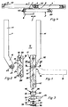
- a wing 2 In a fixed frame 1, a wing 2 can be set down in parallel and is displaceably mounted in the direction of the double arrow 3. In the closed position, it is located on the side of another wing or fixed field 4, in the same plane as this. Between the two is a central vertical beam 5 of the fixed frame 1. Depending on the fitting design, the sash 2 is transferred directly to the parallel storage position or after a previous tilting position. It has an inner handle 6 of a conventional type and an outer turning handle 7. As shown in FIG. 4 of the drawing, the two differ substantially in terms of their shape and thickness measured perpendicular to the wing plane.
- the outer twist grip 7 is extremely flat and flat and is so close to the wing plane that it is easily through the gap 8 between the left vertical spar 42 of the fixed Field 4 and the plane of the wing 2 can be pushed through.
- both handles extend approximately vertically upwards.
- the external twist grip 7 is of an angular or arcuate shape, the arc or angular outside pointing towards the central vertical spar 5 (FIG. 1).
- the one angle leg 11, ie the actual handle of the rotary handle 7, extends approximately vertically upward in the closed position, as is also the case with the inner handle and with straight outer rotary handles known per se.
- Its central axis is laterally offset in the direction of the arrow 12 from an imaginary plane through the central axis of symmetry 13 or through this axis and extending perpendicular to the plane of the drawing.
- the two angular angles 11 and 15 lie in a common plane running parallel to the plane of the wing 2.
- the handle emerges from an outlet opening 16 of a housing 17 which extends towards the central vertical spar 5.
- the housing 17 is formed by a base part 18 and a rosette 19.
- the base part 18 is placed on the outer surface 20 of the wing 2.
- the rotary handle 7 is then mounted and finally the rosette 19.
- the handle has a receptacle 21 for the axis of rotation 14.
- the axis of rotation usually consists of a square in such handles, which is non-rotatably connected to the inner handle 6. Accordingly, the receptacle 21 also has a square or square cross section.
- the base part 18 is formed as a mirror image of a horizontal plane 24 placed through the central axis 24 and extending perpendicular to the sheet plane. In this respect, this handle can be used for both right and left hinges.
- the rotary handle 7 is mirror image of a vertical plane through the dash-dotted line 25. It is simply turned through 180 ° for the other type of stop.
- the base part 18 is in accordance with the representations according to FIGS. 1 and 2 rotated by 180 °. Its base plate 26 lies against the outer surface 20 in every type of stop.
- the base part 18 has a central through hole 27 and two through bores 28 and 29 which are spaced apart from it at the same distance.
- two essentially obliquely extending webs which form stops 30 and 31 for the rotary handle 7.
- the lower stop 30 limits the rotational movement downwards. It is used as a top stop for a different type of stop.
- the two inclined webs merge into a lateral web 32, which forms part of the housing wall.
- bearing eyes 33 and 34 protruding to opposite sides are formed on the rotary handle 7.
- the bearing eye 33 engages in the through hole 27 of the base part 18, while the bearing eye 34 is received by the bore of a bearing bush 35 which is mounted in a blind hole on the outer wall 36 of the rosette 19.
- the bearing bush is advantageously made of plastic.
- two peg-shaped centering lugs 37 and 38 are attached to the rosette 19, in particular molded on. Each is equipped with a blind hole thread 39, and it passes through the assigned through hole 28 or 29 of the base part 18. From the inside of the wing 2, fastening screws are screwed into the blind hole thread 39 of the centering lugs 37 and 38 and thereby the rosette 19 against the turning handle 7 drawn. At the same time with the handle, the base part 18 is thereby held. The free ends of the centering lugs 37 and 38, if they protrude beyond the through hole 27, can engage in bores in the associated vertical wing leg 40.
- an opening 41 is made, in particular at the lower end of the rosette 19, the shape of which corresponds to that of a locking cylinder to be inserted into the lock in question.
- the rosette is expediently made of metal, in particular aluminum or the like.
- the use of aluminum has the advantage that this material can be anodized, so that the color of the handle can be adapted to the other fittings.
- the base plate can preferably be made of plastic, for example as a molded part.
Landscapes
- Hinges (AREA)
- Electric Vacuum Cleaner (AREA)
- Lock And Its Accessories (AREA)
- Window Of Vehicle (AREA)
Claims (10)
Priority Applications (1)
| Application Number | Priority Date | Filing Date | Title |
|---|---|---|---|
| AT88102235T ATE53625T1 (de) | 1987-03-06 | 1988-02-16 | Aussen-drehgriff fuer einen wenigstens schiebbaren fluegel eines fensters, einer tuer od. dgl. |
Applications Claiming Priority (2)
| Application Number | Priority Date | Filing Date | Title |
|---|---|---|---|
| DE8703416U | 1987-03-06 | ||
| DE8703416U DE8703416U1 (de) | 1987-03-06 | 1987-03-06 | Außen-Drehgriff für einen wenigstens schiebbaren Flügel eines Fensters, einer Tür od.dgl. |
Publications (3)
| Publication Number | Publication Date |
|---|---|
| EP0287764A1 EP0287764A1 (fr) | 1988-10-26 |
| EP0287764B1 EP0287764B1 (fr) | 1990-06-13 |
| EP0287764B2 true EP0287764B2 (fr) | 1994-07-13 |
Family
ID=6805542
Family Applications (1)
| Application Number | Title | Priority Date | Filing Date |
|---|---|---|---|
| EP88102235A Expired - Lifetime EP0287764B2 (fr) | 1987-03-06 | 1988-02-16 | Poignée rotative extérieure, pour le battant coulissant d'une fenêtre, d'une porte ou similaire |
Country Status (3)
| Country | Link |
|---|---|
| EP (1) | EP0287764B2 (fr) |
| AT (1) | ATE53625T1 (fr) |
| DE (2) | DE8703416U1 (fr) |
Families Citing this family (1)
| Publication number | Priority date | Publication date | Assignee | Title |
|---|---|---|---|---|
| CN117071983A (zh) * | 2023-07-31 | 2023-11-17 | 福建天闽绿色建筑产业有限公司 | 一种外平开门窗的锁闭装置 |
Family Cites Families (4)
| Publication number | Priority date | Publication date | Assignee | Title |
|---|---|---|---|---|
| DE2538942A1 (de) * | 1975-09-02 | 1977-03-03 | Herbert Didczys | Abschliessbare hebelolive |
| DE2542326A1 (de) * | 1975-09-23 | 1977-03-24 | Herbert Didczys | Abschliessbare hebelolive |
| GB2105774B (en) * | 1979-01-23 | 1983-08-03 | Norcros Investments Ltd | Locking handles |
| GB2064639B (en) * | 1979-11-30 | 1983-06-08 | Securistyle Ltd | Window fasteners |
-
1987
- 1987-03-06 DE DE8703416U patent/DE8703416U1/de not_active Expired
-
1988
- 1988-02-16 EP EP88102235A patent/EP0287764B2/fr not_active Expired - Lifetime
- 1988-02-16 DE DE8888102235T patent/DE3860222D1/de not_active Expired - Lifetime
- 1988-02-16 AT AT88102235T patent/ATE53625T1/de not_active IP Right Cessation
Also Published As
| Publication number | Publication date |
|---|---|
| DE3860222D1 (de) | 1990-07-19 |
| EP0287764A1 (fr) | 1988-10-26 |
| DE8703416U1 (de) | 1987-04-16 |
| EP0287764B1 (fr) | 1990-06-13 |
| ATE53625T1 (de) | 1990-06-15 |
Similar Documents
| Publication | Publication Date | Title |
|---|---|---|
| EP0683296B1 (fr) | Système à ferrures positionnable automatique en partie pour fenêtres, portes ou similaires | |
| EP0492341B1 (fr) | Crémone pour fenêtre à deux volets, ou similaire | |
| EP0361001B1 (fr) | Serrure à crochet | |
| EP0231498B2 (fr) | Ferrure pour panneau de fenêtre, porte ou similaire pouvant au moins être basculé | |
| DE3844627A1 (de) | Mit verschlussmitteln ausgeruestetes fenster, tuer oder dergleichen | |
| EP0318422B1 (fr) | Charnière réglable, en particulier pour portes | |
| EP0652345B1 (fr) | Charnière réglable pour portes ou fenêtres | |
| EP0844348B1 (fr) | Penture pour portes ou fenêtres | |
| EP0287764B2 (fr) | Poignée rotative extérieure, pour le battant coulissant d'une fenêtre, d'une porte ou similaire | |
| DE9402161U1 (de) | Zusatzverriegelungsvorrichtung für ein Fenster, eine Tür o.dgl. mit einem wenigstens drehbarem Flügel | |
| EP0128372B1 (fr) | Dispositif de fermeture d'un battant d'une porte, fenêtre ou similaire à deux battants | |
| EP1197623A1 (fr) | Charnière | |
| DE3317264C2 (fr) | ||
| DE8413145U1 (de) | Beschlag fuer einen fluegel eines fensters, einer tuer od. dgl. | |
| EP0704593B1 (fr) | Ferrure pour battant pivotant, ou pivotant et basculant, de fenêtres, portes ou similaires avec pièce excentrique verrouillable pour regler la feuillure verticale et/ou la force de pression entre le vantail et le cadre fixe | |
| EP0275895B1 (fr) | Ferrure pour un panneau pouvant au moins basculer | |
| DE4200868A1 (de) | Zusatz-schliesseinrichtung fuer fenster | |
| DE8111079U1 (de) | Ecklager fuer fluegel von fenstern, tueren od. dgl. | |
| EP0667432B1 (fr) | Dispositif de verrouillage supplémentaire pour fenêtre ou similaires | |
| DE3445598C2 (fr) | ||
| DE3348356C2 (en) | Tilting window casement or door wing extending arm | |
| EP0616106B1 (fr) | Fenêtre ou porte avec ferrure de charnière | |
| DE2059185A1 (de) | Treibstangenverschluss fuer Tueren,Fenster od.dgl. | |
| DE19918283A1 (de) | Tür- oder Fensterdrehband | |
| DE4236431A1 (fr) |
Legal Events
| Date | Code | Title | Description |
|---|---|---|---|
| PUAI | Public reference made under article 153(3) epc to a published international application that has entered the european phase |
Free format text: ORIGINAL CODE: 0009012 |
|
| AK | Designated contracting states |
Kind code of ref document: A1 Designated state(s): AT CH DE FR GB LI |
|
| 17P | Request for examination filed |
Effective date: 19880914 |
|
| 17Q | First examination report despatched |
Effective date: 19891110 |
|
| GRAA | (expected) grant |
Free format text: ORIGINAL CODE: 0009210 |
|
| AK | Designated contracting states |
Kind code of ref document: B1 Designated state(s): AT CH DE FR GB LI |
|
| REF | Corresponds to: |
Ref document number: 53625 Country of ref document: AT Date of ref document: 19900615 Kind code of ref document: T |
|
| GBT | Gb: translation of ep patent filed (gb section 77(6)(a)/1977) | ||
| REF | Corresponds to: |
Ref document number: 3860222 Country of ref document: DE Date of ref document: 19900719 |
|
| ET | Fr: translation filed | ||
| PLBI | Opposition filed |
Free format text: ORIGINAL CODE: 0009260 |
|
| PLBI | Opposition filed |
Free format text: ORIGINAL CODE: 0009260 |
|
| 26 | Opposition filed |
Opponent name: SIEGENIA-FRANK KG Effective date: 19910129 |
|
| 26 | Opposition filed |
Opponent name: ROTO FRANK AKTIENGESELLSCHAFT Effective date: 19910311 Opponent name: SIEGENIA-FRANK KG Effective date: 19910129 |
|
| PUAA | Information related to the publication of a b2 document modified |
Free format text: ORIGINAL CODE: 0009299PMAP |
|
| PUAH | Patent maintained in amended form |
Free format text: ORIGINAL CODE: 0009272 |
|
| STAA | Information on the status of an ep patent application or granted ep patent |
Free format text: STATUS: PATENT MAINTAINED AS AMENDED |
|
| 27A | Patent maintained in amended form |
Effective date: 19940713 |
|
| AK | Designated contracting states |
Kind code of ref document: B2 Designated state(s): GB |
|
| REG | Reference to a national code |
Ref country code: CH Ref legal event code: AEN |
|
| R27A | Patent maintained in amended form (corrected) |
Effective date: 19940713 |
|
| ET3 | Fr: translation filed ** decision concerning opposition | ||
| GBTA | Gb: translation of amended ep patent filed (gb section 77(6)(b)/1977) |
Effective date: 19941229 |
|
| PGFP | Annual fee paid to national office [announced via postgrant information from national office to epo] |
Ref country code: GB Payment date: 19970113 Year of fee payment: 10 |
|
| PGFP | Annual fee paid to national office [announced via postgrant information from national office to epo] |
Ref country code: FR Payment date: 19970114 Year of fee payment: 10 |
|
| PGFP | Annual fee paid to national office [announced via postgrant information from national office to epo] |
Ref country code: AT Payment date: 19970128 Year of fee payment: 10 |
|
| PGFP | Annual fee paid to national office [announced via postgrant information from national office to epo] |
Ref country code: CH Payment date: 19970131 Year of fee payment: 10 |
|
| PG25 | Lapsed in a contracting state [announced via postgrant information from national office to epo] |
Ref country code: GB Free format text: LAPSE BECAUSE OF NON-PAYMENT OF DUE FEES Effective date: 19980216 Ref country code: AT Free format text: LAPSE BECAUSE OF NON-PAYMENT OF DUE FEES Effective date: 19980216 |
|
| PG25 | Lapsed in a contracting state [announced via postgrant information from national office to epo] |
Ref country code: LI Free format text: LAPSE BECAUSE OF NON-PAYMENT OF DUE FEES Effective date: 19980228 Ref country code: FR Free format text: THE PATENT HAS BEEN ANNULLED BY A DECISION OF A NATIONAL AUTHORITY Effective date: 19980228 Ref country code: CH Free format text: LAPSE BECAUSE OF NON-PAYMENT OF DUE FEES Effective date: 19980228 |
|
| GBPC | Gb: european patent ceased through non-payment of renewal fee |
Effective date: 19980216 |
|
| REG | Reference to a national code |
Ref country code: CH Ref legal event code: PL |
|
| REG | Reference to a national code |
Ref country code: FR Ref legal event code: ST |
|
| PGFP | Annual fee paid to national office [announced via postgrant information from national office to epo] |
Ref country code: DE Payment date: 20000122 Year of fee payment: 13 |
|
| PG25 | Lapsed in a contracting state [announced via postgrant information from national office to epo] |
Ref country code: DE Free format text: LAPSE BECAUSE OF NON-PAYMENT OF DUE FEES Effective date: 20011201 |