EP0287024A2 - Schlauchförmiges Förderband - Google Patents
Schlauchförmiges Förderband Download PDFInfo
- Publication number
- EP0287024A2 EP0287024A2 EP88105780A EP88105780A EP0287024A2 EP 0287024 A2 EP0287024 A2 EP 0287024A2 EP 88105780 A EP88105780 A EP 88105780A EP 88105780 A EP88105780 A EP 88105780A EP 0287024 A2 EP0287024 A2 EP 0287024A2
- Authority
- EP
- European Patent Office
- Prior art keywords
- belt
- tubular
- belt conveyor
- guide frames
- rolled
- Prior art date
- Legal status (The legal status is an assumption and is not a legal conclusion. Google has not performed a legal analysis and makes no representation as to the accuracy of the status listed.)
- Granted
Links
- 239000000463 material Substances 0.000 claims abstract description 15
- 239000008187 granular material Substances 0.000 abstract description 3
- 239000012254 powdered material Substances 0.000 abstract description 3
- 230000004048 modification Effects 0.000 description 2
- 238000012986 modification Methods 0.000 description 2
- 230000008859 change Effects 0.000 description 1
- 230000000694 effects Effects 0.000 description 1
- 239000004576 sand Substances 0.000 description 1
- 230000032258 transport Effects 0.000 description 1
Images


Classifications
-
- B—PERFORMING OPERATIONS; TRANSPORTING
- B65—CONVEYING; PACKING; STORING; HANDLING THIN OR FILAMENTARY MATERIAL
- B65G—TRANSPORT OR STORAGE DEVICES, e.g. CONVEYORS FOR LOADING OR TIPPING, SHOP CONVEYOR SYSTEMS OR PNEUMATIC TUBE CONVEYORS
- B65G15/00—Conveyors having endless load-conveying surfaces, i.e. belts and like continuous members, to which tractive effort is transmitted by means other than endless driving elements of similar configuration
- B65G15/08—Conveyors having endless load-conveying surfaces, i.e. belts and like continuous members, to which tractive effort is transmitted by means other than endless driving elements of similar configuration the load-carrying surface being formed by a concave or tubular belt, e.g. a belt forming a trough
-
- B—PERFORMING OPERATIONS; TRANSPORTING
- B65—CONVEYING; PACKING; STORING; HANDLING THIN OR FILAMENTARY MATERIAL
- B65G—TRANSPORT OR STORAGE DEVICES, e.g. CONVEYORS FOR LOADING OR TIPPING, SHOP CONVEYOR SYSTEMS OR PNEUMATIC TUBE CONVEYORS
- B65G39/00—Rollers, e.g. drive rollers, or arrangements thereof incorporated in roller-ways or other types of mechanical conveyors
- B65G39/10—Arrangements of rollers
- B65G39/12—Arrangements of rollers mounted on framework
-
- B—PERFORMING OPERATIONS; TRANSPORTING
- B65—CONVEYING; PACKING; STORING; HANDLING THIN OR FILAMENTARY MATERIAL
- B65G—TRANSPORT OR STORAGE DEVICES, e.g. CONVEYORS FOR LOADING OR TIPPING, SHOP CONVEYOR SYSTEMS OR PNEUMATIC TUBE CONVEYORS
- B65G2201/00—Indexing codes relating to handling devices, e.g. conveyors, characterised by the type of product or load being conveyed or handled
- B65G2201/04—Bulk
Definitions
- the present invention relates to a tubular belt conveyor for transporting powdered or granular material and especially to a tubular belt conveyor which is adapted to convey material such as a long piece smoothly.
- an endless conveyor belt 1 is wound at its flattened ends around a front end roller 2 and a rear end roller 3 to circulate, and passes through a plurality of guide frames 5, 6 and 7 in which a plurality of guide rollers 4 are arranged in a circle so that the belt may be rolled up into tubular form in which material 8 to be conveyed is wrapped for transportation.
- the intermediate frame 6 is divided into two chambers, an upper chamber 6a and a lower chamber 6c, each comprising an opening 6a through which the conveyor belt 1 passes and the guide rollers 4 which surround the opening 6a in a circle.
- An outgoing path 1a and a return path 1b pass through the openings 6a and 6a of the upper and lower chambers 6b and 6c respectively so that each path is maintained in tubular form.
- guide frames 5 comprising a first guide frame 5-1, a second guide frame 5-2 and a third guide frame 5-3 at a proper interval on a horizontal frame 9 located between the outgoing and return paths 1a and 1b.
- each guide frame 5-1, 5-2 and 5-3 comprises a hexagonal frame 11 having an opening 10 at the center, and there are provided a plurality of guide rollers 4, such as six, in a circle to surround the opening 10.
- each guide frames 5-1, 5-2 and 5-3 are the same gradually-reduced forms, so that the outgoing path 1a passing through each opening 10 is gradually rolled up from flattened form to come into the guide frame 6.
- X-4 is a circle inscribed in each guide roller 4 of the guide frame 5, and l4 is its diameter.
- Three guide frames 7 disposed between the front end roller 2 and the nearest guide frame 6 comprises a first guide frame 7-1, a second guide frame 7-2 and a third guide frame 7-3 having the same structure as the first, second and third guide frames 5-1, 5-2 and 5-3.
- the beginning end of the return path 1b passing through the guide frames 7-1, 7-2 and 7-3, the flattened return path 1b which circulates around the front end roller 2 is rolled up gradually into tubular form which runs through the lower chamber 6c of the guide frame 6.
- a frame 12 is provided for supporting each guide frame 7-1, 7-2 and 7-3 and is similar to the frame 9.
- a hopper 13 for feeding the material 8 to be conveyed onto the outgoing path 1a above the beginning end of the outgoing path 1a near the rear end roller 3 and a receiver 13 around the front end roller 2.
- the front end roller 2 and/or rear end roller 3 rotates in clockwise direction in Fig. 8 by suitable drive means (not shown), whereby the conveyor belt 1 rotates as shown by arrows in Fig. 8 and is gradually rolled up into tubular form through the guide frame 5, wrapping the conveyed material 8 which is fed from the hopper 13.
- the above-mentioned tubular belt conveyor transports the material in a tube.
- the conveyed material includes a long piece 8a (in Fig. 10) such as a wooden piece longer than the inner diameter of the tubular portion of the conveyor belt 1 when it transfers earth and sand from reclaimed land, the long piece 8a perpendicular to the running direction of the conveyor belt 1 is transported and bumps against the walls of the conveyor belt 1 which is being rolled up, so that it is disadvantageous to damage a tublar wall of the belt 1 or result in interruption of its running.
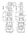
- Figs. 1 to 5 illustrate a first embodiment of the present invention, in which the numerals identify parts identical with in the prior art described above and the details will be omitted.
- the second emboiment which will be described thereinafter is as well.
- the third guide frame 5-3 is disposed by placing its center O at a distance D laterally away from the axis L of a conveyor belt 1, so that there are provided a parallel portion which is parallel to the axis L and an inclined portion which is not parallel thereto, one portion being alternate with the other, at the one side of the belt 1 which is rolled up gradually, while there are provided an inclined portion 19 and a parellel portion 20 which is parallel to the axis L at the other side wall 18 opposite to the inclined portion 17.
- the conveyor belt 1 transfers the long piece 8a which is almost as long as a distance between the inclined and parallel portions 17 and 20, with other material, its length being disposed in the radial direction of the belt. Then, one end of the long piece 8 bumps against the inclined portion 17 of the side wall 15, while, with movement of other conveyed material 8, the other end of the long piece 8 rotates forwardly around the one end to reduce an angle to the axis L to less than 90°.
- the other end of the long piece 8a bumps against the inclined portion 19 at the side wall 18; however, the long piece 8a is disposed at considerably less than 90° to the axis so that the long piece 8a runs forwardly with the other material 8 without hindering by the inclined portion 19 to reduce the oblique angle thereof further.
- Fig. 6 illustrates a second embodiment of the present invention.
- the third guide frame 5-3 is disposed such that its center is laterally away from the axis L at a distance D and the second guide frame 5-2 is arranged such that its center O is laterally away from the axis L at a distance D in the opposite direction, whereby there is formed an inclined portion 21 which expands in a running direction of the conveyor belt 1 at the side wall 18 ⁇ of the belt 1 and the other is similar to the above.
- the second embodiment attains functions and effects similar to those in the first embodiment.
- any of the guide frames 6 may be arranged by placing their centers laterally away from the axis L.
- the above embodiments illustrate a tubular belt conveyor which is rolled up by overlapping the opposed edges of a belt, but as shown in Fig. 7, the present invention may be also adapted to a tubular belt conveyor which is rolled up by bringing the opposed longitudinal edges of a belt into abutment or contacting or approaching the edges.
- the present invention provides decrease of possibility that a long piece included in the conveyed material bumps against the conveyor belt which is being rolled up gradually or has been rolled up, whereby it is prevented for the material to block in the belt, damage the wall or interrupt the running of the belt.
Landscapes
- Engineering & Computer Science (AREA)
- Mechanical Engineering (AREA)
- Structure Of Belt Conveyors (AREA)
- Belt Conveyors (AREA)
- Fish Paste Products (AREA)
Priority Applications (1)
| Application Number | Priority Date | Filing Date | Title |
|---|---|---|---|
| AT88105780T ATE72198T1 (de) | 1987-04-16 | 1988-04-12 | Schlauchfoermiges foerderband. |
Applications Claiming Priority (2)
| Application Number | Priority Date | Filing Date | Title |
|---|---|---|---|
| JP91870/87 | 1987-04-16 | ||
| JP62091870A JP2523315B2 (ja) | 1987-04-16 | 1987-04-16 | パイプコンベヤ |
Publications (3)
| Publication Number | Publication Date |
|---|---|
| EP0287024A2 true EP0287024A2 (de) | 1988-10-19 |
| EP0287024A3 EP0287024A3 (en) | 1989-03-22 |
| EP0287024B1 EP0287024B1 (de) | 1992-01-29 |
Family
ID=14038593
Family Applications (1)
| Application Number | Title | Priority Date | Filing Date |
|---|---|---|---|
| EP88105780A Expired - Lifetime EP0287024B1 (de) | 1987-04-16 | 1988-04-12 | Schlauchförmiges Förderband |
Country Status (5)
| Country | Link |
|---|---|
| EP (1) | EP0287024B1 (de) |
| JP (1) | JP2523315B2 (de) |
| AT (1) | ATE72198T1 (de) |
| DE (1) | DE3868115D1 (de) |
| ZA (1) | ZA882650B (de) |
Cited By (9)
| Publication number | Priority date | Publication date | Assignee | Title |
|---|---|---|---|---|
| DE8915255U1 (de) * | 1989-12-29 | 1991-05-02 | VSR Engineering GmbH Fördertechnik, 4330 Mülheim | Rolleneinrichtung für Schlauchgurtförderer u.dgl. |
| DE4201309A1 (de) * | 1991-01-23 | 1992-07-30 | Vsr Eng Foerdertechnik | Schlauchgurtfoerderbandvorrichtung |
| RU2328432C1 (ru) * | 2007-01-16 | 2008-07-10 | Государственное образовательное учреждение высшего профессионального образования "Санкт-Петербургский государственный горный институт им. Г.В. Плеханова (технический университет)" | Трубчатый ленточный конвейер |
| RU2328431C1 (ru) * | 2006-12-21 | 2008-07-10 | Государственное образовательное учреждение высшего профессионального образования "Санкт-Петербургский государственный горный институт им. Г.В. Плеханова (технический университет)" | Трубчатый ленточный конвейер |
| RU2329933C1 (ru) * | 2007-01-10 | 2008-07-27 | Государственное образовательное учреждение высшего профессионального образования "Санкт-Петербургский государственный горный институт имения Г.В. Плеханова (технический университет) | Трубчатый ленточный конвейер |
| RU2329931C1 (ru) * | 2006-12-08 | 2008-07-27 | Государственное образовательное учреждение высшего профессионального образования "Санкт-Петербургский государственный горный институт имени Г.В. Плеханова (технический университет)" | Трубчатый ленточный конвейер |
| RU2329932C1 (ru) * | 2006-12-13 | 2008-07-27 | Государственное образовательное учреждение высшего профессионального образования "Санкт-Петербургский государственный институт имени Г.В. Плеханова (технический университет)" | Ленточный трубчатый конвейер |
| CN109292362A (zh) * | 2018-10-15 | 2019-02-01 | 江苏环宇起重运输机械有限责任公司 | 带安全报警制动的管带机 |
| CN112722687A (zh) * | 2021-01-08 | 2021-04-30 | 辽宁工程技术大学 | 一种轮轨管状带式输送机 |
Families Citing this family (1)
| Publication number | Priority date | Publication date | Assignee | Title |
|---|---|---|---|---|
| JP2010095344A (ja) * | 2008-10-16 | 2010-04-30 | Tokuyama Corp | パイプコンベア |
Family Cites Families (3)
| Publication number | Priority date | Publication date | Assignee | Title |
|---|---|---|---|---|
| JPS5574905A (en) * | 1978-11-28 | 1980-06-05 | Kunio Hashimoto | Carrying method and equipment for powder material |
| CA1169802A (en) * | 1981-02-18 | 1984-06-26 | Kunio Hashimoto | Method and device for preventing a flexible tubular belt from twisting for use in a tubular belt conveyer |
| DE3404186C2 (de) * | 1984-02-07 | 1985-08-29 | Götz Dipl.-Ing. 7129 Ilsfeld Thomas | Kurvengängiger Bandförderer |
-
1987
- 1987-04-16 JP JP62091870A patent/JP2523315B2/ja not_active Expired - Lifetime
-
1988
- 1988-04-12 AT AT88105780T patent/ATE72198T1/de not_active IP Right Cessation
- 1988-04-12 DE DE8888105780T patent/DE3868115D1/de not_active Expired - Fee Related
- 1988-04-12 EP EP88105780A patent/EP0287024B1/de not_active Expired - Lifetime
- 1988-04-15 ZA ZA882650A patent/ZA882650B/xx unknown
Cited By (10)
| Publication number | Priority date | Publication date | Assignee | Title |
|---|---|---|---|---|
| DE8915255U1 (de) * | 1989-12-29 | 1991-05-02 | VSR Engineering GmbH Fördertechnik, 4330 Mülheim | Rolleneinrichtung für Schlauchgurtförderer u.dgl. |
| DE4201309A1 (de) * | 1991-01-23 | 1992-07-30 | Vsr Eng Foerdertechnik | Schlauchgurtfoerderbandvorrichtung |
| RU2329931C1 (ru) * | 2006-12-08 | 2008-07-27 | Государственное образовательное учреждение высшего профессионального образования "Санкт-Петербургский государственный горный институт имени Г.В. Плеханова (технический университет)" | Трубчатый ленточный конвейер |
| RU2329932C1 (ru) * | 2006-12-13 | 2008-07-27 | Государственное образовательное учреждение высшего профессионального образования "Санкт-Петербургский государственный институт имени Г.В. Плеханова (технический университет)" | Ленточный трубчатый конвейер |
| RU2328431C1 (ru) * | 2006-12-21 | 2008-07-10 | Государственное образовательное учреждение высшего профессионального образования "Санкт-Петербургский государственный горный институт им. Г.В. Плеханова (технический университет)" | Трубчатый ленточный конвейер |
| RU2329933C1 (ru) * | 2007-01-10 | 2008-07-27 | Государственное образовательное учреждение высшего профессионального образования "Санкт-Петербургский государственный горный институт имения Г.В. Плеханова (технический университет) | Трубчатый ленточный конвейер |
| RU2328432C1 (ru) * | 2007-01-16 | 2008-07-10 | Государственное образовательное учреждение высшего профессионального образования "Санкт-Петербургский государственный горный институт им. Г.В. Плеханова (технический университет)" | Трубчатый ленточный конвейер |
| CN109292362A (zh) * | 2018-10-15 | 2019-02-01 | 江苏环宇起重运输机械有限责任公司 | 带安全报警制动的管带机 |
| CN112722687A (zh) * | 2021-01-08 | 2021-04-30 | 辽宁工程技术大学 | 一种轮轨管状带式输送机 |
| CN112722687B (zh) * | 2021-01-08 | 2022-05-20 | 辽宁工程技术大学 | 一种轮轨管状带式输送机 |
Also Published As
| Publication number | Publication date |
|---|---|
| JP2523315B2 (ja) | 1996-08-07 |
| EP0287024A3 (en) | 1989-03-22 |
| ZA882650B (en) | 1988-10-13 |
| ATE72198T1 (de) | 1992-02-15 |
| EP0287024B1 (de) | 1992-01-29 |
| JPS63262316A (ja) | 1988-10-28 |
| DE3868115D1 (de) | 1992-03-12 |
Similar Documents
| Publication | Publication Date | Title |
|---|---|---|
| EP0287024B1 (de) | Schlauchförmiges Förderband | |
| US5695042A (en) | Conveyor | |
| US4406359A (en) | Method and apparatus for mass transit of cylindrical articles between differing elevations | |
| NO903236D0 (no) | Innretning og fremgangsmaate for dekking av et naeringsmiddel med granulert materiale. | |
| EP0704392B1 (de) | Kipper für Rollengepäck | |
| ITBO930058A1 (it) | Metodo e trasportatore per il cambio formato automatico nei trasportatori a cassetti a percorso ad anello chiuso aventi singoli cassetti di trasporto comprendenti una coppia di pareti definenti il _formato | |
| US4778046A (en) | Belt conveyor | |
| JPS63262319A (ja) | パイプコンベヤにおけるベルト案内装置 | |
| JPS58104807A (ja) | パイプコンベヤによる往復搬送方法及び往復搬送式パイプコンベヤ装置 | |
| JP2000327121A (ja) | カーブ部を有するパイプコンベヤのねじれ防止方法及びその装置 | |
| JPS6274813A (ja) | パイプコンベアにおける搬送ベルトの捩れ防止装置 | |
| JPS6133406A (ja) | パイプコンベヤ | |
| JP2630927B2 (ja) | パイプコンベヤにおける被搬送物供給用シュート | |
| JPH083370Y2 (ja) | 復路において搬送面を隠蔽するようにした平ベルトコンベヤ | |
| JPH0680238A (ja) | 反転装置 | |
| KR200155669Y1 (ko) | 벨트 컨베이어의 뒤집힘 방지장치 | |
| JPH07285630A (ja) | 搬送コンベア | |
| JPH09169413A (ja) | 包み込み型ベルトコンベヤ | |
| JP2001315929A (ja) | ループ式ベルトコンベヤ装置 | |
| KR19980064923U (ko) | 벨트 콘베이어의 사행방지용 롤러 | |
| JP2004026490A (ja) | 搬送物の合流装置 | |
| JPS62215412A (ja) | ベルトコンベヤ | |
| JPS59143804A (ja) | 鋼管の繰送り装置 | |
| HK1013977B (en) | Wheeled luggage tipper | |
| JP2000095317A (ja) | パイプコンベヤ |
Legal Events
| Date | Code | Title | Description |
|---|---|---|---|
| PUAI | Public reference made under article 153(3) epc to a published international application that has entered the european phase |
Free format text: ORIGINAL CODE: 0009012 |
|
| AK | Designated contracting states |
Kind code of ref document: A2 Designated state(s): AT DE FR IT |
|
| PUAL | Search report despatched |
Free format text: ORIGINAL CODE: 0009013 |
|
| AK | Designated contracting states |
Kind code of ref document: A3 Designated state(s): AT DE FR IT |
|
| 17P | Request for examination filed |
Effective date: 19890530 |
|
| 17Q | First examination report despatched |
Effective date: 19910628 |
|
| GRAA | (expected) grant |
Free format text: ORIGINAL CODE: 0009210 |
|
| AK | Designated contracting states |
Kind code of ref document: B1 Designated state(s): AT DE FR IT |
|
| REF | Corresponds to: |
Ref document number: 72198 Country of ref document: AT Date of ref document: 19920215 Kind code of ref document: T |
|
| REF | Corresponds to: |
Ref document number: 3868115 Country of ref document: DE Date of ref document: 19920312 |
|
| ITF | It: translation for a ep patent filed | ||
| ET | Fr: translation filed | ||
| PLBE | No opposition filed within time limit |
Free format text: ORIGINAL CODE: 0009261 |
|
| STAA | Information on the status of an ep patent application or granted ep patent |
Free format text: STATUS: NO OPPOSITION FILED WITHIN TIME LIMIT |
|
| 26N | No opposition filed | ||
| PGFP | Annual fee paid to national office [announced via postgrant information from national office to epo] |
Ref country code: DE Payment date: 20000410 Year of fee payment: 13 |
|
| PGFP | Annual fee paid to national office [announced via postgrant information from national office to epo] |
Ref country code: FR Payment date: 20000411 Year of fee payment: 13 |
|
| PGFP | Annual fee paid to national office [announced via postgrant information from national office to epo] |
Ref country code: AT Payment date: 20000412 Year of fee payment: 13 |
|
| PG25 | Lapsed in a contracting state [announced via postgrant information from national office to epo] |
Ref country code: AT Free format text: LAPSE BECAUSE OF NON-PAYMENT OF DUE FEES Effective date: 20010412 |
|
| PG25 | Lapsed in a contracting state [announced via postgrant information from national office to epo] |
Ref country code: FR Free format text: THE PATENT HAS BEEN ANNULLED BY A DECISION OF A NATIONAL AUTHORITY Effective date: 20010430 |
|
| PG25 | Lapsed in a contracting state [announced via postgrant information from national office to epo] |
Ref country code: DE Free format text: LAPSE BECAUSE OF NON-PAYMENT OF DUE FEES Effective date: 20020201 |
|
| REG | Reference to a national code |
Ref country code: FR Ref legal event code: ST |
|
| PGFP | Annual fee paid to national office [announced via postgrant information from national office to epo] |
Ref country code: IT Payment date: 20070622 Year of fee payment: 20 |