EP0287024A2 - A tubular belt conveyor - Google Patents
A tubular belt conveyor Download PDFInfo
- Publication number
- EP0287024A2 EP0287024A2 EP88105780A EP88105780A EP0287024A2 EP 0287024 A2 EP0287024 A2 EP 0287024A2 EP 88105780 A EP88105780 A EP 88105780A EP 88105780 A EP88105780 A EP 88105780A EP 0287024 A2 EP0287024 A2 EP 0287024A2
- Authority
- EP
- European Patent Office
- Prior art keywords
- belt
- tubular
- belt conveyor
- guide frames
- rolled
- Prior art date
- Legal status (The legal status is an assumption and is not a legal conclusion. Google has not performed a legal analysis and makes no representation as to the accuracy of the status listed.)
- Granted
Links
Images


Classifications
-
- B—PERFORMING OPERATIONS; TRANSPORTING
- B65—CONVEYING; PACKING; STORING; HANDLING THIN OR FILAMENTARY MATERIAL
- B65G—TRANSPORT OR STORAGE DEVICES, e.g. CONVEYORS FOR LOADING OR TIPPING, SHOP CONVEYOR SYSTEMS OR PNEUMATIC TUBE CONVEYORS
- B65G15/00—Conveyors having endless load-conveying surfaces, i.e. belts and like continuous members, to which tractive effort is transmitted by means other than endless driving elements of similar configuration
- B65G15/08—Conveyors having endless load-conveying surfaces, i.e. belts and like continuous members, to which tractive effort is transmitted by means other than endless driving elements of similar configuration the load-carrying surface being formed by a concave or tubular belt, e.g. a belt forming a trough
-
- B—PERFORMING OPERATIONS; TRANSPORTING
- B65—CONVEYING; PACKING; STORING; HANDLING THIN OR FILAMENTARY MATERIAL
- B65G—TRANSPORT OR STORAGE DEVICES, e.g. CONVEYORS FOR LOADING OR TIPPING, SHOP CONVEYOR SYSTEMS OR PNEUMATIC TUBE CONVEYORS
- B65G39/00—Rollers, e.g. drive rollers, or arrangements thereof incorporated in roller-ways or other types of mechanical conveyors
- B65G39/10—Arrangements of rollers
- B65G39/12—Arrangements of rollers mounted on framework
-
- B—PERFORMING OPERATIONS; TRANSPORTING
- B65—CONVEYING; PACKING; STORING; HANDLING THIN OR FILAMENTARY MATERIAL
- B65G—TRANSPORT OR STORAGE DEVICES, e.g. CONVEYORS FOR LOADING OR TIPPING, SHOP CONVEYOR SYSTEMS OR PNEUMATIC TUBE CONVEYORS
- B65G2201/00—Indexing codes relating to handling devices, e.g. conveyors, characterised by the type of product or load being conveyed or handled
- B65G2201/04—Bulk
Definitions
- the present invention relates to a tubular belt conveyor for transporting powdered or granular material and especially to a tubular belt conveyor which is adapted to convey material such as a long piece smoothly.
- an endless conveyor belt 1 is wound at its flattened ends around a front end roller 2 and a rear end roller 3 to circulate, and passes through a plurality of guide frames 5, 6 and 7 in which a plurality of guide rollers 4 are arranged in a circle so that the belt may be rolled up into tubular form in which material 8 to be conveyed is wrapped for transportation.
- the intermediate frame 6 is divided into two chambers, an upper chamber 6a and a lower chamber 6c, each comprising an opening 6a through which the conveyor belt 1 passes and the guide rollers 4 which surround the opening 6a in a circle.
- An outgoing path 1a and a return path 1b pass through the openings 6a and 6a of the upper and lower chambers 6b and 6c respectively so that each path is maintained in tubular form.
- guide frames 5 comprising a first guide frame 5-1, a second guide frame 5-2 and a third guide frame 5-3 at a proper interval on a horizontal frame 9 located between the outgoing and return paths 1a and 1b.
- each guide frame 5-1, 5-2 and 5-3 comprises a hexagonal frame 11 having an opening 10 at the center, and there are provided a plurality of guide rollers 4, such as six, in a circle to surround the opening 10.
- each guide frames 5-1, 5-2 and 5-3 are the same gradually-reduced forms, so that the outgoing path 1a passing through each opening 10 is gradually rolled up from flattened form to come into the guide frame 6.
- X-4 is a circle inscribed in each guide roller 4 of the guide frame 5, and l4 is its diameter.
- Three guide frames 7 disposed between the front end roller 2 and the nearest guide frame 6 comprises a first guide frame 7-1, a second guide frame 7-2 and a third guide frame 7-3 having the same structure as the first, second and third guide frames 5-1, 5-2 and 5-3.
- the beginning end of the return path 1b passing through the guide frames 7-1, 7-2 and 7-3, the flattened return path 1b which circulates around the front end roller 2 is rolled up gradually into tubular form which runs through the lower chamber 6c of the guide frame 6.
- a frame 12 is provided for supporting each guide frame 7-1, 7-2 and 7-3 and is similar to the frame 9.
- a hopper 13 for feeding the material 8 to be conveyed onto the outgoing path 1a above the beginning end of the outgoing path 1a near the rear end roller 3 and a receiver 13 around the front end roller 2.
- the front end roller 2 and/or rear end roller 3 rotates in clockwise direction in Fig. 8 by suitable drive means (not shown), whereby the conveyor belt 1 rotates as shown by arrows in Fig. 8 and is gradually rolled up into tubular form through the guide frame 5, wrapping the conveyed material 8 which is fed from the hopper 13.
- the above-mentioned tubular belt conveyor transports the material in a tube.
- the conveyed material includes a long piece 8a (in Fig. 10) such as a wooden piece longer than the inner diameter of the tubular portion of the conveyor belt 1 when it transfers earth and sand from reclaimed land, the long piece 8a perpendicular to the running direction of the conveyor belt 1 is transported and bumps against the walls of the conveyor belt 1 which is being rolled up, so that it is disadvantageous to damage a tublar wall of the belt 1 or result in interruption of its running.
- Figs. 1 to 5 illustrate a first embodiment of the present invention, in which the numerals identify parts identical with in the prior art described above and the details will be omitted.
- the second emboiment which will be described thereinafter is as well.
- the third guide frame 5-3 is disposed by placing its center O at a distance D laterally away from the axis L of a conveyor belt 1, so that there are provided a parallel portion which is parallel to the axis L and an inclined portion which is not parallel thereto, one portion being alternate with the other, at the one side of the belt 1 which is rolled up gradually, while there are provided an inclined portion 19 and a parellel portion 20 which is parallel to the axis L at the other side wall 18 opposite to the inclined portion 17.
- the conveyor belt 1 transfers the long piece 8a which is almost as long as a distance between the inclined and parallel portions 17 and 20, with other material, its length being disposed in the radial direction of the belt. Then, one end of the long piece 8 bumps against the inclined portion 17 of the side wall 15, while, with movement of other conveyed material 8, the other end of the long piece 8 rotates forwardly around the one end to reduce an angle to the axis L to less than 90°.
- the other end of the long piece 8a bumps against the inclined portion 19 at the side wall 18; however, the long piece 8a is disposed at considerably less than 90° to the axis so that the long piece 8a runs forwardly with the other material 8 without hindering by the inclined portion 19 to reduce the oblique angle thereof further.
- Fig. 6 illustrates a second embodiment of the present invention.
- the third guide frame 5-3 is disposed such that its center is laterally away from the axis L at a distance D and the second guide frame 5-2 is arranged such that its center O is laterally away from the axis L at a distance D in the opposite direction, whereby there is formed an inclined portion 21 which expands in a running direction of the conveyor belt 1 at the side wall 18 ⁇ of the belt 1 and the other is similar to the above.
- the second embodiment attains functions and effects similar to those in the first embodiment.
- any of the guide frames 6 may be arranged by placing their centers laterally away from the axis L.
- the above embodiments illustrate a tubular belt conveyor which is rolled up by overlapping the opposed edges of a belt, but as shown in Fig. 7, the present invention may be also adapted to a tubular belt conveyor which is rolled up by bringing the opposed longitudinal edges of a belt into abutment or contacting or approaching the edges.
- the present invention provides decrease of possibility that a long piece included in the conveyed material bumps against the conveyor belt which is being rolled up gradually or has been rolled up, whereby it is prevented for the material to block in the belt, damage the wall or interrupt the running of the belt.
Abstract
Description
- The present invention relates to a tubular belt conveyor for transporting powdered or granular material and especially to a tubular belt conveyor which is adapted to convey material such as a long piece smoothly.
- US Patents Nos.3,338,383 and 4,402,395 issued to Hashimoto disclose a known tubular belt conveyor in which a flat belt is rolled up into tubular form which conveys powdered or granular material without scattering.
- According to Figs. 8 and 11, the known tubular conveyor will be described in detail.
- In this known tubular belt conveyor, an
endless conveyor belt 1 is wound at its flattened ends around afront end roller 2 and arear end roller 3 to circulate, and passes through a plurality ofguide frames guide rollers 4 are arranged in a circle so that the belt may be rolled up into tubular form in whichmaterial 8 to be conveyed is wrapped for transportation. - As shown in Fig. 9, the
intermediate frame 6 is divided into two chambers, anupper chamber 6a and alower chamber 6c, each comprising anopening 6a through which theconveyor belt 1 passes and theguide rollers 4 which surround the opening 6a in a circle. Anoutgoing path 1a and areturn path 1b pass through theopenings lower chambers rear end roller 3 and the mostadjacent guide frame 6, there are threeguide frames 5 comprising a first guide frame 5-1, a second guide frame 5-2 and a third guide frame 5-3 at a proper interval on ahorizontal frame 9 located between the outgoing andreturn paths - As shown in Fig. 11, each guide frame 5-1, 5-2 and 5-3 comprises a
hexagonal frame 11 having anopening 10 at the center, and there are provided a plurality ofguide rollers 4, such as six, in a circle to surround theopening 10. In order to reduce the diameters ℓ1, ℓ2 and ℓ3 of the inscribed circles X-1, X-2 and X-3 which are formed by a plurality of guide rollers arranged in a circle, gradually in the running direction of theoutgoing path 1a, each guide frames 5-1, 5-2 and 5-3 are the same gradually-reduced forms, so that theoutgoing path 1a passing through eachopening 10 is gradually rolled up from flattened form to come into theguide frame 6. X-4 is a circle inscribed in eachguide roller 4 of theguide frame 5, and ℓ4 is its diameter. - Three guide frames 7 disposed between the
front end roller 2 and thenearest guide frame 6 comprises a first guide frame 7-1, a second guide frame 7-2 and a third guide frame 7-3 having the same structure as the first, second and third guide frames 5-1, 5-2 and 5-3. The beginning end of thereturn path 1b passing through the guide frames 7-1, 7-2 and 7-3, theflattened return path 1b which circulates around thefront end roller 2 is rolled up gradually into tubular form which runs through thelower chamber 6c of theguide frame 6. - A
frame 12 is provided for supporting each guide frame 7-1, 7-2 and 7-3 and is similar to theframe 9. There are provided ahopper 13 for feeding thematerial 8 to be conveyed onto theoutgoing path 1a above the beginning end of theoutgoing path 1a near therear end roller 3 and areceiver 13 around thefront end roller 2. Thefront end roller 2 and/orrear end roller 3 rotates in clockwise direction in Fig. 8 by suitable drive means (not shown), whereby theconveyor belt 1 rotates as shown by arrows in Fig. 8 and is gradually rolled up into tubular form through theguide frame 5, wrapping the conveyedmaterial 8 which is fed from thehopper 13. - When the
conveyor belt 1 passes through theupper opening 6a in eachguide frame 6 and rotates around thefront end roller 2, it opens so that the conveyed material falls down onto thereceiver 14 and is rolled up again into tubular form when it passes through the guide frames 7, whereby it passes through thelower opening 6a of eachguide frame 6 and circulates about therear end roller 3. - The above-mentioned tubular belt conveyor transports the material in a tube. If the conveyed material includes a
long piece 8a (in Fig. 10) such as a wooden piece longer than the inner diameter of the tubular portion of theconveyor belt 1 when it transfers earth and sand from reclaimed land, thelong piece 8a perpendicular to the running direction of theconveyor belt 1 is transported and bumps against the walls of theconveyor belt 1 which is being rolled up, so that it is disadvantageous to damage a tublar wall of thebelt 1 or result in interruption of its running. - It is therefore a primary object to provide a tubular belt conveyor in which conveyed material such as a long wooden piece is smoothly transported without bumping against the tubular wall so as to prevent the belt from subjecting to damage or interruption of running.
- This and other objects as well as advantages of the present invention will become clear by the following description of preferred embodiments of the invention with reference to the accompanying drawings, wherein:
- Fig. 1 is a transverse sectional plan view of an outgoing path in a first embodiment of a tubular belt conveyor according to the present invention;
- Fig. 2 is a side view of the same;
- Fig. 3 is a vertical sectional front view taken along line A-A;
- Figs. 4 and 5 are schematic transverse plan views of the main part exhibitting different functions respectively;
- Fig. 6 is a transverse sectional plan view of an outgoing path in a second embodiment of a tubular belt conveyor according to the present invention;
- Fig. 7 is a vertical sectional view of another embodiment of a conveyor belt of a tubular belt conveyor to which the present invention is adapted;
- Fig. 8 is a schematic side view of a known tubular belt conveyor;
- Fig. 9 is an enlarged sectional view taken along line B-B;
- Fig. 10 is a transverse sectional plan view of a known tubular belt conveyor shown in Fig. 8 and similar to Fig. 1; and
- Fig. 11 is an enlarged sectional view taken along line C-C in Fig. 8.
- Figs. 1 to 5 illustrate a first embodiment of the present invention, in which the numerals identify parts identical with in the prior art described above and the details will be omitted. The second emboiment which will be described thereinafter is as well.
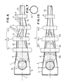
- In the first embodiment, in three guide frames 5-1, 5-2 and 5-3 at the beginning end of an
outgoing path 1a, only the third guide frame 5-3 is disposed by placing its center O at a distance D laterally away from the axis L of aconveyor belt 1, so that there are provided a parallel portion which is parallel to the axis L and an inclined portion which is not parallel thereto, one portion being alternate with the other, at the one side of thebelt 1 which is rolled up gradually, while there are provided aninclined portion 19 and aparellel portion 20 which is parallel to the axis L at theother side wall 18 opposite to theinclined portion 17. - As shown by dotted lines in Fig. 4, the
conveyor belt 1 transfers thelong piece 8a which is almost as long as a distance between the inclined andparallel portions long piece 8 bumps against theinclined portion 17 of theside wall 15, while, with movement of other conveyedmaterial 8, the other end of thelong piece 8 rotates forwardly around the one end to reduce an angle to the axis L to less than 90°. - Further, the other end of the
long piece 8a bumps against theinclined portion 19 at theside wall 18; however, thelong piece 8a is disposed at considerably less than 90° to the axis so that thelong piece 8a runs forwardly with theother material 8 without hindering by theinclined portion 19 to reduce the oblique angle thereof further. - Accordingly, the following accidents are completely prevented by the present invention:
- 1) The
conveyor belt 1 is not smoothly rolled up because of thelong piece 8a. - 2) The long piece extends in the radial direction to make a hole in the wall of the belt or to enlarge the outer diameter partially so that the running of the belt is interrupted.
- As shown by dotted lines in Fig. 5, if another long piece 8aʹ shorter than the
long piece 8a and perpendicular to the axis L is transported near theside wall 18 in theconveyor belt 1, it may pass without bumping against theinclined portion 17 at theside wall 15. But, in this case, one end (lower end in Fig. 5) of the long piece 8aʹ bumps against theinclined portion 19 at theside wall 18, whereby the other end rotates forwardly to make an inclined angle to the axis less than 90° gradually, so that the long piece 8aʹ passes through afirst guide frame 6 without bumping against the wall of thebelt 1. - Fig. 6 illustrates a second embodiment of the present invention. In the second embodiment, the third guide frame 5-3 is disposed such that its center is laterally away from the axis L at a distance D and the second guide frame 5-2 is arranged such that its center O is laterally away from the axis L at a distance D in the opposite direction, whereby there is formed an
inclined portion 21 which expands in a running direction of theconveyor belt 1 at the side wall 18ʹ of thebelt 1 and the other is similar to the above. The second embodiment attains functions and effects similar to those in the first embodiment. - In addition to the above embodiments, other change or modification will be carried out according to the present invention. For example, there may be two sets of guide frames, one set comprising two guide frames, the center of each set being laterally away from the axis L in opposite directions.
- Without providing the
guide frame 5, any of theguide frames 6 may be arranged by placing their centers laterally away from the axis L. - The above embodiments illustrate a tubular belt conveyor which is rolled up by overlapping the opposed edges of a belt, but as shown in Fig. 7, the present invention may be also adapted to a tubular belt conveyor which is rolled up by bringing the opposed longitudinal edges of a belt into abutment or contacting or approaching the edges.
- The present invention provides decrease of possibility that a long piece included in the conveyed material bumps against the conveyor belt which is being rolled up gradually or has been rolled up, whereby it is prevented for the material to block in the belt, damage the wall or interrupt the running of the belt.
- It should be noted that the foregoings relate only to preferred embodiments of the present invention and that any modification or variation may be made by person skilled in the art without departing from spirit of the invention. The scope of the invention is therefore to be determined solely by the appended claims:
Claims (6)
a front end roller;
a rear end roller spaced apart from the front end roller along the length of the belt conveyor;
an endless belt able to be rolled up into tubular form and engageable in flat form with the two end rollers to circulate therebetween for conveying material continuously; and
a plurality of guide frames disposed at a certain distance along the length of the belt between the two end rollers and having a plurality of guide rollers in a circle through which the belt passes; the improvement wherein
some of the guide frames are disposed such that their axes are laterally away from the longitudinal axis of the belt.
Priority Applications (1)
| Application Number | Priority Date | Filing Date | Title |
|---|---|---|---|
| AT88105780T ATE72198T1 (en) | 1987-04-16 | 1988-04-12 | TUBULAR CONVEYOR BELT. |
Applications Claiming Priority (2)
| Application Number | Priority Date | Filing Date | Title |
|---|---|---|---|
| JP91870/87 | 1987-04-16 | ||
| JP62091870A JP2523315B2 (en) | 1987-04-16 | 1987-04-16 | Pipe conveyor |
Publications (3)
| Publication Number | Publication Date |
|---|---|
| EP0287024A2 true EP0287024A2 (en) | 1988-10-19 |
| EP0287024A3 EP0287024A3 (en) | 1989-03-22 |
| EP0287024B1 EP0287024B1 (en) | 1992-01-29 |
Family
ID=14038593
Family Applications (1)
| Application Number | Title | Priority Date | Filing Date |
|---|---|---|---|
| EP88105780A Expired - Lifetime EP0287024B1 (en) | 1987-04-16 | 1988-04-12 | A tubular belt conveyor |
Country Status (5)
| Country | Link |
|---|---|
| EP (1) | EP0287024B1 (en) |
| JP (1) | JP2523315B2 (en) |
| AT (1) | ATE72198T1 (en) |
| DE (1) | DE3868115D1 (en) |
| ZA (1) | ZA882650B (en) |
Cited By (4)
| Publication number | Priority date | Publication date | Assignee | Title |
|---|---|---|---|---|
| DE8915255U1 (en) * | 1989-12-29 | 1991-05-02 | Vsr Engineering Gmbh Foerdertechnik, 4330 Muelheim, De | |
| DE4201309A1 (en) * | 1991-01-23 | 1992-07-30 | Vsr Eng Foerdertechnik | Tubular belt conveyor - has feeder and idler stringer forming continuous belt, with elongated support pipe |
| CN109292362A (en) * | 2018-10-15 | 2019-02-01 | 江苏环宇起重运输机械有限责任公司 | Pipe conveyer with security alarm braking |
| CN112722687A (en) * | 2021-01-08 | 2021-04-30 | 辽宁工程技术大学 | Wheel-rail tubular belt conveyor |
Families Citing this family (1)
| Publication number | Priority date | Publication date | Assignee | Title |
|---|---|---|---|---|
| JP2010095344A (en) * | 2008-10-16 | 2010-04-30 | Tokuyama Corp | Pipe conveyor |
Citations (2)
| Publication number | Priority date | Publication date | Assignee | Title |
|---|---|---|---|---|
| US4402395A (en) * | 1981-02-18 | 1983-09-06 | Haruo Okazaki | Method and device for preventing a flexible tubular belt from twisting for use in a tubular belt conveyer |
| DE3404186A1 (en) * | 1984-02-07 | 1984-06-07 | Götz Dipl.-Ing. 7129 Ilsfeld Thomas | Curve-negotiating conveyor belt |
Family Cites Families (1)
| Publication number | Priority date | Publication date | Assignee | Title |
|---|---|---|---|---|
| JPS5574905A (en) * | 1978-11-28 | 1980-06-05 | Kunio Hashimoto | Carrying method and equipment for powder material |
-
1987
- 1987-04-16 JP JP62091870A patent/JP2523315B2/en not_active Expired - Lifetime
-
1988
- 1988-04-12 AT AT88105780T patent/ATE72198T1/en not_active IP Right Cessation
- 1988-04-12 DE DE8888105780T patent/DE3868115D1/en not_active Expired - Fee Related
- 1988-04-12 EP EP88105780A patent/EP0287024B1/en not_active Expired - Lifetime
- 1988-04-15 ZA ZA882650A patent/ZA882650B/en unknown
Patent Citations (2)
| Publication number | Priority date | Publication date | Assignee | Title |
|---|---|---|---|---|
| US4402395A (en) * | 1981-02-18 | 1983-09-06 | Haruo Okazaki | Method and device for preventing a flexible tubular belt from twisting for use in a tubular belt conveyer |
| DE3404186A1 (en) * | 1984-02-07 | 1984-06-07 | Götz Dipl.-Ing. 7129 Ilsfeld Thomas | Curve-negotiating conveyor belt |
Cited By (5)
| Publication number | Priority date | Publication date | Assignee | Title |
|---|---|---|---|---|
| DE8915255U1 (en) * | 1989-12-29 | 1991-05-02 | Vsr Engineering Gmbh Foerdertechnik, 4330 Muelheim, De | |
| DE4201309A1 (en) * | 1991-01-23 | 1992-07-30 | Vsr Eng Foerdertechnik | Tubular belt conveyor - has feeder and idler stringer forming continuous belt, with elongated support pipe |
| CN109292362A (en) * | 2018-10-15 | 2019-02-01 | 江苏环宇起重运输机械有限责任公司 | Pipe conveyer with security alarm braking |
| CN112722687A (en) * | 2021-01-08 | 2021-04-30 | 辽宁工程技术大学 | Wheel-rail tubular belt conveyor |
| CN112722687B (en) * | 2021-01-08 | 2022-05-20 | 辽宁工程技术大学 | Wheel-rail tubular belt conveyor |
Also Published As
| Publication number | Publication date |
|---|---|
| EP0287024B1 (en) | 1992-01-29 |
| ATE72198T1 (en) | 1992-02-15 |
| EP0287024A3 (en) | 1989-03-22 |
| ZA882650B (en) | 1988-10-13 |
| DE3868115D1 (en) | 1992-03-12 |
| JP2523315B2 (en) | 1996-08-07 |
| JPS63262316A (en) | 1988-10-28 |
Similar Documents
| Publication | Publication Date | Title |
|---|---|---|
| US4406359A (en) | Method and apparatus for mass transit of cylindrical articles between differing elevations | |
| US5695042A (en) | Conveyor | |
| NO903236L (en) | DEVICE AND PROCEDURE FOR COATING A NUTRIENT WITH GRANULATED MATERIAL. | |
| EP0287024B1 (en) | A tubular belt conveyor | |
| EP0704392B1 (en) | Wheeled luggage tipper | |
| US4778046A (en) | Belt conveyor | |
| JPS63262319A (en) | Belt guide apparatus in pipe conveyor | |
| KR100946717B1 (en) | Conveyer belt | |
| JPS58104807A (en) | Shuttle conveying method by pipe conveyer and shuttle conveying pipe conveyer device | |
| JPS6133406A (en) | Pipe conveyor | |
| JP2630927B2 (en) | Chutes for feeding conveyed objects in pipe conveyors | |
| JP2000327121A (en) | Torsion preventing method for pipe conveyor having curved part and device thereof | |
| JPS6274813A (en) | Twist preventing device for transport belt in pipe conveyor | |
| JPH083370Y2 (en) | A flat belt conveyor that hides the transport surface on the return path | |
| KR102427937B1 (en) | Belt Conveyor To Prevent The Falling From The Return Part | |
| KR200155669Y1 (en) | Apparatus for preventing belt conveyor from overturning | |
| JPH07285630A (en) | Carrying conveyor | |
| JPS6240968Y2 (en) | ||
| JPH0680238A (en) | Inversion device | |
| JPH09169413A (en) | Enclosed type belt conveyor | |
| JP2001315929A (en) | Loop type belt conveyor device | |
| JPH08140450A (en) | Onion-transferring apparatus | |
| JPS62215412A (en) | Belt conveyer | |
| JPS59143804A (en) | Steel pipe feeder | |
| JP2000095317A (en) | Pipe conveyor |
Legal Events
| Date | Code | Title | Description |
|---|---|---|---|
| PUAI | Public reference made under article 153(3) epc to a published international application that has entered the european phase |
Free format text: ORIGINAL CODE: 0009012 |
|
| AK | Designated contracting states |
Kind code of ref document: A2 Designated state(s): AT DE FR IT |
|
| PUAL | Search report despatched |
Free format text: ORIGINAL CODE: 0009013 |
|
| AK | Designated contracting states |
Kind code of ref document: A3 Designated state(s): AT DE FR IT |
|
| 17P | Request for examination filed |
Effective date: 19890530 |
|
| 17Q | First examination report despatched |
Effective date: 19910628 |
|
| GRAA | (expected) grant |
Free format text: ORIGINAL CODE: 0009210 |
|
| AK | Designated contracting states |
Kind code of ref document: B1 Designated state(s): AT DE FR IT |
|
| REF | Corresponds to: |
Ref document number: 72198 Country of ref document: AT Date of ref document: 19920215 Kind code of ref document: T |
|
| REF | Corresponds to: |
Ref document number: 3868115 Country of ref document: DE Date of ref document: 19920312 |
|
| ITF | It: translation for a ep patent filed |
Owner name: DR. ING. A. RACHELI & C. |
|
| ET | Fr: translation filed | ||
| PLBE | No opposition filed within time limit |
Free format text: ORIGINAL CODE: 0009261 |
|
| STAA | Information on the status of an ep patent application or granted ep patent |
Free format text: STATUS: NO OPPOSITION FILED WITHIN TIME LIMIT |
|
| 26N | No opposition filed | ||
| PGFP | Annual fee paid to national office [announced via postgrant information from national office to epo] |
Ref country code: DE Payment date: 20000410 Year of fee payment: 13 |
|
| PGFP | Annual fee paid to national office [announced via postgrant information from national office to epo] |
Ref country code: FR Payment date: 20000411 Year of fee payment: 13 |
|
| PGFP | Annual fee paid to national office [announced via postgrant information from national office to epo] |
Ref country code: AT Payment date: 20000412 Year of fee payment: 13 |
|
| PG25 | Lapsed in a contracting state [announced via postgrant information from national office to epo] |
Ref country code: AT Free format text: LAPSE BECAUSE OF NON-PAYMENT OF DUE FEES Effective date: 20010412 |
|
| PG25 | Lapsed in a contracting state [announced via postgrant information from national office to epo] |
Ref country code: FR Free format text: THE PATENT HAS BEEN ANNULLED BY A DECISION OF A NATIONAL AUTHORITY Effective date: 20010430 |
|
| PG25 | Lapsed in a contracting state [announced via postgrant information from national office to epo] |
Ref country code: DE Free format text: LAPSE BECAUSE OF NON-PAYMENT OF DUE FEES Effective date: 20020201 |
|
| REG | Reference to a national code |
Ref country code: FR Ref legal event code: ST |
|
| PGFP | Annual fee paid to national office [announced via postgrant information from national office to epo] |
Ref country code: IT Payment date: 20070622 Year of fee payment: 20 |