EP0286045B1 - Videorecorder mit Standard- und Langzeitbetrieb - Google Patents
Videorecorder mit Standard- und Langzeitbetrieb Download PDFInfo
- Publication number
- EP0286045B1 EP0286045B1 EP88105359A EP88105359A EP0286045B1 EP 0286045 B1 EP0286045 B1 EP 0286045B1 EP 88105359 A EP88105359 A EP 88105359A EP 88105359 A EP88105359 A EP 88105359A EP 0286045 B1 EP0286045 B1 EP 0286045B1
- Authority
- EP
- European Patent Office
- Prior art keywords
- standard
- long
- video
- heads
- video heads
- Prior art date
- Legal status (The legal status is an assumption and is not a legal conclusion. Google has not performed a legal analysis and makes no representation as to the accuracy of the status listed.)
- Expired - Lifetime
Links
- 230000007774 longterm Effects 0.000 description 9
- 239000000969 carrier Substances 0.000 description 1
- 230000006866 deterioration Effects 0.000 description 1
- 230000004927 fusion Effects 0.000 description 1
Images
Classifications
-
- G—PHYSICS
- G11—INFORMATION STORAGE
- G11B—INFORMATION STORAGE BASED ON RELATIVE MOVEMENT BETWEEN RECORD CARRIER AND TRANSDUCER
- G11B5/00—Recording by magnetisation or demagnetisation of a record carrier; Reproducing by magnetic means; Record carriers therefor
- G11B5/02—Recording, reproducing, or erasing methods; Read, write or erase circuits therefor
- G11B5/027—Analogue recording
-
- H—ELECTRICITY
- H04—ELECTRIC COMMUNICATION TECHNIQUE
- H04N—PICTORIAL COMMUNICATION, e.g. TELEVISION
- H04N5/00—Details of television systems
- H04N5/76—Television signal recording
- H04N5/78—Television signal recording using magnetic recording
- H04N5/782—Television signal recording using magnetic recording on tape
- H04N5/7824—Television signal recording using magnetic recording on tape with rotating magnetic heads
- H04N5/7826—Television signal recording using magnetic recording on tape with rotating magnetic heads involving helical scanning of the magnetic tape
Definitions
- the gap width of the video head is therefore larger than the geometric width of the scanned tracks, so that the head inevitably also reads signals from the neighboring tracks and thus crosstalk occurs.
- this crosstalk is essentially reduced by the opposite azimuth angles of the two video heads.
- crosstalk is reduced by so-called comb filters.
- the comb filters result in an addition of the color carriers from lines which follow one another in time, as a result of which the useful signal components add up and the crosstalk components cancel one another.
- Video recorders are also known which enable long-term operation in addition to what is known as standard operation.
- long-term operation the recording is carried out with a second pair of video heads, the gap width of which is approximately half that in standard operation.
- the longitudinal speed of the magnetic tape is halved. This solution can result in a slightly reduced recording quality the playing time can be doubled by halving the track width.
- US-A-4 633 332 shows a video recorder with first heads for standard operation and second heads for long-term operation.
- DE-A-2 551 468 the reproduction takes place with magnetic heads, the head mirrors of which are narrower than those of the recording heads.
- the invention is based on the object of avoiding crosstalk during playback, particularly for the color carrier in standard operation, in such a video recorder with standard and long-term operation.
- the playback with the video heads takes place in standard operation, which are not in themselves intended for standard operation and were also not used for recording in this operating mode. It has been shown that precisely this type of reproduction achieves several advantages, particularly with regard to crosstalk.
- the fact that the gap width of the video heads for long-term operation is smaller than the track width in standard operation is advantageously used.
- the video heads intended for long-term operation can thus scan the wide tracks written for standard playback so that the heads do not detect the neighboring tracks and thus crosstalk is avoided. This applies in particular to the ink carrier, so that in standard operation the comb filter used previously in the path of the ink carrier during playback can be dispensed with.
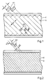
- helical tracks 1 are recorded on the magnetic tape T in a standard operation.
- Their geometric width b1 is smaller than the gap width w1 of the video heads K1.
- tracks 2 with a geometric width b2 that are half b1 compared to b1 are recorded on the magnetic tape T for a long-term operation, specifically with a second pair of video heads K2 with a gap width w2, which is also larger than the track width b2.
- the playback in standard operation that is to say in tracks 1 with the width b1
- the video heads K2 does not take place with the video heads K1 provided for this purpose, but rather with the video heads K2 per se intended for long-term operation according to FIG. 2 with the smaller gap width w2.
- w2 is larger than b2, but smaller than b1. Therefore, as shown in FIG. 1, the video heads K2 can scan the tracks 1 without detecting the neighboring tracks. The exact The position of the heads K2 in the middle of a track 1 can be adjusted by the so-called servo control of the head wheel. Because the heads K2 no longer detect the two neighboring tracks, the crosstalk is considerably reduced. This results in the advantages already described with regard to the low crosstalk attenuation, in particular for the scanned ink carrier.
- the two video heads K1 and K2 as indicated by opposite inclinations of the column, have different azimuth angles to reduce crosstalk from the neighboring tracks.
Landscapes
- Engineering & Computer Science (AREA)
- Multimedia (AREA)
- Signal Processing (AREA)
- Recording Or Reproducing By Magnetic Means (AREA)
- Television Signal Processing For Recording (AREA)
- Signal Processing Not Specific To The Method Of Recording And Reproducing (AREA)
- Electrotherapy Devices (AREA)
- Soil Working Implements (AREA)
- Diaphragms For Electromechanical Transducers (AREA)
- Two-Way Televisions, Distribution Of Moving Picture Or The Like (AREA)
- Closed-Circuit Television Systems (AREA)
Description
- Bei Videorecordern nach dem VHS-System werden mit einem rotierenden Kopfrad mit zwei Videoköpfen nacheinander Halbbilder jeweils auf Schrägspuren eines Magnetbandes aufgezeichnet. Die Aufzeichnung erfolgt dabei ohne Zwischenraum, sogenannten Rasen, zwischen den Spuren. Die Spaltbreite des Videokopfes ist größer als die Breite der auf dem Band geschriebenen Spuren. Bei der Aufzeichnung wird also jeweils ein Teil der vorher geschriebenen Spur durch die neue Spur überschrieben.
- Bei der Wiedergabe ist also die Spaltbreite des Videokopfes größer als die geometrische Breite der abgetasteten Spuren, so daß der Kopf zwangsläufig auch Signale aus den Nachbarspuren liest und somit ein Übersprechen auftritt. Für das Leuchtdichtesignal wird dieses Übersprechen im wesentlichen durch die entgegengesetzten Azimutwinkel der beiden Videoköpfe verringert. Für den Farbträger, bei dessen Frequenz die durch die unterschiedlichen Azimutwinkel hervorgerufenen Azimutverluste nicht mehr ausreichend wirksam sind, wird das Übersprechen durch sogenannte Kammfilter verringert. Die Kammfilter bewirken eine Addition der Farbträger aus zeitlich aufeinanderfolgenden Zeilen, wodurch sich die Nutzsignalkomponenten addieren und die Übersprechkomponenten einander auslöschen.
- Es sind auch Videorecorder bekannt, die zusätzlich zu einem sogenannten Standardbetrieb einen Langzeitbetrieb ermöglichen. Bei dem Langzeitbetrieb erfolgt die Aufzeichnung mit einem zweiten Paar von Videoköpfen, deren Spaltbreite etwa die Hälfte der bei Standardbetrieb ist. Außerdem ist die Längsgeschwindigkeit des Magnetbandes halbiert. Durch diese Lösung kann bei geringfügig verminderter Aufzeichnungsqualität die Spieldauer durch Halbierung der Spurbreite verdoppelt werden.
- US-A-4 633 332 zeigt einen Videorecorder mit ersten Köpfen für Standardbetrieb und zweiten Köpfen für Langzeitbetrieb. Bei DE-A-2 551 468 erfolgt die Wiedergabe mit Magnetköpfen, deren Kopfspiegel schmaler sind als die der Aufzeichnungsköpfe.
- Der Erfindung liegt die Aufgabe zugrunde, bei einem derartigen Videorecorder mit Standard- und Langzeitbetrieb das Übersprechen bei der Wiedergabe insbesondere für den Farbträger im Standardbetrieb zu vermeiden.
- Diese Aufgabe wird durch die im Anspruch 1 beschriebene Erfindung gelöst.
- Bei der erfindungsgemäßen Lösung erfolgt also bei Standardbetrieb die Wiedergabe mit den Videoköpfen, die an sich für Standardbetrieb nicht vorgesehen sind und bei der Aufzeichnung in dieser Betriebsart auch nicht verwendet wurden. Es hat sich gezeigt, daß gerade durch diese Art der Wiedergabe mehrere Vorteile insbesondere hinsichtlich des Übersprechens erzielt werden. Dabei wird die Tatsache vorteilhaft ausgenutzt, daß die Spaltbreite der Videoköpfe für Langzeitbetrieb kleiner ist als die Spurbreite bei Standardbetrieb. Die für Langzeitbetrieb vorgesehenen Videoköpfe können also die im Standardbetrieb geschriebenen breiten Spuren für die Wiedergabe so abtasten, daß die Köpfe die Nachbarspuren nicht erfassen und somit das Übersprechen vermieden wird. Das gilt insbesondere für den Farbträger, so daß bei Standardbetrieb auf das bisher verwendete Kammfilter im Weg des Farbträgers bei der Wiedergabe verzichtet werden kann. Das hat den Vorteil, daß die bei PAL-Betrieb durch das Kammfilter bewirkte Verschmelzung der Signale aus den Zeilen 1 und 3, 2 und 4 usw. und die Qualitätsverringerung beim wiederholten Überspielen reduziert werden. Es hat sich gezeigt, daß abgesehen von einer geringen Verringerung des Wiedergabepegels keine nennenswerte Verschlechterung des Störabstandes auftritt. Vielmehr wird sogar die Qualität des wiedergegebe nen Leuchtdichtesignals verbessert. Diese Verbesserungen sind unter Beibehaltung der Kompatibilität zu dem bestehenden System möglich. Bei Geräten mit DTF (Dynamic Track Following), der sogenannten dynamischen Spurnachführung, kann bei Standbildbetrieb und bei geringer Qualitätseinbuße auch bei Suchlauf auf das Kammfilter verzichtet werden, wodurch der Schaltungsaufwand verringert wird. Bei Verzicht auf die Kompatibilität zu bestehenden Systemen (VHS, Beta) kann ggf. auch die bekannte Phasenumschaltung des Farbträgers bei der Aufzeichnung entfallen.
- Die Erfindung wird anhand der Zeichnung erläutert. Darin zeigen
- Fig. 1
- das Spurmuster bei Standardbetrieb und
- Fig. 2
- das Spurmuster bei Langzeitbetrieb.
- In Fig. 1 sind bei einem Standardbetrieb auf dem Magnetband T Schrägspuren 1 aufgezeichnet. Deren geometrische Breite b1 ist geringer als die Spaltbreite w1 der Videoköpfe K1.
- In Fig. 2 sind für einen Langzeitbetrieb auf dem Magnetband T Spuren 2 mit gegenüber b1 halber geometrischer Breite b2 aufgezeichnet, und zwar mit einem zweiten Paar von Videoköpfen K2 mit einer Spaltbreite w2, die ebenfalls größer ist als die Spurbreite b2.
- Wie in Fig. 1 dargestellt, erfolgt die Wiedergabe bei Standardbetrieb, also bei Spuren 1 mit der Breite b1, nicht mit den dafür vorgesehenen Videoköpfen K1, sondern mit den an sich für Langzeitbetrieb gemäß Fig. 2 vorgesehenen Videoköpfen K2 mit der geringeren Spaltbreite w2. w2 ist zwar größer als b2, jedoch kleiner als b1. Deshalb können die Videoköpfe K2, wie Fig. 1 zeigt, jeweils die Spuren 1 abtasten, ohne dabei die Nachbarspuren zu erfassen. Die genaue Lage der Köpfe K2 in der Mitte einer Spur 1 kann durch die sogenannte Servoregelung des Kopfrades eingestellt werden. Dadurch, daß die Köpfe K2 die beiden Nachbarspuren nicht mehr erfassen, wird das Übersprechen beträchtlich verringert. Dadurch ergeben sich die bereits beschriebenen Vorteile hinsichtlich der geringen Übersprechdämpfung insbesondere für den abgetasteten Farbträger.
- Die beiden Videoköpfe K1 und ebenso K2 haben wie angedeutet durch entgegengesetzte Neigungen der Spalte unterschiedliche Azimutwinkel zur Verringerung des Übersprechens aus den Nachbarspuren. In der Praxis gelten für die in Fig. 1 und 2 dargestellten Teile z.B. folgende Werte:
b1 = 49 µm
b2 = 24,5 µm
w1 = 60 - 80 µm
w2 = 35 µm.
Claims (1)
- Videorecorder mit Standard- und Langzeitbetrieb, bei dem die Spuren (1, 2) bei Standardbetrieb mit ersten Videoköpfen (K1) einer ersten Spaltbreite (wl) bei einer ersten Bandlängsgeschwindigkeit und bei Langzeitbetrieb mit zweiten Videoköpfen (K2) mit einer zweiten, geringeren Spaltbreite (w2) bei einer zweiten, geringeren Bandlängsgeschwindigkeit geschrieben und gelesen werden, dadurch gekennzeichnet, daß die Wiedergabe bei Standardbetrieb (Fig. 1) mit den zweiten Videoköpfen (K2) und bei Standardbetrieb (Fig. 1) während Sonderbetriebsarten wie Standbild, Suchlauf u. dgl. mit den ersten Videoköpfen (K1) erfolgt.
Applications Claiming Priority (2)
| Application Number | Priority Date | Filing Date | Title |
|---|---|---|---|
| DE3711951 | 1987-04-09 | ||
| DE19873711951 DE3711951A1 (de) | 1987-04-09 | 1987-04-09 | Videorecorder mit standard- und langzeitbetrieb |
Publications (3)
| Publication Number | Publication Date |
|---|---|
| EP0286045A2 EP0286045A2 (de) | 1988-10-12 |
| EP0286045A3 EP0286045A3 (de) | 1991-05-22 |
| EP0286045B1 true EP0286045B1 (de) | 1994-12-28 |
Family
ID=6325198
Family Applications (1)
| Application Number | Title | Priority Date | Filing Date |
|---|---|---|---|
| EP88105359A Expired - Lifetime EP0286045B1 (de) | 1987-04-09 | 1988-04-02 | Videorecorder mit Standard- und Langzeitbetrieb |
Country Status (7)
| Country | Link |
|---|---|
| EP (1) | EP0286045B1 (de) |
| JP (1) | JP2888836B2 (de) |
| KR (1) | KR0123533B1 (de) |
| AT (1) | ATE116502T1 (de) |
| DE (2) | DE3711951A1 (de) |
| ES (1) | ES2065896T3 (de) |
| HK (1) | HK50796A (de) |
Families Citing this family (5)
| Publication number | Priority date | Publication date | Assignee | Title |
|---|---|---|---|---|
| EP0337590A3 (de) * | 1988-04-13 | 1990-01-17 | Liberty Pool Products S.A. | Schwimmbadreiniger |
| DE3920591A1 (de) * | 1989-06-23 | 1991-01-03 | Thomson Brandt Gmbh | Videorecorder mit ueberspiel-moeglichkeit |
| JP3161712B2 (ja) * | 1989-07-12 | 2001-04-25 | 株式会社日立製作所 | 磁気記録再生装置 |
| US5183722A (en) | 1989-12-01 | 1993-02-02 | Tosoh Corporation | Positive photosensitive composition for forming lenses containing 1,2-naphthoquinone diazide sulfonate photosensitizer, alkali-soluble resin and thermosetting agent and process for producing the composition |
| KR100550447B1 (ko) * | 2004-11-19 | 2006-02-08 | 씨제이 주식회사 | 혼합나물의 제조 방법 |
Family Cites Families (6)
| Publication number | Priority date | Publication date | Assignee | Title |
|---|---|---|---|---|
| DE1150707B (de) * | 1960-10-12 | 1963-06-27 | Victor Company Of Japan | Verfahren zur magnetischen Aufzeichnung und Wiedergabe von Signalen hoher Frequenz, insbesondere von Fernsehsignalen |
| DE2551468A1 (de) * | 1975-11-15 | 1977-05-18 | Bosch Gmbh Robert | Magnetbandgeraet |
| JPS629532Y2 (de) * | 1978-10-16 | 1987-03-05 | ||
| JPS5694505A (en) * | 1979-12-27 | 1981-07-31 | Hitachi Denshi Ltd | Magnetic recording and reproducing system |
| JPS57130205A (en) * | 1981-02-03 | 1982-08-12 | Hitachi Ltd | Magnetic recording and reproducing device |
| JPS59127202A (ja) * | 1983-01-11 | 1984-07-23 | Victor Co Of Japan Ltd | 多重磁気記録装置及び多重磁気記録再生装置 |
-
1987
- 1987-04-09 DE DE19873711951 patent/DE3711951A1/de not_active Withdrawn
-
1988
- 1988-03-29 JP JP63073504A patent/JP2888836B2/ja not_active Expired - Fee Related
- 1988-04-02 EP EP88105359A patent/EP0286045B1/de not_active Expired - Lifetime
- 1988-04-02 AT AT88105359T patent/ATE116502T1/de not_active IP Right Cessation
- 1988-04-02 ES ES88105359T patent/ES2065896T3/es not_active Expired - Lifetime
- 1988-04-02 DE DE3852557T patent/DE3852557D1/de not_active Expired - Fee Related
- 1988-04-08 KR KR1019880003961A patent/KR0123533B1/ko not_active Expired - Fee Related
-
1996
- 1996-03-21 HK HK50796A patent/HK50796A/xx not_active IP Right Cessation
Also Published As
| Publication number | Publication date |
|---|---|
| KR0123533B1 (ko) | 1997-11-28 |
| ES2065896T3 (es) | 1995-03-01 |
| EP0286045A2 (de) | 1988-10-12 |
| JPS641103A (en) | 1989-01-05 |
| KR880013141A (ko) | 1988-11-30 |
| DE3711951A1 (de) | 1988-11-10 |
| EP0286045A3 (de) | 1991-05-22 |
| JP2888836B2 (ja) | 1999-05-10 |
| DE3852557D1 (de) | 1995-02-09 |
| ATE116502T1 (de) | 1995-01-15 |
| HK50796A (en) | 1996-03-29 |
Similar Documents
| Publication | Publication Date | Title |
|---|---|---|
| EP0264375B1 (de) | Verfahren und einrichtung zur elektronischen bearbeitung von gespeicherten videosignalen | |
| DE69420551T2 (de) | Verfahren zum Aufzeichnen/Wiedergeben von digitalen Videosignalen auf Band | |
| EP0061050B1 (de) | Videorecorder zur Aufzeichnung eines mit dem Videosignal frequenzmodulierten Bildträgers | |
| DE3231248A1 (de) | Nachlaufservosystem fuer magnetische, flexible magnetplatten verwendende aufzeichnungs- und wiedergabegeraete | |
| DE68925915T2 (de) | Magnetisches Aufzeichnungs- und Wiedergabegerät | |
| EP0286045B1 (de) | Videorecorder mit Standard- und Langzeitbetrieb | |
| DE3339639A1 (de) | Farbvideosignal-aufzeichnungseinrichtung und farbvideosignal-aufzeichnungs- und -wiedergabeanordnung | |
| DE69228726T2 (de) | Digitaler Videobandrecorder | |
| DE3520537A1 (de) | Digital-videomagnetbandrecorder | |
| DE2641816C3 (de) | Anordnung zur Aufzeichnung und/oder Wiedergabe breitbandiger Videosignale | |
| EP0226796B1 (de) | Videorecorder für Fernsehen erhöhter Auflösung | |
| DE3322986C2 (de) | Videorecorder mit Aufzeichnung eines oder mehrerer Tonsignale | |
| DE3510766C2 (de) | ||
| DE19648172B4 (de) | Magnetische Aufzeichnungs- und Wiedergabevorrichtung | |
| DE3146774C2 (de) | Wiedergabegerät für ein Videoband | |
| EP0284768B1 (de) | Kammfilter für Videorecorder | |
| DE3739404C2 (de) | Überwachungs-Videorekorder | |
| DE3851820T2 (de) | Wiedergabeverfahren für Bandrekorder mit Drehkopf. | |
| DE3737054C3 (de) | Videosignalaufzeichnungs-/ -wiedergabegerät | |
| DE3850173T2 (de) | Vorrichtung zur magnetischen Aufzeichnung eines Videosignals und eines Audiosignals. | |
| DE3925628C2 (de) | Magnetbandgerät, insbesondere Videorecorder, mit einer Einrichtung zur HiFi-Stereo-Nachvertonung | |
| DE3807630C1 (de) | ||
| DE4021942A1 (de) | Videorecorder | |
| DE3409187A1 (de) | Verfahren zum aufzeichnen und/oder wiedergeben von breitbandigen signalen | |
| DE69127863T2 (de) | Aufzeichnungs-/Wiedergabegerät für Video- und Audiosignale |
Legal Events
| Date | Code | Title | Description |
|---|---|---|---|
| PUAI | Public reference made under article 153(3) epc to a published international application that has entered the european phase |
Free format text: ORIGINAL CODE: 0009012 |
|
| AK | Designated contracting states |
Kind code of ref document: A2 Designated state(s): AT BE CH DE ES FR GB GR IT LI LU NL SE |
|
| 17P | Request for examination filed |
Effective date: 19901231 |
|
| PUAL | Search report despatched |
Free format text: ORIGINAL CODE: 0009013 |
|
| AK | Designated contracting states |
Kind code of ref document: A3 Designated state(s): AT BE CH DE ES FR GB GR IT LI LU NL SE |
|
| 17Q | First examination report despatched |
Effective date: 19930510 |
|
| GRAA | (expected) grant |
Free format text: ORIGINAL CODE: 0009210 |
|
| AK | Designated contracting states |
Kind code of ref document: B1 Designated state(s): AT BE CH DE ES FR GB GR IT LI LU NL SE |
|
| PG25 | Lapsed in a contracting state [announced via postgrant information from national office to epo] |
Ref country code: NL Effective date: 19941228 Ref country code: GR Free format text: LAPSE BECAUSE OF FAILURE TO SUBMIT A TRANSLATION OF THE DESCRIPTION OR TO PAY THE FEE WITHIN THE PRESCRIBED TIME-LIMIT Effective date: 19941228 Ref country code: BE Effective date: 19941228 |
|
| REF | Corresponds to: |
Ref document number: 116502 Country of ref document: AT Date of ref document: 19950115 Kind code of ref document: T |
|
| ITF | It: translation for a ep patent filed | ||
| REF | Corresponds to: |
Ref document number: 3852557 Country of ref document: DE Date of ref document: 19950209 |
|
| GBT | Gb: translation of ep patent filed (gb section 77(6)(a)/1977) |
Effective date: 19950116 |
|
| REG | Reference to a national code |
Ref country code: ES Ref legal event code: FG2A Ref document number: 2065896 Country of ref document: ES Kind code of ref document: T3 |
|
| ET | Fr: translation filed | ||
| PG25 | Lapsed in a contracting state [announced via postgrant information from national office to epo] |
Ref country code: SE Effective date: 19950328 |
|
| PG25 | Lapsed in a contracting state [announced via postgrant information from national office to epo] |
Ref country code: AT Effective date: 19950402 |
|
| PG25 | Lapsed in a contracting state [announced via postgrant information from national office to epo] |
Ref country code: LU Free format text: LAPSE BECAUSE OF NON-PAYMENT OF DUE FEES Effective date: 19950430 Ref country code: LI Effective date: 19950430 Ref country code: CH Effective date: 19950430 |
|
| NLV1 | Nl: lapsed or annulled due to failure to fulfill the requirements of art. 29p and 29m of the patents act | ||
| PLBE | No opposition filed within time limit |
Free format text: ORIGINAL CODE: 0009261 |
|
| STAA | Information on the status of an ep patent application or granted ep patent |
Free format text: STATUS: NO OPPOSITION FILED WITHIN TIME LIMIT |
|
| REG | Reference to a national code |
Ref country code: CH Ref legal event code: PL |
|
| 26N | No opposition filed | ||
| REG | Reference to a national code |
Ref country code: GB Ref legal event code: 746 Effective date: 19970909 |
|
| REG | Reference to a national code |
Ref country code: FR Ref legal event code: D6 |
|
| REG | Reference to a national code |
Ref country code: GB Ref legal event code: IF02 |
|
| PGFP | Annual fee paid to national office [announced via postgrant information from national office to epo] |
Ref country code: GB Payment date: 20020307 Year of fee payment: 15 |
|
| PGFP | Annual fee paid to national office [announced via postgrant information from national office to epo] |
Ref country code: FR Payment date: 20020417 Year of fee payment: 15 |
|
| PGFP | Annual fee paid to national office [announced via postgrant information from national office to epo] |
Ref country code: ES Payment date: 20020424 Year of fee payment: 15 |
|
| PGFP | Annual fee paid to national office [announced via postgrant information from national office to epo] |
Ref country code: DE Payment date: 20020516 Year of fee payment: 15 |
|
| PG25 | Lapsed in a contracting state [announced via postgrant information from national office to epo] |
Ref country code: GB Free format text: LAPSE BECAUSE OF NON-PAYMENT OF DUE FEES Effective date: 20030402 |
|
| PG25 | Lapsed in a contracting state [announced via postgrant information from national office to epo] |
Ref country code: ES Free format text: LAPSE BECAUSE OF NON-PAYMENT OF DUE FEES Effective date: 20030403 |
|
| PG25 | Lapsed in a contracting state [announced via postgrant information from national office to epo] |
Ref country code: DE Free format text: LAPSE BECAUSE OF NON-PAYMENT OF DUE FEES Effective date: 20031101 |
|
| GBPC | Gb: european patent ceased through non-payment of renewal fee |
Effective date: 20030402 |
|
| PG25 | Lapsed in a contracting state [announced via postgrant information from national office to epo] |
Ref country code: FR Free format text: LAPSE BECAUSE OF NON-PAYMENT OF DUE FEES Effective date: 20031231 |
|
| REG | Reference to a national code |
Ref country code: FR Ref legal event code: ST |
|
| REG | Reference to a national code |
Ref country code: ES Ref legal event code: FD2A Effective date: 20030403 |
|
| PG25 | Lapsed in a contracting state [announced via postgrant information from national office to epo] |
Ref country code: IT Free format text: LAPSE BECAUSE OF NON-PAYMENT OF DUE FEES;WARNING: LAPSES OF ITALIAN PATENTS WITH EFFECTIVE DATE BEFORE 2007 MAY HAVE OCCURRED AT ANY TIME BEFORE 2007. THE CORRECT EFFECTIVE DATE MAY BE DIFFERENT FROM THE ONE RECORDED. Effective date: 20050402 |