EP0285754A2 - Begrenzungsanschlag für den Schwenkwinkel eines um eine Lagerachse beweglichen Armes - Google Patents
Begrenzungsanschlag für den Schwenkwinkel eines um eine Lagerachse beweglichen Armes Download PDFInfo
- Publication number
- EP0285754A2 EP0285754A2 EP88101354A EP88101354A EP0285754A2 EP 0285754 A2 EP0285754 A2 EP 0285754A2 EP 88101354 A EP88101354 A EP 88101354A EP 88101354 A EP88101354 A EP 88101354A EP 0285754 A2 EP0285754 A2 EP 0285754A2
- Authority
- EP
- European Patent Office
- Prior art keywords
- stop
- tabs
- strut
- arm
- longitudinal slot
- Prior art date
- Legal status (The legal status is an assumption and is not a legal conclusion. Google has not performed a legal analysis and makes no representation as to the accuracy of the status listed.)
- Granted
Links
Images
Classifications
-
- E—FIXED CONSTRUCTIONS
- E05—LOCKS; KEYS; WINDOW OR DOOR FITTINGS; SAFES
- E05C—BOLTS OR FASTENING DEVICES FOR WINGS, SPECIALLY FOR DOORS OR WINDOWS
- E05C17/00—Devices for holding wings open; Devices for limiting opening of wings or for holding wings open by a movable member extending between frame and wing; Braking devices, stops or buffers, combined therewith
- E05C17/02—Devices for holding wings open; Devices for limiting opening of wings or for holding wings open by a movable member extending between frame and wing; Braking devices, stops or buffers, combined therewith by mechanical means
- E05C17/04—Devices for holding wings open; Devices for limiting opening of wings or for holding wings open by a movable member extending between frame and wing; Braking devices, stops or buffers, combined therewith by mechanical means with a movable bar or equivalent member extending between frame and wing
- E05C17/30—Devices for holding wings open; Devices for limiting opening of wings or for holding wings open by a movable member extending between frame and wing; Braking devices, stops or buffers, combined therewith by mechanical means with a movable bar or equivalent member extending between frame and wing of extensible, e.g. telescopic, construction
-
- Y—GENERAL TAGGING OF NEW TECHNOLOGICAL DEVELOPMENTS; GENERAL TAGGING OF CROSS-SECTIONAL TECHNOLOGIES SPANNING OVER SEVERAL SECTIONS OF THE IPC; TECHNICAL SUBJECTS COVERED BY FORMER USPC CROSS-REFERENCE ART COLLECTIONS [XRACs] AND DIGESTS
- Y10—TECHNICAL SUBJECTS COVERED BY FORMER USPC
- Y10T—TECHNICAL SUBJECTS COVERED BY FORMER US CLASSIFICATION
- Y10T403/00—Joints and connections
- Y10T403/32—Articulated members
- Y10T403/32008—Plural distinct articulation axes
-
- Y—GENERAL TAGGING OF NEW TECHNOLOGICAL DEVELOPMENTS; GENERAL TAGGING OF CROSS-SECTIONAL TECHNOLOGIES SPANNING OVER SEVERAL SECTIONS OF THE IPC; TECHNICAL SUBJECTS COVERED BY FORMER USPC CROSS-REFERENCE ART COLLECTIONS [XRACs] AND DIGESTS
- Y10—TECHNICAL SUBJECTS COVERED BY FORMER USPC
- Y10T—TECHNICAL SUBJECTS COVERED BY FORMER US CLASSIFICATION
- Y10T74/00—Machine element or mechanism
- Y10T74/20—Control lever and linkage systems
- Y10T74/20576—Elements
- Y10T74/20582—Levers
- Y10T74/2063—Stops
Definitions
- the invention relates to a limit stop for the pivot angle of an arm movable about a bearing axis, in which a strut is articulated on the one hand on the component supporting the bearing axis and on the other hand engages the arm at a distance from the bearing axis.
- limit stops are often required, for example, in the development area of building hardware. For example, they are used to limit the opening angle of opening arms for windows and doors relative to the fixed frame and / or the sash.
- a generic limit stop which has a simple construction with a relatively small installation space and high functional reliability.
- Such a limit stop is characterized by the characterizing features of claim 1, namely characterized in that the strut consists of two structurally identical tabs, each with a longitudinal slot and a stop tongue in front of it and angled from the tab plane, in that the stop tongue of each tab is only pushed longitudinally into the longitudinal slot of the other tab, so that the stop end of the Longitudinal slot of each tab whose stop tongue is adjacent, that each stop tongue has sideways projecting support lugs, which can only be brought into support engagement with the longitudinal edges of the longitudinal slot in the tabs in the region of an enlarged end notch from the stop end of the longitudinal slot, and that the relative displacement of the Tabs can be limited to a dimension that is less than the distance between the stop end and the extended end notch of the longitudinal slots of both tabs.
- the mutually facing ends of the two tabs can only be pivoted on the one hand to the bearing-bearing component and on the other hand to the arm, while claim 3 provides that the tabs of the strut consist of strip material with a flat rectangular cross-section.
- the tabs for forming a limit stop according to the invention can be easily and simply manufactured as stamped and bent parts, and that two of these tabs can be put together by simple plug-in coupling connections to form a strut which serves as a limit stop and can be adjusted within predetermined limits.
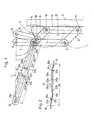
- Fig. 1 of the drawing is shown in a schematically simplified representation, namely by a dash-dotted line, the fixed frame 1 of a window, a door or the like, on which a wing 3 is pivotally suspended via a support and guide link system 2.
- the support and guide link system 2 has a support arm 4 which is suspended on the fixed frame 1 so as to be pivotable about a bearing axis 5. With the support arm 4 two links 8 and 9 are connected via two pivot pins 6 and 7, which have a matching length dimension. Each of the links 8 and 9 is in turn connected via a respective pivot pin 10 or 11 to a guide rail 12 which can be fixed on the wing 3, lying parallel to its plane.
- the section of the support arm 4 located between the pivot pins 6 and 7 forms, with the two links 8 and 9 and with the guide rail 12 carrying the two pivot pins 10 and 11, a link parallelogram 13 which connects the wing 3 to the fixed frame 1.
- the movement of the handlebar parallelogram 13 is influenced by a control link 14 which is pivotally suspended on the one hand on the fixed frame about a pivot pin 15 and on the other hand engages with a pivot pin 16 between the pivot pins 6 and 10 on the handlebar 8.
- the control arm 14 acts on the parallelogram 13 so that the wing 3 is guided in its opening and closing movement along a path which is at least approximately delimited by a circular arc around a latent hinge axis which is in the vicinity of the bearing points 5 and 15 adjacent side edge of the wing 3 is.
- a strut 17 is therefore used as a limit stop for the pivoting angle of the support arm 4, which is pivotally suspended on the one hand and the articulation pin 18 on the fixed frame 1 and on the other hand acts on the support arm 4, for example via the articulation pin 6, at a distance from the bearing axis 5.
- the strut 17 is formed by two identical tabs 19a and 19b. Each of these tabs 19a and 19b has a longitudinal slot 20a or 20b and is also provided with a stop tongue 21a or 21b angled out of the tab plane.
- each bracket 19a or 19b engages in the longitudinal slot 20b or 20a of the other bracket 19b or 19a only in a longitudinally displaceable manner.
- the stop end 22b or 22a of the longitudinal slot 20b or 20a of each tab 19b or 19a is provided adjacent to its stop tongue 21b or 21a.
- the distance between the articulation axes 6 and 18 thereof is limited to the dimension 23.
- the stop tongue 21a of the bracket 20a then interacts with the stop end 22b in the longitudinal slot 20b of the bracket 19b, while conversely the stop tongue 21b of the bracket 19b comes into contact with the stop end 22a in the longitudinal slot 20a of the bracket 19a, as is the case 1 can be clearly seen.
- each stop tongue 21a and 21b has, at its free end, laterally projecting support lugs 24a and 24b.
- These support lugs 24a and 24b can only in the region of an enlarged end notch 25a or 25b, the end of the longitudinal slot 20a remote from the stop end 22a or 22b or 20b is assigned to be brought into support and holding engagement with the longitudinal edges of the longitudinal slots 20a or 20b.
- the relative displacement of the tabs 19a and 19b to one another is then limited to a dimension 26 which is the distance between the stop end 22a or 22b and the extended end notch 25a or 25b of the longitudinal slots 20a and 20b falls below both tabs 19a and 19b.
- An undesired and automatic decoupling of the two straps 17a and 19b forming the strut 17 is thereby counteracted in a simple manner.
- the two tabs 19a and 19b of the strut 17 are structurally completely identical and can therefore be manufactured as stamped and bent parts in one and the same tool, preferably from strip material with a flat rectangular cross section. It is important that the stop tongues 21a and 21b of the two tabs 19a and 19b only engage in the longitudinal slots 20b and 20a assigned to them in a longitudinally displaceable manner, while the free ends of the strut 17 are only pivotably held on the pivot pins 6 and 18.
- the use of the strut 17 as a limit stop for the swivel angle of an arm movable about a bearing axis is not limited to support and guide link systems 2, as shown in FIG. 1. Rather, a limit stop formed by the strut 17 can be used wherever the aim is to limit the swivel angle for an arm movable about a bearing axis relative to the component carrying the bearing axis.
Landscapes
- Mechanical Engineering (AREA)
- Engineering & Computer Science (AREA)
- Forklifts And Lifting Vehicles (AREA)
- Vehicle Body Suspensions (AREA)
- Peptides Or Proteins (AREA)
- Control Of Vending Devices And Auxiliary Devices For Vending Devices (AREA)
- Wing Frames And Configurations (AREA)
- Mechanical Control Devices (AREA)
- Transmission Devices (AREA)
- Manipulator (AREA)
- Spinning Or Twisting Of Yarns (AREA)
- Hinges (AREA)
- Braking Arrangements (AREA)
- Chair Legs, Seat Parts, And Backrests (AREA)
- Support Devices For Sliding Doors (AREA)
- Agricultural Machines (AREA)
- Steering-Linkage Mechanisms And Four-Wheel Steering (AREA)
- Pivots And Pivotal Connections (AREA)
Abstract
Description
- Die Erfindung betrifft einen Begrenzungsanschlag für den Schwenkwinkel eines um eine Lagerachse beweglichen Armes, bei welchem eine Strebe einerseits an dem die Lagerachse tragenden Bauteil angelenkt ist und andererseits am Arm im Abstand von der Lagerachse angreift.
- Derartige Begrenzungsanschläge werden beispielsweise auf dem Entwicklungsgebiet der Baubeschläge oft benötigt. So werden sie beispielsweise benutzt, um den Öffnungswinkel von Ausstellarmen für Fenster und Türen relativ zum feststehenden Rahmen und/oder zum Flügel zu begrenzen.
- Der für die Unterbringung solcher Begrenzungsanschläge verfügbare Einbauraum ist dabei oft relativ gering. Trotzdem ist es aber wichtig, daß die Begrenzungsanschläge die ihnen zugedachte Funktion dauerhaft sicher erfüllen.
- Nach der Erfindung wird ein gattungsgemäßer Begrenzungsanschlag geschaffen, der bei relativ geringem Einbauraum und hoher Funktionssicherheit eine bauliche einfache Ausgestaltung aufweist. Ein solcher Begrenzungsanschlag zeichnet sich durch die Kennzeichnungsmerkmale des Anspruchs 1, nämlich dadurch, aus, daß die Strebe aus zwei baugleichen Laschen mit je einem Längsschlitz und einer diesem mit Abstand vorgelagerten sowie aus der Laschenebene abgewinkelten Anschlagzunge besteht, daß die Anschlagzunge jeder Lasche jeweils in den Längsschlitz der anderen Lasche ausschließlich längsschiebbar eingerückt ist, daß das Anschlagende des Längsschlitzes jeder Lasche deren Anschlagzunge benachbart liegt, daß jede Anschlagzunge an ihrem Ende seitwärts auskragende Stütznasen aufweist, die lediglich im Bereich einer erweiterten, vom Anschlagende des Längsschlitzes entfernten Endausklinkung mit den Längskanten des Längsschlitzes in den Laschen in Stützeingriff bringbar ist, und daß die Relativverschiebung der Laschen auf ein Maß begrenzbar ist, das den Abstand zwischen dem Anschlagende und der erweiterten Endausklinkung der Längsschlitze beider Laschen unterschreitet.
- Nach Anspruch 2 können erfindungsgemäß die voneinander abgewendeten Enden beider Laschen lediglich schwenkbar einerseits an dem die Lagerachse tragenden Bauteil und andererseits am Arm angelenkt sein, während Anspruch 3 vorsieht, daß die Laschen der Strebe aus Bandmaterial mit flachrechteckigem Querschnitt bestehen.
- Es liegt auf der Hand, daß die Laschen zur Bildung eines erfindungsgemäßen Begrenzungsanschlags leicht und einfach als Stanzbiegeteile gefertigt werden können und daß sich dabei jeweils zwei dieser Laschen durch einfache Steckkupplungsverbindungen zu einer als Begrenzungsanschlag dienenden, innerhalb vorgegebener Grenzen längerverstellbaren Strebe zusammensetzen lassen.
- In der Zeichnung ist der Gegenstand der Erfindung in einem Ausführungsbeispiel dargestellt. Es zeigt
- Fig. 1 eine Draufsicht auf einen Begrenzungsanschlag in Wirkverbindung mit einem Trag- und Führungslenkersystem für den Flügel eines Fensters, einer Tür od. dgl. bei Wirkstellung des Begrenzungsanschlags und
- Fig. 2 einen Längsschnitt durch den Begrenzungsanschlag nach Fig. 1 in Ruhestellung bzw. zusammengeschobenem Zustand.
- In Fig. 1 der Zeichnung ist in schematisch vereinfachter Darstellung, nämlich durch eine strichpunktierte Linie, der feststehende Rahmen 1 eines Fensters, einer Tür od. dgl. gezeigt, an dem über ein Trag- und Führungslenkersystem 2 ein Flügel 3 schwenkbeweglich aufgehängt ist.
- Das Trag- und Führungslenkersystem 2 weist dabei einen Tragarm 4 auf, der um eine Lagerachse 5 schwenkbeweglich am feststehenden Rahmen 1 aufgehängt ist. Mit dem Tragarm 4 sind über zwei Gelenkzapfen 6 und 7 zwei Lenker 8 und 9 verbunden, die eine übereinstimmende Längenabmessung haben. Jeder der Lenker 8 und 9 ist dabei wiederum über je einen Gelenkzapfen 10 bzw. 11 an eine Führungsschiene 12 angeschlossen, die am Flügel 3, parallel zu dessen Ebene liegende, festgelegt werden kann. Der zwischen den Gelenkzapfen 6 und 7 gelegene Teilabschnitt des Tragarms 4 bildet mit den beiden Lenkern 8 und 9 sowie mit der die beiden Gelenkzapfen 10 und 11 tragenden Führungsschiene 12 ein Lenkerparallelogramm 13, welches den Flügel 3 mit dem feststehenden Rahmen 1 verbindet. Die Bewegung des Lenkerparallelogramms 13 wird dabei durch einen Steuerlenker 14 beeinflußt, der einerseits um einen Gelenkzapfen 15 schwenkbar am feststehenden Rahmen aufgehängt ist und andererseits mit einem Gelenkzapfen 16 zwischen den Gelenkzapfen 6 und 10 am Lenker 8 angreift. Der Steuerlenker 14 wirkt dabei auf das Lenkerparallelogramm 13 so ein, daß der Flügel 3 bei seiner Öffnungs- und Schließbewegung längs einer Bahn geführt wird, die wenigstens annähernd von Kreisbogen um eine latente Gelenkachse begrenzt ist, die in der Nähe der den Lagerstellen 5 und 15 benachbarten Seitenkante des Flügels 3 liegt.
- Damit Beschädigungen am Fenster oder an der Tür sowie an den Trag- und Führungslenkersystemen 2 vermieden werden, ist es notwendig, den Schwenk winkel für den Tragarm 4 um seine Lagerachse 5, beispielsweise auf 90° zur Ebene des feststehenden Rahmens 1, zu begrenzen. Als Begrenzungsanschlag für den Schwenkwinkel des Tragarmes 4 wird daher eine Strebe 17 benutzt, die einerseits und den Gelenkzapfen 18 am feststehenden Rahmen 1 schwenkbeweglich aufgehängt ist und andererseits am Tragarm 4, beispielsweise über den Gelenkzapfen 6, im Abstand von der Lagerachse 5 angreift.
- Die Strebe 17 wird dabei von zwei baugleichen Laschen 19a und 19b gebildet. Jede dieser Laschen 19a und 19b weist einen Längsschlitz 20a bzw. 20b auf und ist darüberhinaus mit einer aus der Laschenebene abgewinkelten Anschlagzunge 21a bzw. 21b versehen.
- Die Anschlagzunge 21a bzw. 21b jeder Lasche 19a bzw. 19b greift jeweils in den Längsschlitz 20b bzw. 20a der anderen Lasche 19b bzw. 19a ausschließlich längsverschiebbar ein. Dabei ist das Anschlagende 22b bzw. 22a des Längsschlitzes 20b bzw. 20a jeder Lasche 19b bzw. 19a benachbart von deren Anschlagzunge 21b bzw. 21a vorgesehen.
- In der aus Fig. 1 ersichtlichen, ausgezogenen Endstellung der Strebe 17 wird der Abstand zwischen deren Anlenkachsen 6 und 18 auf das Maß 23 begrenzt. Bei dieser ausgezogenen Länge der Strebe 17 wirkt dann die Anschlagzunge 21a der Lasche 20a mit dem Anschlagende 22b im Längsschlitz 20b der Lasche 19b zusammen, während umgekehrt die Anschlagzunge 21b der Lasche 19b am Anschlagende 22a im Längsschlitz 20a der Lasche 19a zur Anlage kommt, wie das deutlich der Fig. 1 entnommen werden kann.
- Damit die die Strebe 17 bildenden Laschen 19a und 19b auf einfache Art und Weise zusammengebaut und zusammengehalten werden können, weist jede Anschlagzunge 21a und 21b an ihrem freien Ende seitwärts auskragende Stütznasen 24a bzw. 24b auf. Diese Stütznasen 24a bzw. 24b können lediglich im Bereich einer erweiterten Endausklinkung 25a bzw. 25b, die dem vom Anschlagende 22a bzw. 22b entfernten Ende des Längsschlitzes 20a bzw. 20b zugeordnet ist, mit den Längskanten der Längsschlitze 20a bzw. 20b in Stütz- und Halteeingriff gebracht werden.
- Nach dem Zusammensetzen der beiden Laschen 19a und 19b zur Strebe 17 wird dann die Relativverschiebung der Laschen 19a und 19b zueinander auf ein Maß 26 begrenzt, das den Abstand zwischen dem Anschlagende 22a bzw. 22b und der erweiterten Endausklinkung 25a bzw. 25b der Längsschlitze 20a und 20b beider Laschen 19a und 19b unterschreitet. Einem unerwünschten und selbsttätigen Entkuppeln der die Strebe 17 bildenden beiden Laschen 19a und 19b wird dadurch auf einfache Art und Weise entgegengewirkt.
- Die beiden Laschen 19a und 19b der Strebe 17 sind baulich völlig identisch gestaltet und können daher in ein und demselben Werkzeug, vorzugsweise aus Bandmaterial mit flach-rechteckigem Querschnitt, als Stanzbiegeteile gefertigt werden. Wichtig ist dabei, daß die Anschlagzungen 21a und 21b der beiden Laschen 19a und 19b in die ihnen zugeordneten Längsschlitze 20b und 20a lediglich längsverschiebbar eingreifen, während die freien Enden der Strebe 17 auf den Gelenkzapfen 6 und 18 lediglich schwenkbeweglich gehalten sind.
- Selbstverständlich ist die Benutzung der Strebe 17 als Begrenzungsanschlag für den Schwenkwinkel eines um eine Lagerachse beweglichen Armens nicht auf Trag- und Führungslenkersysteme 2 beschränkt, wie sie in Fig. 1 gezeigt sind. Vielmehr ist ein durch die Strebe 17 gebildeter Begrenzungsanschlag überall dort benutzbar, wo es darum geht, den Schwenkwinkel für einen um eine Lagerachse beweglichen Arm relativ zu dem die Lagerachse tragenden Bauteil zu begrenzen.
- Abschließend sie noch erwähnt, daß es nach dem Zusammenbau der Laschen 19a und 19b zur Strebe 17 auch möglich ist, in die Endausklinkungen 25a und 25b der Längsschlitze 20a und 20b Füllstücke, z.B. aus Kunststoff, rastend einzudrücken, um dadurch das unerwünschte Entkuppeln zu verhindern.
Claims (3)
dadurch gekennzeichnet,
daß die Strebe (17) aus zwei baugleichen Laschen (19a, 19b) mit je einem Längsschlitz (20a, 20b) und einer diesem mit Abstand vorgelagerten sowie aus der Laschenebene abgewinkelten Anschlagzunge (21a, 21b) besteht,
daß die Anschlagzunge (21a, 21b) jeder Lasche (19a, 19b) jeweils in den Längsschlitz (20b bzw. 20a) der anderen Lasche (19b bzw. 19a) ausschließlich längsschiebbar eingerückt ist,
daß das Anschlagende (22b bzw. 22a) des Längsschlitzes (20b bzw. 20a) jeder Lasche (19b bzw. 19a) deren Anschlagzunge (21b bzw. 21a) benachbart liegt,
daß jede Anschlagzunge (21a, 21b) an ihrem Ende seitwärts auskragende Stütznasen (24a, 24b) aufweist, die lediglich im Bereich einer erweiterten, vom Anschlagende (22a, 22b) des Längsschlitzes (20a, 20b) entfernten Endausklinkung (25a, 25b) mit den Langskanten der Längsschlitze (20a, 20b) in den Laschen (19a, 19b) in Stützeingriff bringbar sind,
und daß die Relativverschiebung der Laschen (19a und 19b) auf ein Maß (26) begrenzbar ist, das den Abstand zwischen dem Anschlagende (22a bzw. 22b) und der erweiterten Endausklinkung (25a bzw. 25b) der Längsschlitze (20a bzw. 20b) beider Laschen (19a bzw. 19b) unterschreitet (Fig. 2).
dadurch gekennzeichnet,
daß die voneinander abgewendeten Enden beider Laschen (19a und 19b) lediglich schwenkbar einerseits an dem die Lagerachse (5) tragenden Bauteil (1) und andererseits am Arm (4) angelenkt sind (18 und 6).
dadurch gekennzeichnet,
daß die Laschen (19a und 19b) der Strebe (17) - als Stanz-Biegetile - aus Bandmaterial mit flach-rechteckigem Querschnitt gefertigt sind.
Priority Applications (1)
| Application Number | Priority Date | Filing Date | Title |
|---|---|---|---|
| AT88101354T ATE53429T1 (de) | 1987-04-04 | 1988-01-30 | Begrenzungsanschlag fuer den schwenkwinkel eines um eine lagerachse beweglichen armes. |
Applications Claiming Priority (2)
| Application Number | Priority Date | Filing Date | Title |
|---|---|---|---|
| DE8705069U | 1987-04-04 | ||
| DE8705069U DE8705069U1 (de) | 1987-04-04 | 1987-04-04 |
Publications (3)
| Publication Number | Publication Date |
|---|---|
| EP0285754A2 true EP0285754A2 (de) | 1988-10-12 |
| EP0285754A3 EP0285754A3 (en) | 1988-11-09 |
| EP0285754B1 EP0285754B1 (de) | 1990-06-06 |
Family
ID=6806739
Family Applications (1)
| Application Number | Title | Priority Date | Filing Date |
|---|---|---|---|
| EP88101354A Expired - Lifetime EP0285754B1 (de) | 1987-04-04 | 1988-01-30 | Begrenzungsanschlag für den Schwenkwinkel eines um eine Lagerachse beweglichen Armes |
Country Status (8)
| Country | Link |
|---|---|
| US (1) | US4838111A (de) |
| EP (1) | EP0285754B1 (de) |
| AT (1) | ATE53429T1 (de) |
| DE (2) | DE8705069U1 (de) |
| DK (1) | DK171901B1 (de) |
| ES (1) | ES2015329B3 (de) |
| FI (1) | FI85612C (de) |
| NO (1) | NO171690C (de) |
Cited By (3)
| Publication number | Priority date | Publication date | Assignee | Title |
|---|---|---|---|---|
| WO2006000473A1 (de) * | 2004-06-24 | 2006-01-05 | Siegenia-Aubi Kg | Ausstellvorrichtung |
| WO2007080024A1 (de) * | 2006-01-09 | 2007-07-19 | Siegenia-Aubi Kg | Ausstellvorrichtung |
| DE202007011079U1 (de) | 2007-08-08 | 2008-12-24 | Siegenia-Aubi Kg | Ausstellvorrichtung |
Families Citing this family (7)
| Publication number | Priority date | Publication date | Assignee | Title |
|---|---|---|---|---|
| FR2632679B1 (fr) * | 1988-06-13 | 1994-03-11 | Ferco Internal Usine Ferrures Ba | Ferrures d'articulation pour porte, fenetre ou analogue, oscillo-battante |
| JPH0723646B2 (ja) * | 1989-02-15 | 1995-03-15 | ファオ・カン・ラスムゼン・インドゥストリー・アクティーゼルスカブ | 傾斜屋根に取り付けの主枠および2つの開放可能な窓枠を備えた窓 |
| JP2535707Y2 (ja) * | 1991-04-05 | 1997-05-14 | 日本精工株式会社 | リニアガイド装置のストッパ装置 |
| US6499189B2 (en) * | 1999-01-25 | 2002-12-31 | Nisca Corporation | Hinge apparatus and image forming device having a platen cover control apparatus |
| DE10320098B4 (de) * | 2003-05-05 | 2010-10-14 | Stabilus Gmbh | Klappenantrieb für eine Klappe |
| US8162412B2 (en) * | 2005-09-20 | 2012-04-24 | Sca Hygiene Products Ab | Dispenser |
| US10344511B2 (en) * | 2016-10-21 | 2019-07-09 | Hewlett-Packard Development Company, L.P. | Hinge damper |
Citations (4)
| Publication number | Priority date | Publication date | Assignee | Title |
|---|---|---|---|---|
| DE250665C (de) * | ||||
| DE161114C (de) * | ||||
| FR2148720A5 (de) * | 1971-07-30 | 1973-03-23 | Pellerin Entreprise | |
| US4438544A (en) * | 1982-01-08 | 1984-03-27 | Ideal Security Hardware Corporation | Looped rod safety stop |
Family Cites Families (12)
| Publication number | Priority date | Publication date | Assignee | Title |
|---|---|---|---|---|
| FR93142E (fr) * | 1960-06-29 | 1969-02-14 | Jean Mawhin Sa | Fenetre projetante et basculante perfectionnée. |
| US3101135A (en) * | 1960-09-14 | 1963-08-20 | Amarlite Corp | Window structure |
| US3425766A (en) * | 1966-02-08 | 1969-02-04 | Joseph E Crisera | Concealed door hinge |
| DE2033018C3 (de) * | 1970-07-03 | 1979-02-08 | Keller, Eberhard, 7121 Freudental | Ausstellvorrichtung für Schwenk-Kipp-Flügel von Fenstern oder Türen |
| US3939529A (en) * | 1973-03-16 | 1976-02-24 | Interlock Industries Limited | Window or the like stays |
| DE2515988A1 (de) * | 1975-04-12 | 1976-10-21 | Stucke Lothar | Oberkantenhalterung fuer ein fenster, eine tuer o.dgl. |
| DE2603056A1 (de) * | 1976-01-28 | 1977-08-11 | Hueck Fa E | Fenster- und tuerbeschlag |
| GB2022669B (en) * | 1978-05-16 | 1982-04-21 | Code Designs | Compound motion windows |
| IE51583B1 (en) * | 1980-09-23 | 1987-01-21 | Hardware & Systems Patents Ltd | Improvements in stays for windows |
| NZ203553A (en) * | 1982-12-09 | 1987-08-31 | Ronald Percival Davis | Window stay: frame and sash mounting plate adjustably interconnected by three pivotal arms |
| NZ212598A (en) * | 1985-06-28 | 1992-09-25 | Ronald Percival Davis | Window stay with friction pivot joints at pivotal connections and mountings and a control arm connected from lower arm to first of two upper arms from intermediate their ends |
| US4726092A (en) * | 1986-05-08 | 1988-02-23 | Truth Incorporated | Casement window hinge |
-
1987
- 1987-04-04 DE DE8705069U patent/DE8705069U1/de not_active Expired
-
1988
- 1988-01-30 ES ES88101354T patent/ES2015329B3/es not_active Expired - Lifetime
- 1988-01-30 AT AT88101354T patent/ATE53429T1/de not_active IP Right Cessation
- 1988-01-30 EP EP88101354A patent/EP0285754B1/de not_active Expired - Lifetime
- 1988-01-30 DE DE8888101354T patent/DE3860206D1/de not_active Expired - Fee Related
- 1988-03-09 DK DK125488A patent/DK171901B1/da not_active IP Right Cessation
- 1988-03-22 FI FI881365A patent/FI85612C/fi not_active IP Right Cessation
- 1988-03-28 NO NO881363A patent/NO171690C/no unknown
- 1988-04-04 US US07/176,856 patent/US4838111A/en not_active Expired - Fee Related
Patent Citations (4)
| Publication number | Priority date | Publication date | Assignee | Title |
|---|---|---|---|---|
| DE250665C (de) * | ||||
| DE161114C (de) * | ||||
| FR2148720A5 (de) * | 1971-07-30 | 1973-03-23 | Pellerin Entreprise | |
| US4438544A (en) * | 1982-01-08 | 1984-03-27 | Ideal Security Hardware Corporation | Looped rod safety stop |
Cited By (6)
| Publication number | Priority date | Publication date | Assignee | Title |
|---|---|---|---|---|
| WO2006000473A1 (de) * | 2004-06-24 | 2006-01-05 | Siegenia-Aubi Kg | Ausstellvorrichtung |
| WO2007080024A1 (de) * | 2006-01-09 | 2007-07-19 | Siegenia-Aubi Kg | Ausstellvorrichtung |
| EA012764B1 (ru) * | 2006-01-09 | 2009-12-30 | Зигениа-Ауби Кг | Устройство для открывания створки окна |
| DE202007011079U1 (de) | 2007-08-08 | 2008-12-24 | Siegenia-Aubi Kg | Ausstellvorrichtung |
| EP2025844A2 (de) | 2007-08-08 | 2009-02-18 | Siegenia-Aubi Kg | Ausstellvorrichtung |
| EP2025844A3 (de) * | 2007-08-08 | 2010-08-04 | Siegenia-Aubi Kg | Ausstellvorrichtung |
Also Published As
| Publication number | Publication date |
|---|---|
| DK125488A (da) | 1988-10-05 |
| DK171901B1 (da) | 1997-08-04 |
| ES2015329B3 (es) | 1990-08-16 |
| DE8705069U1 (de) | 1987-05-27 |
| EP0285754B1 (de) | 1990-06-06 |
| NO171690B (no) | 1993-01-11 |
| ATE53429T1 (de) | 1990-06-15 |
| EP0285754A3 (en) | 1988-11-09 |
| NO881363D0 (no) | 1988-03-28 |
| DE3860206D1 (de) | 1990-07-12 |
| DK125488D0 (da) | 1988-03-09 |
| FI881365A0 (fi) | 1988-03-22 |
| FI85612B (fi) | 1992-01-31 |
| NO881363L (no) | 1988-10-05 |
| US4838111A (en) | 1989-06-13 |
| FI881365A (fi) | 1988-10-05 |
| NO171690C (no) | 1993-04-21 |
| FI85612C (fi) | 1992-05-11 |
Similar Documents
| Publication | Publication Date | Title |
|---|---|---|
| EP0679776A1 (de) | Dachfenster | |
| AT401666B (de) | Möbelscharnier mit schliessmechanismus | |
| EP0285754A2 (de) | Begrenzungsanschlag für den Schwenkwinkel eines um eine Lagerachse beweglichen Armes | |
| DE3320824C2 (de) | ||
| AT392320B (de) | Weitwinkelscharnier | |
| EP0789125A1 (de) | Tragteil für ein Verschlusselement, vorzugsweise für einen Türflügel einer Faltschiebetür | |
| EP0316555B1 (de) | Begrenzungsanschlag für die Öffnungsweite der Flügel von Fenstern, Türen od. dgl. | |
| DE3137552A1 (de) | "schnaepperscharnier" | |
| DE3904210C2 (de) | ||
| DE3307777C2 (de) | Verdecktes Scharniergelenk mit Zuhalteeinrichtung | |
| DE3619682C2 (de) | ||
| AT524557B1 (de) | Führungssystem zur Führung wenigstens eines Türflügels relativ zu einem Möbelkorpus | |
| EP3688260B1 (de) | In der kippstellung verrastbarer und dennoch beim schieb-schliessen leicht bewegbarer beschlag für ein fenster oder eine tür | |
| DE3223590C2 (de) | ||
| DE7520486U (de) | Ausstellvorrichtung für aus Metalloder Kunststoffprofilen zusammengesetzte Fenster und Türen o.dgl | |
| DE3308129A1 (de) | Fenster | |
| DE4442625A1 (de) | Filmscharnier | |
| DE19857562C2 (de) | Flexibles Verbindungselement als Teil einer Eckumlenkung | |
| EP0982457B1 (de) | Laufwerks-Anordnung für eine Schiebetür | |
| DE3722094C2 (de) | Leicht montierbarer Beschlag mit Sicherheit gegen Einsteigen | |
| EP0671522A1 (de) | Dachfenster | |
| EP0262347A2 (de) | Ausstellvorrichtung für den wenigstens drehbaren Flügel eines Fensters, einer Tür od. dgl. | |
| DE4201510A1 (de) | Vorrichtung an schiebetuer | |
| DE2034668C3 (de) | An der Hinterkante einer parallel zu ihrer Schließlage verschiebbaren Schiebetür anzuschlagender Beschlag | |
| DE1559865C (de) | Scharnier fur Mobelturen |
Legal Events
| Date | Code | Title | Description |
|---|---|---|---|
| PUAI | Public reference made under article 153(3) epc to a published international application that has entered the european phase |
Free format text: ORIGINAL CODE: 0009012 |
|
| PUAL | Search report despatched |
Free format text: ORIGINAL CODE: 0009013 |
|
| AK | Designated contracting states |
Kind code of ref document: A2 Designated state(s): AT BE CH DE ES FR GB IT LI NL SE |
|
| AK | Designated contracting states |
Kind code of ref document: A3 Designated state(s): AT BE CH DE ES FR GB IT LI NL SE |
|
| 17P | Request for examination filed |
Effective date: 19881115 |
|
| 17Q | First examination report despatched |
Effective date: 19890310 |
|
| ITF | It: translation for a ep patent filed |
Owner name: DE DOMINICIS & MAYER S.R.L. |
|
| GRAA | (expected) grant |
Free format text: ORIGINAL CODE: 0009210 |
|
| AK | Designated contracting states |
Kind code of ref document: B1 Designated state(s): AT BE CH DE ES FR GB IT LI NL SE |
|
| REF | Corresponds to: |
Ref document number: 53429 Country of ref document: AT Date of ref document: 19900615 Kind code of ref document: T |
|
| REF | Corresponds to: |
Ref document number: 3860206 Country of ref document: DE Date of ref document: 19900712 |
|
| GBT | Gb: translation of ep patent filed (gb section 77(6)(a)/1977) | ||
| ET | Fr: translation filed | ||
| PLBE | No opposition filed within time limit |
Free format text: ORIGINAL CODE: 0009261 |
|
| STAA | Information on the status of an ep patent application or granted ep patent |
Free format text: STATUS: NO OPPOSITION FILED WITHIN TIME LIMIT |
|
| 26N | No opposition filed | ||
| ITTA | It: last paid annual fee | ||
| EAL | Se: european patent in force in sweden |
Ref document number: 88101354.4 |
|
| PGFP | Annual fee paid to national office [announced via postgrant information from national office to epo] |
Ref country code: SE Payment date: 19980116 Year of fee payment: 11 |
|
| PG25 | Lapsed in a contracting state [announced via postgrant information from national office to epo] |
Ref country code: SE Free format text: LAPSE BECAUSE OF NON-PAYMENT OF DUE FEES Effective date: 19990131 |
|
| PGFP | Annual fee paid to national office [announced via postgrant information from national office to epo] |
Ref country code: ES Payment date: 20000113 Year of fee payment: 13 |
|
| PGFP | Annual fee paid to national office [announced via postgrant information from national office to epo] |
Ref country code: FR Payment date: 20000118 Year of fee payment: 13 |
|
| PG25 | Lapsed in a contracting state [announced via postgrant information from national office to epo] |
Ref country code: ES Free format text: LAPSE BECAUSE OF NON-PAYMENT OF DUE FEES Effective date: 20010131 |
|
| PG25 | Lapsed in a contracting state [announced via postgrant information from national office to epo] |
Ref country code: FR Free format text: LAPSE BECAUSE OF NON-PAYMENT OF DUE FEES Effective date: 20010928 |
|
| REG | Reference to a national code |
Ref country code: FR Ref legal event code: ST |
|
| PGFP | Annual fee paid to national office [announced via postgrant information from national office to epo] |
Ref country code: DE Payment date: 20011114 Year of fee payment: 15 |
|
| REG | Reference to a national code |
Ref country code: GB Ref legal event code: IF02 |
|
| PGFP | Annual fee paid to national office [announced via postgrant information from national office to epo] |
Ref country code: GB Payment date: 20020111 Year of fee payment: 15 |
|
| PGFP | Annual fee paid to national office [announced via postgrant information from national office to epo] |
Ref country code: AT Payment date: 20020124 Year of fee payment: 15 |
|
| PGFP | Annual fee paid to national office [announced via postgrant information from national office to epo] |
Ref country code: NL Payment date: 20020129 Year of fee payment: 15 |
|
| PGFP | Annual fee paid to national office [announced via postgrant information from national office to epo] |
Ref country code: BE Payment date: 20020130 Year of fee payment: 15 |
|
| PGFP | Annual fee paid to national office [announced via postgrant information from national office to epo] |
Ref country code: CH Payment date: 20020204 Year of fee payment: 15 |
|
| REG | Reference to a national code |
Ref country code: ES Ref legal event code: FD2A Effective date: 20021016 |
|
| PG25 | Lapsed in a contracting state [announced via postgrant information from national office to epo] |
Ref country code: GB Free format text: LAPSE BECAUSE OF NON-PAYMENT OF DUE FEES Effective date: 20030130 Ref country code: AT Free format text: LAPSE BECAUSE OF NON-PAYMENT OF DUE FEES Effective date: 20030130 |
|
| PG25 | Lapsed in a contracting state [announced via postgrant information from national office to epo] |
Ref country code: LI Free format text: LAPSE BECAUSE OF NON-PAYMENT OF DUE FEES Effective date: 20030131 Ref country code: CH Free format text: LAPSE BECAUSE OF NON-PAYMENT OF DUE FEES Effective date: 20030131 Ref country code: BE Free format text: LAPSE BECAUSE OF NON-PAYMENT OF DUE FEES Effective date: 20030131 |
|
| PG25 | Lapsed in a contracting state [announced via postgrant information from national office to epo] |
Ref country code: NL Free format text: LAPSE BECAUSE OF NON-PAYMENT OF DUE FEES Effective date: 20030801 Ref country code: DE Free format text: LAPSE BECAUSE OF NON-PAYMENT OF DUE FEES Effective date: 20030801 |
|
| REG | Reference to a national code |
Ref country code: CH Ref legal event code: PL |
|
| GBPC | Gb: european patent ceased through non-payment of renewal fee | ||
| NLV4 | Nl: lapsed or anulled due to non-payment of the annual fee |
Effective date: 20030801 |
|
| PG25 | Lapsed in a contracting state [announced via postgrant information from national office to epo] |
Ref country code: IT Free format text: LAPSE BECAUSE OF NON-PAYMENT OF DUE FEES;WARNING: LAPSES OF ITALIAN PATENTS WITH EFFECTIVE DATE BEFORE 2007 MAY HAVE OCCURRED AT ANY TIME BEFORE 2007. THE CORRECT EFFECTIVE DATE MAY BE DIFFERENT FROM THE ONE RECORDED. Effective date: 20050130 |