EP0284007B2 - Dispositif pour introduire des données dans une machine à imprimer - Google Patents
Dispositif pour introduire des données dans une machine à imprimer Download PDFInfo
- Publication number
- EP0284007B2 EP0284007B2 EP88104518A EP88104518A EP0284007B2 EP 0284007 B2 EP0284007 B2 EP 0284007B2 EP 88104518 A EP88104518 A EP 88104518A EP 88104518 A EP88104518 A EP 88104518A EP 0284007 B2 EP0284007 B2 EP 0284007B2
- Authority
- EP
- European Patent Office
- Prior art keywords
- command
- contact
- printing
- display
- film
- Prior art date
- Legal status (The legal status is an assumption and is not a legal conclusion. Google has not performed a legal analysis and makes no representation as to the accuracy of the status listed.)
- Expired - Lifetime
Links
Images


Classifications
-
- B—PERFORMING OPERATIONS; TRANSPORTING
- B41—PRINTING; LINING MACHINES; TYPEWRITERS; STAMPS
- B41F—PRINTING MACHINES OR PRESSES
- B41F33/00—Indicating, counting, warning, control or safety devices
Definitions
- the invention relates to a device for finger-enabled Entry and display of control commands according to the preamble of the claim 1.
- EP-A 01 60 167 shows a generic Setup with a microcomputer. Disadvantageous is that outstanding about the control surface Switches, lamps and indicators are provided are. A screen display for graphical and numerical display and input of control commands is not scheduled.
- a switching keyboard console is from DE-A 18 01 696, where the keyboard console from a first carrier with conductor surfaces exists that face each other at a distance and the contacting of the opposite Conductor surfaces by local pressure on the flexible Carrier happens.
- DE-A 27 23 786 is a data terminal device to see that has a keypad that works with a switch matrix.
- the keypad is interchangeable.
- On a display the entered values can be displayed.
- DE-A 32 20 622 is a device for entering data for monitoring and Control of a printing press known.
- the data entry takes place by means of a transparent, pressure sensitive layer located on a display device and the control signals on forwards the printing press.
- the disadvantage of this Setup is that the data entry field depends on the size of the display device is. This means that a clear arrangement for large machines with a relatively large number of functional fields on the right used for display small screen is not possible. Also done controlling the machine hierarchically from an opening picture with various intermediate pictures up to the wanted current picture, so that it takes a relatively long time to get to that desired image comes across. Apart from the necessary Time expenditure is a good knowledge of the operator structure required.
- a further disadvantage is that the single and Dispenser is very dirty, d. H. one can pollute the pressure sensitive Layer, no longer good through this look through so that you can see neither the functional fields can still see the ads well and it this can easily lead to incorrect operation.
- the invention has for its object a Device for entering data for monitoring and control of a printing press create that makes it possible to get under as quickly as possible Avoid lengthy operator guidance, in to get a desired functional level from the one from commands to the electrical machine control can give.
- the input level of the input console as a digitizing level is designed, which optionally as a Digitized table with inductive control or as a manually operated digitizing level with micro-foil switches (Membrane switch) or by capacitive or inductive (Hall IC) or piezoelectric Panels and multilayer digitizing level with Resistance coordinates can be operated manually can, the front of which is advantageous each from an easily replaceable graphical any front film can be designed.
- a multilayer digitizing layer with Resistance coordinates are e.g. B. depending on the point of contact a defined resistance at the input level reported as an output variable to the X / Y axis.
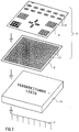
- An input console 1 for a printing press has a rectangular in its inclined surface 2 Well 3, the base 4 horizontally is arranged.
- the base area 4 can, however also be inclined in a user-friendly manner.
- the Base area 4 serves as a support for a digitizing panel executed contact level 6.
- On the Contact level 6 is a command foil 8 arranged as an input field 9. Above the input field 9 is easily readable with the contact level 6 via a control center computer 14 coupled screen 12 is provided.
- the contact level 6 is designed as a switch matrix, and in many small (e.g. 672) contact fields 13 divided.
- the contact fields 13 are with a Processing logic (interface) of the control center computer 14 by means of contact lines 24 (FIG. 2) "Hardware" connected.
- the control of the Processing logic 14 can be binary or other Way coded.
- the subdivision of the contact level 6 allows in many contact fields 13 a change or extension of command fields 16 on the input field 9 without electromechanical Changes are made ought to. It will just be the coding program the processing logic 14 "software" -like recoded.
- the command fields 16 are corresponding marked on the command foil 8 printed on.
- each command field 16 each one or more contact fields according to size 13 assigned.
- the further assignment to the adjusting means 11 of the printing press each of the Contact fields 13 fed to the control center computer 14 Signals are "software" -like. Since one the individual input functions depending of the "software” can arrange arbitrarily arrangement options that only through the available area of input field 9 or of the contact level 6 or by the number of Contact fields 13 are limited. Of course it is also possible the command foil 8 on the contact level 6 attach (e.g. glue on).
- the contact fields 13 are actuated through the command foil 8, e.g. B. means a finger or pen.
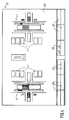
- Fig. 2 shows the mechanical structure of the Contact fields 13 of the contact level 6.
- the contact level 6 consists of a lower conductor foil 22 with switching elements 23 and associated contact lines 24. the connection to the downstream processing logic 14 Establish (interface).
- On the conductor foil 22 e.g. attached a spacer film 26 by means of adhesive, each in the area of the switching elements 23 Breakthrough 27 has.
- On the spacer sheet 26 a further carrier film 28 is attached, which in Area of the openings 27 and switching elements 23 each have a contact grid 29.
- Command field 16 is the one below it Contact grid 29 in contact with each switching element arranged at a distance below 23 brought and triggered an electrical signal, that by means of the contact lines 24 to Processing logic 14 arrives.
- the individual contact fields 13 of the contact level 6 also as capacitive, inductive or piezoelectric Switching elements are executed.
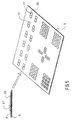
- FIG. 3 shows an example of a command field arrangement on a command sheet 31.
- the command fields 32, 33 in the upper third of the input field 9 serve z. B. to select the different Printing units, folders, dryers or others Peripherals.
- an actuation of Command field 33 for selecting a second Printing unit becomes an image on the screen 12 39 (Fig. 4) with actual values of the various register setting systems the second printing unit.
- the display is both graphical 41, as well as numerically 42.
- the freely assignable command fields F1 - F12 in the middle third of the input field 9 are used to select the desired function according to the function displays 35 at the bottom Image edge of the screen 12.
- the actuation pressure be used as additional input parameters, since the piezo elements depend on the pressure applied different high output voltages produce. So through pressure dosing adjustment processes can also be controlled.
- the command fields 16, 32, 33, 34, F1 - F12, have small ones Beaded 36 around its actuating surface 37, so these actuating surfaces 37 are not inadvertently can be operated.
- the input field 9 corresponds the input field 9 the general safety regulations for printing presses and can therefore also for machine run commands (e.g. B. Advance) can be used.
Landscapes
- Inking, Control Or Cleaning Of Printing Machines (AREA)
- Input From Keyboards Or The Like (AREA)
- Printers Characterized By Their Purpose (AREA)
Claims (4)
- Dispositif pour introduire et afficher, à l'aide de touches, des instructions ou des données pour assurer la commande ou la surveillance d'une machine à imprimer, depuis un pupitre de commande (1) avec une zone d'introduction unique (9) comprenant une représentation schématique des éléments d'impression commandés (1; 2; 3; 4; 5) de la machine à imprimer et un dispositif de sélection (32; 33) pour les éléments d'impression individuels (1; 2; 3; 4; 5), caractérisé en ce que la zone d'introduction (9) est constituée par une feuille de commande (31) avec un certain nombre de zones de sélection (32; 33) représentées graphiquement sous la forme du contour des éléments d'impression (1; 2; 3; 4; 5) et des unités élémentaires (A; P; W) à commander, pour sélectionner les éléments d'impression (1; 2; 3; 4; 5) et les unités individuelles (A; P; W) et un plan de contact (6) disposé sous la feuille de commande (31) avec un certain nombre de zones de contact (13) qui peuvent être commandées au moins depuis l'intérieur de la représentation schématique des éléments d'impression (1; 2; 3; 4; 5) et des unités élémentaires (A; P; W), ce qui permet la commande de tous les éléments d'impression (1; 2; 3; 4; 5) et des unités élémentaires (A; P; W) de la machine d'impression depuis la zone d'introduction unique (9), en ce que les zones de contact (13) sont agencées pour pouvoir être activées à travers la feuille de commande (31), que les zones de commande (13) sont en communication avec un ordinateur (14), qu'un écran de visualisation (12) est prévu, que l'écran dc visualisation (12) est connecté avec l'ordinateur, qu'à la suite d'une commande effectuée par une des zones des contact (13) d'une zone de commande (33), des données graphiques et/ou des données numériques (39) associées avec les zones de contact (33) sont affichées sur l'écran de visualisation (12) et les commandes de contrôle (F1 à F12) associées avec les zones de commande (33) sont effectuées.
- Dispositif selon la revendication 1, caractérisé en ce que la feuille de commande (7; 8; 31) a un support d'information (17) permettant de l'identifier automatiquement.
- Dispositif selon l'une des revendications 1 à 2, caractérisé en ce que l'ordinateur (14) prévu est programmé de manière à ce qu'un mouvement d'activation du plan de contact (6) puisse être converti, en fonction de sa direction et de son importance, en une commande correspondante.
- Dispositif selon les revendications 1 à 3 caractérisé en ce que la feuille de commande (7; 8; 31) a un bourrelet (36) entourant chacune des zones de commande (16; 32; 33; 34; F1 à F12).
Applications Claiming Priority (4)
| Application Number | Priority Date | Filing Date | Title |
|---|---|---|---|
| DE3709872 | 1987-03-27 | ||
| DE3709872 | 1987-03-27 | ||
| DE3805902A DE3805902A1 (de) | 1987-03-27 | 1988-02-25 | Dateneingabe an druckmaschinen |
| DE3805902 | 1988-02-25 |
Publications (4)
| Publication Number | Publication Date |
|---|---|
| EP0284007A2 EP0284007A2 (fr) | 1988-09-28 |
| EP0284007A3 EP0284007A3 (en) | 1990-01-03 |
| EP0284007B1 EP0284007B1 (fr) | 1992-12-16 |
| EP0284007B2 true EP0284007B2 (fr) | 1999-06-02 |
Family
ID=25853909
Family Applications (1)
| Application Number | Title | Priority Date | Filing Date |
|---|---|---|---|
| EP88104518A Expired - Lifetime EP0284007B2 (fr) | 1987-03-27 | 1988-03-22 | Dispositif pour introduire des données dans une machine à imprimer |
Country Status (3)
| Country | Link |
|---|---|
| EP (1) | EP0284007B2 (fr) |
| JP (1) | JP2968273B2 (fr) |
| DE (2) | DE3805902A1 (fr) |
Families Citing this family (11)
| Publication number | Priority date | Publication date | Assignee | Title |
|---|---|---|---|---|
| DE3904702C1 (en) * | 1989-02-16 | 1990-07-26 | Messerschmitt-Boelkow-Blohm Gmbh, 8012 Ottobrunn, De | Keyboard with definable keys |
| DE3906088A1 (de) * | 1989-02-27 | 1990-08-30 | Sigmund Scriba | Eingabegeraet zur eingabe von befehlen in eine datenverarbeitungsanlage |
| DE4014135C1 (en) * | 1989-09-07 | 1990-12-06 | Enno 8053 Attenkirchen De Messerschmitt | Information carrier for data input - has rings with guide profile corresp. to recess in data sheets |
| US5156475A (en) * | 1990-12-06 | 1992-10-20 | Arkady Zilberman | Keyboard divided by central inverted T-shaped entry-space key |
| JPH1145149A (ja) * | 1997-07-28 | 1999-02-16 | Sony Corp | データ表示装置及び方法並びに記録媒体、データ送信装置及び方法 |
| DE29716849U1 (de) * | 1997-09-19 | 1998-05-28 | Siemens Ag | Bedien- und Beobachtungsvorrichtung mit Infrarotsende- und Empfangseinrichtung |
| EP0903653A3 (fr) * | 1997-09-19 | 1999-12-15 | Siemens Aktiengesellschaft | Dispositif de commande et d'observation avec unité d'émetteur et récepteur à infrarouge |
| DE19746323A1 (de) * | 1997-10-21 | 1999-04-22 | Heidelberger Druckmasch Ag | Verfahren und Vorrichtung zum Einschalten einer Maschine |
| DE10163261A1 (de) * | 2001-12-21 | 2003-07-17 | Koenig & Bauer Ag | Simulationssystem für eine Druckmaschine |
| DE102006025141A1 (de) * | 2006-05-30 | 2007-12-06 | BSH Bosch und Siemens Hausgeräte GmbH | Verfahren zur Herstellung eines Blendenteils für ein Bedienpanel mit berührungsempfindlichen Sensortasten, insbesondere für ein Haushaltsgerät |
| DE102007052381A1 (de) | 2007-10-31 | 2009-05-07 | Heidelberger Druckmaschinen Ag | Anzeigevorrichtung für Bedruckstoff verarbeitende Maschinen |
Family Cites Families (7)
| Publication number | Priority date | Publication date | Assignee | Title |
|---|---|---|---|---|
| DE1801696A1 (de) * | 1968-10-08 | 1970-04-23 | Licentia Gmbh | Schalt-Tastaturkonsole |
| US3760360A (en) * | 1971-11-01 | 1973-09-18 | E Systems Inc | Matrix switch |
| US4066850A (en) * | 1976-06-04 | 1978-01-03 | Ncr Corporation | Keyboard switch assembly having interchangeable cover plate, indicating layer and actuator switch assembly in any operative combination |
| JPS57148237U (fr) * | 1981-03-06 | 1982-09-17 | ||
| JPS59139436A (ja) * | 1983-01-31 | 1984-08-10 | Anritsu Corp | 情報入力方法 |
| EP0160167A1 (fr) * | 1984-02-21 | 1985-11-06 | Didde Graphic Systems Corporation | Procédé et appareil de commande électronique distribuée d'une presse à imprimer |
| JPH0721791B2 (ja) * | 1984-05-25 | 1995-03-08 | ソニー株式会社 | グラフ作成装置 |
-
1988
- 1988-02-25 DE DE3805902A patent/DE3805902A1/de not_active Withdrawn
- 1988-03-22 EP EP88104518A patent/EP0284007B2/fr not_active Expired - Lifetime
- 1988-03-22 DE DE8888104518T patent/DE3876659D1/de not_active Expired - Fee Related
- 1988-03-25 JP JP63069946A patent/JP2968273B2/ja not_active Expired - Lifetime
Also Published As
| Publication number | Publication date |
|---|---|
| JPS63255726A (ja) | 1988-10-24 |
| EP0284007A2 (fr) | 1988-09-28 |
| EP0284007B1 (fr) | 1992-12-16 |
| DE3805902A1 (de) | 1988-10-06 |
| JP2968273B2 (ja) | 1999-10-25 |
| EP0284007A3 (en) | 1990-01-03 |
| DE3876659D1 (de) | 1993-01-28 |
Similar Documents
| Publication | Publication Date | Title |
|---|---|---|
| EP0293618B2 (fr) | Dispositif de commande d'une machine | |
| DE19539288C2 (de) | Frei programmierbare Bedienungsplatte für einen Aufzugswagen | |
| EP0284007B2 (fr) | Dispositif pour introduire des données dans une machine à imprimer | |
| DE19731285A1 (de) | Bedienelement | |
| DE19730297A1 (de) | Bedienvorrichtung mit zweidimensionaler Dialogbewegung | |
| CH703401B1 (de) | Verfahren und Vorrichtung zum Erzeugen einer Benutzerschnittstelle zum Bedienen von Maschinen. | |
| EP0378649B1 (fr) | Dispositif pour introduire des donnees de commande dans une machine-outil cnc | |
| EP0236727B1 (fr) | Pupitre de commande pour imprimante, en particulier une imprimante matricielle | |
| DE4413230A1 (de) | Bedienpult für eine Druckmaschine | |
| EP0397092B1 (fr) | Balance électronique avec calculateur de prix | |
| EP1381514B1 (fr) | Dispositif de commande destine a des machines d'impression polychrome | |
| EP0534123A1 (fr) | Clavier de destination et dispositif d'affichage à l'étage pour ascenseurs | |
| DE3700913A1 (de) | Anordnung zum auswaehlen von funktionen | |
| DE3843454C1 (fr) | ||
| DE10317064A1 (de) | Vorrichtungen und Verfahren zur Steuerung einer Anlage | |
| EP2415605A1 (fr) | Poste de conduite d'une presse | |
| EP0990519B1 (fr) | Module de commande pour le dispositif de commande d'une machine à imprimer | |
| EP1433606B1 (fr) | Procédé et dispositif pour commander une machine à imprimer | |
| EP1026041A2 (fr) | Unité de commande, en particulier unité de commande multifonction | |
| DE102005047837A1 (de) | Taktiles Display | |
| DE3314868A1 (de) | Terminal mit einem tasten-bildschirm | |
| DE4120862C2 (de) | Zusatzvorrichtung für ein EDV-Gerät zur Auslösung von Bedienfunktionen | |
| DE4222940A1 (de) | Tastatur mit Maus-Eingabefeld | |
| WO2016102041A1 (fr) | Dispositif de commande pour un véhicule automobile et véhicule automobile | |
| DE19516331C2 (de) | Bedienfeld für eine Druckmaschine |
Legal Events
| Date | Code | Title | Description |
|---|---|---|---|
| PUAI | Public reference made under article 153(3) epc to a published international application that has entered the european phase |
Free format text: ORIGINAL CODE: 0009012 |
|
| AK | Designated contracting states |
Kind code of ref document: A2 Designated state(s): CH DE FR GB IT LI SE |
|
| PUAL | Search report despatched |
Free format text: ORIGINAL CODE: 0009013 |
|
| AK | Designated contracting states |
Kind code of ref document: A3 Designated state(s): CH DE FR GB IT LI SE |
|
| 17P | Request for examination filed |
Effective date: 19900503 |
|
| 17Q | First examination report despatched |
Effective date: 19911122 |
|
| ITF | It: translation for a ep patent filed |
Owner name: DE DOMINICIS & MAYER S.R.L. |
|
| GRAA | (expected) grant |
Free format text: ORIGINAL CODE: 0009210 |
|
| AK | Designated contracting states |
Kind code of ref document: B1 Designated state(s): CH DE FR GB IT LI SE |
|
| GBT | Gb: translation of ep patent filed (gb section 77(6)(a)/1977) |
Effective date: 19921215 |
|
| ET | Fr: translation filed | ||
| REF | Corresponds to: |
Ref document number: 3876659 Country of ref document: DE Date of ref document: 19930128 |
|
| PLBI | Opposition filed |
Free format text: ORIGINAL CODE: 0009260 |
|
| PLBI | Opposition filed |
Free format text: ORIGINAL CODE: 0009260 |
|
| 26 | Opposition filed |
Opponent name: HEIDELBERGER DRUCKMASCHINEN AG Effective date: 19930916 |
|
| 26 | Opposition filed |
Opponent name: MAN ROLAND DRUCKMASCHINEN AG Effective date: 19930915 Opponent name: HEIDELBERGER DRUCKMASCHINEN AG Effective date: 19930916 |
|
| EAL | Se: european patent in force in sweden |
Ref document number: 88104518.1 |
|
| RAP2 | Party data changed (patent owner data changed or rights of a patent transferred) |
Owner name: KOENIG & BAUER-ALBERT AKTIENGESELLSCHAFT |
|
| PLBQ | Unpublished change to opponent data |
Free format text: ORIGINAL CODE: EPIDOS OPPO |
|
| PLAB | Opposition data, opponent's data or that of the opponent's representative modified |
Free format text: ORIGINAL CODE: 0009299OPPO |
|
| R26 | Opposition filed (corrected) |
Opponent name: HEIDELBERGER DRUCKMASCHINEN AG * 930915 MAN ROLAND Effective date: 19930916 |
|
| PLAW | Interlocutory decision in opposition |
Free format text: ORIGINAL CODE: EPIDOS IDOP |
|
| PLAW | Interlocutory decision in opposition |
Free format text: ORIGINAL CODE: EPIDOS IDOP |
|
| RAP2 | Party data changed (patent owner data changed or rights of a patent transferred) |
Owner name: KOENIG & BAUER AKTIENGESELLSCHAFT |
|
| PUAH | Patent maintained in amended form |
Free format text: ORIGINAL CODE: 0009272 |
|
| STAA | Information on the status of an ep patent application or granted ep patent |
Free format text: STATUS: PATENT MAINTAINED AS AMENDED |
|
| 27A | Patent maintained in amended form |
Effective date: 19990602 |
|
| AK | Designated contracting states |
Kind code of ref document: B2 Designated state(s): CH DE FR GB IT LI SE |
|
| GBTA | Gb: translation of amended ep patent filed (gb section 77(6)(b)/1977) | ||
| REG | Reference to a national code |
Ref country code: CH Ref legal event code: AEN Free format text: AUFRECHTERHALTUNG DES PATENTES IN GEAENDERTER FORM |
|
| ET3 | Fr: translation filed ** decision concerning opposition | ||
| ITF | It: translation for a ep patent filed |
Owner name: DE DOMINICIS & MAYER S.R.L. |
|
| PGFP | Annual fee paid to national office [announced via postgrant information from national office to epo] |
Ref country code: DE Payment date: 20000405 Year of fee payment: 13 |
|
| PGFP | Annual fee paid to national office [announced via postgrant information from national office to epo] |
Ref country code: GB Payment date: 20010227 Year of fee payment: 14 |
|
| PGFP | Annual fee paid to national office [announced via postgrant information from national office to epo] |
Ref country code: FR Payment date: 20010321 Year of fee payment: 14 |
|
| PGFP | Annual fee paid to national office [announced via postgrant information from national office to epo] |
Ref country code: SE Payment date: 20010326 Year of fee payment: 14 |
|
| PGFP | Annual fee paid to national office [announced via postgrant information from national office to epo] |
Ref country code: CH Payment date: 20010403 Year of fee payment: 14 |
|
| PG25 | Lapsed in a contracting state [announced via postgrant information from national office to epo] |
Ref country code: DE Free format text: LAPSE BECAUSE OF NON-PAYMENT OF DUE FEES Effective date: 20020101 |
|
| REG | Reference to a national code |
Ref country code: GB Ref legal event code: IF02 |
|
| PG25 | Lapsed in a contracting state [announced via postgrant information from national office to epo] |
Ref country code: GB Free format text: LAPSE BECAUSE OF NON-PAYMENT OF DUE FEES Effective date: 20020322 |
|
| PG25 | Lapsed in a contracting state [announced via postgrant information from national office to epo] |
Ref country code: SE Free format text: LAPSE BECAUSE OF NON-PAYMENT OF DUE FEES Effective date: 20020323 |
|
| PG25 | Lapsed in a contracting state [announced via postgrant information from national office to epo] |
Ref country code: LI Free format text: LAPSE BECAUSE OF NON-PAYMENT OF DUE FEES Effective date: 20020331 Ref country code: CH Free format text: LAPSE BECAUSE OF NON-PAYMENT OF DUE FEES Effective date: 20020331 |
|
| EUG | Se: european patent has lapsed |
Ref document number: 88104518.1 |
|
| GBPC | Gb: european patent ceased through non-payment of renewal fee |
Effective date: 20020322 |
|
| REG | Reference to a national code |
Ref country code: CH Ref legal event code: PL |
|
| PG25 | Lapsed in a contracting state [announced via postgrant information from national office to epo] |
Ref country code: FR Free format text: LAPSE BECAUSE OF NON-PAYMENT OF DUE FEES Effective date: 20021129 |
|
| REG | Reference to a national code |
Ref country code: FR Ref legal event code: ST |
|
| PG25 | Lapsed in a contracting state [announced via postgrant information from national office to epo] |
Ref country code: IT Free format text: LAPSE BECAUSE OF NON-PAYMENT OF DUE FEES;WARNING: LAPSES OF ITALIAN PATENTS WITH EFFECTIVE DATE BEFORE 2007 MAY HAVE OCCURRED AT ANY TIME BEFORE 2007. THE CORRECT EFFECTIVE DATE MAY BE DIFFERENT FROM THE ONE RECORDED. Effective date: 20050322 |
|
| PLAB | Opposition data, opponent's data or that of the opponent's representative modified |
Free format text: ORIGINAL CODE: 0009299OPPO |