EP0293618B2 - Dispositif de commande d'une machine - Google Patents
Dispositif de commande d'une machine Download PDFInfo
- Publication number
- EP0293618B2 EP0293618B2 EP88107127A EP88107127A EP0293618B2 EP 0293618 B2 EP0293618 B2 EP 0293618B2 EP 88107127 A EP88107127 A EP 88107127A EP 88107127 A EP88107127 A EP 88107127A EP 0293618 B2 EP0293618 B2 EP 0293618B2
- Authority
- EP
- European Patent Office
- Prior art keywords
- control
- display
- control elements
- components
- elements
- Prior art date
- Legal status (The legal status is an assumption and is not a legal conclusion. Google has not performed a legal analysis and makes no representation as to the accuracy of the status listed.)
- Expired - Lifetime
Links
Images

Classifications
-
- B—PERFORMING OPERATIONS; TRANSPORTING
- B41—PRINTING; LINING MACHINES; TYPEWRITERS; STAMPS
- B41F—PRINTING MACHINES OR PRESSES
- B41F33/00—Indicating, counting, warning, control or safety devices
- B41F33/0009—Central control units
-
- G—PHYSICS
- G05—CONTROLLING; REGULATING
- G05B—CONTROL OR REGULATING SYSTEMS IN GENERAL; FUNCTIONAL ELEMENTS OF SUCH SYSTEMS; MONITORING OR TESTING ARRANGEMENTS FOR SUCH SYSTEMS OR ELEMENTS
- G05B19/00—Programme-control systems
- G05B19/02—Programme-control systems electric
- G05B19/04—Programme control other than numerical control, i.e. in sequence controllers or logic controllers
- G05B19/10—Programme control other than numerical control, i.e. in sequence controllers or logic controllers using selector switches
- G05B19/106—Programme control other than numerical control, i.e. in sequence controllers or logic controllers using selector switches for selecting a programme, variable or parameter
- G05B19/108—Programme control other than numerical control, i.e. in sequence controllers or logic controllers using selector switches for selecting a programme, variable or parameter characterised by physical layout of switches; switches co-operating with display; use of switches in a special way
-
- Y—GENERAL TAGGING OF NEW TECHNOLOGICAL DEVELOPMENTS; GENERAL TAGGING OF CROSS-SECTIONAL TECHNOLOGIES SPANNING OVER SEVERAL SECTIONS OF THE IPC; TECHNICAL SUBJECTS COVERED BY FORMER USPC CROSS-REFERENCE ART COLLECTIONS [XRACs] AND DIGESTS
- Y02—TECHNOLOGIES OR APPLICATIONS FOR MITIGATION OR ADAPTATION AGAINST CLIMATE CHANGE
- Y02P—CLIMATE CHANGE MITIGATION TECHNOLOGIES IN THE PRODUCTION OR PROCESSING OF GOODS
- Y02P90/00—Enabling technologies with a potential contribution to greenhouse gas [GHG] emissions mitigation
- Y02P90/02—Total factory control, e.g. smart factories, flexible manufacturing systems [FMS] or integrated manufacturing systems [IMS]
Definitions
- the invention relates to a control device Printing machine with a control panel, consisting of from control elements for entering commands and a display device for status display.
- FR-A 2 450 305 is a program control known for a washing machine. To preset the washing machine are a variety of selection keys provided that a corresponding number of Functions of the washing machine are assigned. For example, one of these selector switches is used to select a specific wash program, another is used to select the ones you want Spin speed. This means that with a A large number of functions to be performed Number of selection buttons provided Must be, of course, a considerable effort represents. Furthermore, that in FR-A 2 450 305 serves presented program control only the default a washing machine - subsequent Changes to individual functions are not possible.
- GB-A 2 098 286 describes a device for Regulation of a washing machine described. For this there are two groups of controls, whereby by means of a second group of Controls from operator specifications regarding of the laundry to be treated. An optimal one then takes place under computer control Setting the elements of a first group of controls. This optimal from the computer certain setting is via display elements visualized. The operator has the option here given the displayed positions on request change. There are a corresponding number for this additional controls are provided.
- FR-A 2 098 065 also deals with the default setting of a washing machine. Everyone individual function of the washing machine is each a corresponding selection key is assigned. The default Data is no longer afterwards correctable.
- a device for color control of a Printing machine is from the company information of HEIDELBERGER DRUCKMASCHINEN AG, "Heidelberger horren 3/40" became known.
- the one presented there under the name CPC 1 System includes a control panel for the color guide in a printing press, in which over Control elements color metering elements can be adjusted can. The positions of these color metering elements are shown on an LED display.
- a printing press but also with other types of machines, for example machine tools, however, there are a variety of different ones Machine components before commissioning the machine or even while the machine is running must be adjusted or adjusted. For example, there are a number of actuators present that a particular organ one Press component.
- INFO 7 AG In a publication by MAN Roland Druckmaschinen labeled INFO 7 AG is a control center with a keyboard and several alphanumeric and graphic ones Display elements described.
- the keyboard and display elements are separate arranged from each other. There is no spatial / geometric assignment of the Keyboard elements for the display elements.
- the keyboard contains input keys for Numbers and letters and cursor keys further key groups with special Functions. The functions that can be performed with the button groups are not strictly hierarchical. This object is achieved by a control device which has the features of Claim 1 has.
- Input and display device is the small number of keys or input elements, their assignment is multiple and depending on the selection by the first group of controls due to a Display is made.
- the display immediately shows whether a certain function of the machine switched on or off or has a certain value. For example, with the display also the possibility of an amount of an adjustment path, for example to represent graphically and / or numerically.
- a display device is advantageous provided with which the assignment of the controls displayed in graphical representation becomes. This makes the display language-independent. The symbols are easy to recognize and close incorrect operation due to textual misunderstandings out. It is also possible to add one Image showing the entire component of the machine or the entire machine shows and makes it easier for the operator the commands to be executed for the respective component, or assign to the machine.
- the ad of these components or the machine controlled the selection of the controls, this meant for example, that when you press a key the first group of controls selected main component is displayed, while after pressing one key the second Group of controls the now selected Component is shown as an overall picture.
- a further development of the invention provides a function input that is prompted by command was to execute immediately or just to select and only to be executed if, for example another command is given or the machine is in a certain operating state.
- This so-called preselection of functions is e.g. useful if the machine before Start is set and only at the start of the machine run the presetting can be carried out should.
- Another advantage is according to the training seen in that even if the display fails the machine can be operated because the Key assignment options predefined are and an assignment of the keys by the Pressing certain keys is defined, this can Occupancy either from knowledge of the occupancy scheme or from additional aids, such as. Stencils or the like, determined and thus enables the machine to be operated will.
- Another embodiment of the invention provides the presentation of several components, so that an operator has the option of changing the set Functions of several components simultaneously monitor. It is also provided these functions not only to monitor, but also Switching or setting commands on several at the same time Let components work. Will the establishment applied to a printing press, so it is particularly beneficial to the second group of controls or one of the second Group of control elements connected in parallel the individual printing units of the printing press assign. Every printing unit can use it as a component individually or in total to be chosen.
- the display of the assignment of the key assignment to certain components of the machine in one embodiment of the invention that the representation of the groups of controls on a display or on the outer edges of a Displays are arranged and that of the respective Control element or button adjacent area the respective function or mode of operation or assignment of the control element displays.
- the display simultaneously for service monitoring, i.e. to represent the proper Operating the components or other functions to be provided to facilitate machine service.
- each printing unit or on the paper delivery or the paper system a control panel or a display device be arranged with which an operation or monitoring carried out to this extent can be as the operator at the component located there.
- a control panel or a display device be arranged with which an operation or monitoring carried out to this extent can be as the operator at the component located there.
- This unit can be the one according to the invention
- Control device can be attached, all with this control device Control interventions made on the printing press that are not the color or register control affect.
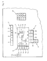
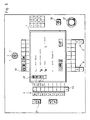
- a display 1 is an operating and display device, which on a control panel of a printing machine is arranged, shown.
- the controls are arranged in groups, a first group Control elements 2 are arranged above the display, is a second group of controls 3 arranged to the side of the display and a third Group of controls 4 is below the display arranged.
- the group of controls 2 can different main groups A, B, C accordingly Numbers 6,7,8 or the machine total 5 selected will.
- the controls 3 can different components of the selected one Main group or the entire machine selected be while using the controls 4 the control, for example the on and off The selected component was switched off will or different functions of selected component can be controlled.
- On input field 25 arranged to the right of display 1 is used for the numerical input of setting data, Quantity data or the like.
- display mode buttons 56 is selected in which display mode Entries should be made. In a first input mode (56, key A) the inputs are transferred directly to the machine, while in a second input mode (56, key B) the entries are saved for the time being and later from the machine be taken over. Furthermore, there is still with a button 9 the possibility of a certain Component a setting on one make certain setting value.
- One control a specific or any component is an example of how the Clarify control device.
- Control element 7 In this example, the controls 2 Main group selected, in which a change should be made. This is done by the actuation, for example of the control element 7.
- the controls can be designed as buttons of course there is also the possibility the controls as non-contact To build sensors or the like.
- the control elements 3 After actuation of the control element 7 are the control elements 3 via the display 1 with certain components the selected main group, i.e. The component X, Component Y via key 11, key 12 Component Z of the selected main group selected will. In this example, the keys are 13 and 14 not assigned components.
- control and display panel is Control of a sheet printing machine shown and is described in more detail below.
- This device also shows an input field for numerical input 25, a key for Machine stop, one emergency stop button, two more Groups of keys 28, 29 and a key switch 55.
- the key group 28 is used to select the individual printing units of the printing press and is each with the printing inks or with others Identifier of the individual printing units.
- the key group 29 contains a key area code 30, an actual value key 31, a service key 34 and a button fault 35.
- the preselection button 29 there is the possibility of certain functional inputs just preselect, with these preselected Functions only at the start or in one certain operating state of the machine switched on will.
- the actual value key 29 actuated then takes place immediately upon entry of the corresponding Function the handover, i.e. the entered Command is executed immediately.
- the service button 34 can switch states of the individual components can be checked.
- Main groups can be controlled using the controls 2 on the press: button 36 denotes the machine as a whole. After actuation Components of the overall machine, such as paper flow, suction air, blown air, Cooling device or cooling in its function, controlled will. With the key 37 the sheet delivery selected as main groups with the key 38 the printing units as a machine element and with the button 39 the feeder as a machine element to be chosen.
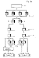
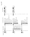
- the flowchart shown in Fig. 3a is intended the operating diagram on the control device or the control panel.
- the control panel i.e. after the start 40 is one of the main groups via the controls 2 or the entire machine selected.
- the following one Forward the function input to the machine immediately (Actual value key 31) or the subsequent input of the function value save first and then close at a certain time, for example at Start the machine to carry out this function setting.
- This preliminary storage requires press the preselection button 30.
- After making this action becomes one of the controls 3 assigned component, which is shown in column 2 of FIG. 3 is listed, selected and / or an adjustment made with the keys 9.9 '.
- Has been the actual value key 31 is pressed then the executed Functions instantly from the press accepted; if the preselection button 30 is pressed the functions performed are grouped into one Cached memory in the control panel and only after certain criteria have been met Hand over printing press.
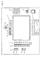
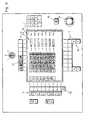
- FIG. 4 is an example of the control for the Boom of a sheet printing machine shown.
- the controls 2 Press key 37 the top one Key of the control elements 3 assigned the number 1, this means that the boom is only one Group of components includes.
- This Group of components is in a schematic representation 15 is displayed.
- This schematic representation includes a representation of the boom and above arranged the functional elements suction roll 41, display fan 42, powdering device 43. IR dryer 44, delivery chain wheel blower 45.
- the preselection key 30 is determined to be a subsequent one Pressing one of the function keys on the Controls 4, is saved for the time being.
- the controls 4 can now be one of the Function elements can be switched on or off.
- the function elements are switched on by Illumination of the corresponding functional element in the schematic representation 15 signals.
- the preset speed is shown on the graphic Display 46 and displayed via an additional numerical display 47.
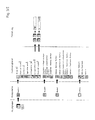
- Fig. 5 shows an example of displaying the paper flow in a sheet-fed printing machine.
- the Total Total (Summe tot ) display shows the total number of prints made by the press, the Total Print Unit ( ⁇ ) display, the prints to be created per print run, the display (V), the speed of the press in hours per hour and the display Sum ( ⁇ 1,2,3 ) the daily output in number of prints.
- control elements 4 the assignment of which is determined in the display 1 by the graphic symbols located above the control elements, the specific function elements can be switched on or off, and the circulation counter can also be set using the 9 'key and the speed using the 9 key be preset on the machine.
Claims (13)
- Dispositif de commande d'une machine à imprimer offset comprenant plusieurs mécanismes d'impression,
se composant d'un pupitre de commande comportant plusieurs groupes d'éléments de manoeuvre pour l'entrée de signaux de commande, ainsi qu'un dispositif d'affichage d'informations alphanumériques et graphiques concernant l'état de la commande, ce dispositif d'affichage étant entouré des éléments de manoeuvre,
caractériséau moins une zone d'affichage (24, 47, 53) de la valeur d'une grandeur d'affichage étant prévue,a) en ce que les éléments de manoeuvre (5, 6, 7, 8) d'un premier groupe (2) d'éléments de manoeuvre ont une affectation prescrite à des groupes principaux pouvant être sélectionnés (A, B, C), l'un des groupes principaux (38) représentant les mécanismes d'impression dans leur ensemble et un autre groupe principal (36) représentant des composants (X, Y, Z) de la machine à imprimer offset qui doivent être commandés et qui sont disposés localement en étant répartis sur la totalité de la machine à imprimer offset,b) en ce que les éléments de manoeuvre (10, 11, 12, 13, 14) d'un deuxième groupe (3) de composants à commander, pouvant être sélectionnés (X, Y, Z), sont associés au groupe principal (A, B, C) pouvant être sélectionné par l'actionnement des éléments de manoeuvre (5, 6, 7, 8) du premier groupe (2),c) en ce que les éléments de manoeuvre (20, 21, 22, 23) d'un troisième groupe (4) sont réalisés pour l'entrée d'instructions de mise en service ou de réglage d'organes fonctionnels (16, 17, 18, 19) afin de déclencher un fonctionnement correspondant des composants (X, Y, Z) sélectionnés par les éléments de manoeuvre (10, 11, 12, 13, 14) du deuxième groupe (3),d) en ce que l'affectation des groupes principaux sélectionnés (A, B, C) des composants (X, Y, Z) et des organes fonctionnels (16, 17, 18, 19) peut être affichée en symboles graphiques correspondants sur le dispositif d'affichage (1).
et les groupes (2, 3, 4) d'éléments de manoeuvre sont disposés sur les côtés extérieurs du dispositif rectangulaire d'affichage (1) de manière que soit visible sur eux l'affectation directe des éléments de manoeuvre aux composants (X, Y, Z) et
des organes fonctionnels (16, 17, 18, 19) aux éléments de manoeuvre par une association en forme de lignes et/ou de colonnes de symboles graphiques pouvant être représentés sur le dispositif d'affichage (1). - Dispositif selon la revendication 1.
caractérisé
en ce que le mode d'entrée est déterminé par d'autres éléments de manoeuvre (56) de manière qu'une instruction entrée de mise en service et/ou une instruction de réglage provoque directement ou uniquement à un état de service déterminé de la machine à imprimer la mise en service ou le réglage des fonctions déterminées. - Dispositif selon la revendication 1 ou 2,
caractérisé
en ce que la machine à imprimer est représentée globalement ou les composants de la machine à imprimer sont représentés graphiquement au moyen du dispositif d'affichage (1). - Dispositif selon la revendication 3,
caractérisé
en ce que l'affichage de la machine à imprimer dans son ensemble ou de ses composants au moyen des éléments de manoeuvre est conçu de manière que l'affichage correspondant ait lieu selon le type de la manipulation à laquelle il faut procéder. - Dispositif selon l'une ou plusieurs des revendications précédentes,
caractérisé
en ce qu'une manipulation de la machine est aussi possible en cas de défaillance du dispositif d'affichage en raison de l'affectation présélectionnable et fixement définie des éléments de manoeuvre. - Dispositif selon l'une ou plusieurs des revendications précédentes,
caractérisé
en ce que des éléments auxiliaires de manoeuvre. à l'aide desquels des processus se déroulant de manière autonome dans la machine à imprimer sont déclenchés, sont prévus en plus des éléments de manoeuvre. - Dispositif selon l'une ou plusieurs des revendications précédentes,
caractérisé
en ce qu'au moins un élément de manoeuvre (52), à l'aide duquel il est procédé simultanément à la représentation de plusieurs composants, est prévu. - Dispositif selon l'une ou plusieurs des revendications précédentes,
caractérisé
en ce qu'au moins un élément de manoeuvre, à l'aide duquel une instruction de mise en service et/ou de réglage agit simultanément sur plusieurs composants, est prévu. - Dispositif selon la revendication 1,
caractérisé
en ce que l'affectation des éléments de manoeuvre est adoptée de manière que l'actionnement des éléments de manoeuvre devant être effectué successivement ait lieu approximativement en arc de cercle dans un sens déterminé autour de l'affichage (1). - Dispositif selon l'une ou plusieurs des revendications précédentes,
caractérisé
en ce qu'au moins un élément de manoeuvre est prévu pour l'initialisation d'un contrôle des états de mise en service des composants et en ce qu'à la suite de l'initialisation, ces états de mise en service et/ou leurs modifications sont affichés sur le dispositif d'affichage (1). - Dispositif selon l'une ou plusieurs des revendications précédentes, qui est conformé en dispositif de la machine à imprimer qui est disposé centralement de manière
qu'au moins un dispositif décentralisé de manoeuvre et d'affichage soit prévu sur des composants individuels de la machine à imprimer tels que l'amenée de papier, le dépôt de papier, un mécanisme d'impression, etc. - Dispositif selon la revendication 11, qui est réalisé sous forme d'un dispositif de la machine à imprimer disposé centralement de manière
qu'une commande de composants déterminés, à laquelle il est procédé au moyen du dispositif décentralisé de manoeuvre, agisse sur le dispositif disposé centralement. - Dispositif selon l'une ou plusieurs des revendications précédentes, qui est conformé en dispositif de la machine à imprimer qui est disposé centralement, de manière
que les entrées dans un pupitre de commande de l'encrage et/ou du repérage agissent sur le dispositif disposé centralement ou que les entrées dans le dispositif disposé centralement agissent sur le pupitre de commande de l'encrage et/ou du repérage.
Applications Claiming Priority (2)
| Application Number | Priority Date | Filing Date | Title |
|---|---|---|---|
| DE3718594 | 1987-06-03 | ||
| DE3718594A DE3718594C3 (de) | 1987-06-03 | 1987-06-03 | Steuerungsvorrichtung einer Druckmaschine |
Publications (3)
| Publication Number | Publication Date |
|---|---|
| EP0293618A1 EP0293618A1 (fr) | 1988-12-07 |
| EP0293618B1 EP0293618B1 (fr) | 1992-08-05 |
| EP0293618B2 true EP0293618B2 (fr) | 1999-11-17 |
Family
ID=6328969
Family Applications (1)
| Application Number | Title | Priority Date | Filing Date |
|---|---|---|---|
| EP88107127A Expired - Lifetime EP0293618B2 (fr) | 1987-06-03 | 1988-05-04 | Dispositif de commande d'une machine |
Country Status (7)
| Country | Link |
|---|---|
| US (1) | US4998472A (fr) |
| EP (1) | EP0293618B2 (fr) |
| JP (1) | JPS645847A (fr) |
| CA (1) | CA1309762C (fr) |
| DE (2) | DE3718594C3 (fr) |
| HK (1) | HK31893A (fr) |
| SG (1) | SG4393G (fr) |
Families Citing this family (35)
| Publication number | Priority date | Publication date | Assignee | Title |
|---|---|---|---|---|
| JP2578789Y2 (ja) * | 1989-09-01 | 1998-08-13 | 東芝機械株式会社 | 印刷装置操作パネル |
| JP2578788Y2 (ja) * | 1989-09-01 | 1998-08-13 | 東芝機械株式会社 | 給紙装置操作パネル |
| JP2586308Y2 (ja) * | 1989-09-01 | 1998-12-02 | 東芝機械株式会社 | 印刷機操作パネル |
| CH681332A5 (fr) * | 1990-04-12 | 1993-02-26 | Gegauf Fritz Ag | |
| DE4013286C2 (de) * | 1990-04-26 | 2001-04-12 | Roland Man Druckmasch | Steuerung für mehrere Druckmaschinen in einem Drucksaal |
| DE9007512U1 (fr) * | 1990-04-26 | 1992-04-02 | Licentia Patent-Verwaltungs-Gmbh, 6000 Frankfurt, De | |
| DE9108716U1 (fr) * | 1991-07-16 | 1991-09-05 | Heidelberger Druckmaschinen Ag, 6900 Heidelberg, De | |
| DE4125137C2 (de) * | 1991-07-30 | 1995-06-14 | Icos Ges Fuer Ind Communicatio | Steuerpult für Bearbeitungs- und Meßmaschinen |
| JP2578173Y2 (ja) * | 1991-08-21 | 1998-08-06 | 株式会社小森コーポレーション | 印刷機械におけるモニタ装置 |
| DE4238259C2 (de) * | 1992-11-12 | 1995-06-22 | Kaltenbach & Voigt | Bedienungsteil für ein Gerät zur medizinischen Behandlung des menschlichen oder tierischen Körpers |
| DE9301390U1 (fr) * | 1993-02-02 | 1993-04-08 | Elektra Beckum Ag, 4470 Meppen, De | |
| DE4314228C2 (de) * | 1993-04-30 | 2002-02-28 | Heidelberger Druckmasch Ag | Verfahren und Einrichtung zur Korrektur des Schrägregisters an Druckmaschinen |
| DE4329886B4 (de) * | 1993-09-06 | 2012-05-03 | Heidelberger Druckmaschinen Ag | Ablaufsteuerungssystem für Druckereien |
| DE19506425B4 (de) * | 1995-02-24 | 2004-11-18 | Heidelberger Druckmaschinen Ag | Offsetdruckverfahren |
| DE29504958U1 (de) * | 1995-03-23 | 1995-05-11 | Siemens Ag | Bediengerät |
| US6243619B1 (en) | 1996-05-10 | 2001-06-05 | Amada Company, Ltd. | Control method and apparatus for plate material processing machine |
| WO1997046926A2 (fr) * | 1996-06-07 | 1997-12-11 | Amada Company, Limited | Procede et dispositif de gestion d'une machine d'usinage de plaque |
| US5917484A (en) * | 1997-02-24 | 1999-06-29 | Hewlett-Packard Company | Multilingual system locale configuration |
| JPH1139030A (ja) * | 1997-07-15 | 1999-02-12 | Tlv Co Ltd | 設備管理装置及び設備管理プログラムを記録したコンピュータ読み取り可能な記録媒体 |
| US5940928A (en) * | 1998-01-15 | 1999-08-24 | Tennant Company | Surface maintenance machine with computer controlled operational and maintenance systems |
| DE19826875A1 (de) * | 1998-06-17 | 1999-12-23 | Heidenhain Gmbh Dr Johannes | Numerische Steuerung mit einem räumlich getrennten Eingabegerät |
| DE19946548A1 (de) | 1999-09-29 | 2001-05-17 | Bosch Gmbh Robert | Verfahren und Vorrichtung zur Auswahl von unterschiedlichen Funktionen zur Realisierung an einem Anschluß einer Steuereinheit |
| DE10056731A1 (de) * | 2000-11-15 | 2002-05-23 | Bosch Gmbh Robert | Vorrichtung für die Bedienung von Steuerungssystemen |
| DE10207871A1 (de) * | 2001-03-29 | 2002-10-10 | Heidelberger Druckmasch Ag | Sicherheitseinrichtung zur Überwachung eines nicht einsehbaren Gefahrenbereichs an einer Druckmaschine |
| FR2840420B1 (fr) * | 2002-05-31 | 2005-05-27 | Sepro Robotique | Dispositif et produit-programme de commande, notamment de manipulateurs ou de robots |
| DE10317065A1 (de) * | 2002-12-16 | 2004-07-22 | Koenig & Bauer Ag | Verfahren und Vorrichtung zur Steuerung und Verfahren zum Konfigurieren einer Anlage |
| EP1433606B1 (fr) | 2002-12-16 | 2008-12-31 | Koenig & Bauer Aktiengesellschaft | Procédé et dispositif pour commander une machine à imprimer |
| WO2008095557A1 (fr) * | 2007-02-05 | 2008-08-14 | Koenig & Bauer Aktiengesellschaft | Procédé de démontage et/ou de montée en régime d'une presse rotative |
| DE102007000952A1 (de) * | 2007-09-20 | 2009-04-02 | Koenig & Bauer Aktiengesellschaft | Verfahren zum Hochlauf einer Rotationsdruckmaschine |
| DE102007028970A1 (de) * | 2007-06-23 | 2008-12-24 | Manroland Ag | Druckmaschinenleitstand |
| JP4723601B2 (ja) * | 2008-02-18 | 2011-07-13 | 三菱重工印刷紙工機械株式会社 | 輪転印刷機および表示装置の表示制御方法 |
| EP2133765B1 (fr) * | 2008-06-11 | 2019-11-27 | Siemens Aktiengesellschaft | Interface utilisateur et son procédé |
| JP5391674B2 (ja) * | 2008-12-04 | 2014-01-15 | パナソニック株式会社 | 電子部品実装用装置のユーザインタフェイスシステム及び電子部品実装用装置 |
| JP2011067954A (ja) * | 2009-09-23 | 2011-04-07 | Ryobi Ltd | 印刷機 |
| JP6666236B2 (ja) * | 2016-12-19 | 2020-03-13 | 日立Geニュークリア・エナジー株式会社 | ディスプレイのユーザーインターフェース装置 |
Family Cites Families (16)
| Publication number | Priority date | Publication date | Assignee | Title |
|---|---|---|---|---|
| DE1513303B2 (de) * | 1965-08-10 | 1971-11-04 | Licentia Patent-Verwaltungs-Gmbh, 6000 Frankfurt | Einzelschaltersteuerung fuer warten von kraftwerken umspann ungswerken und netzen |
| DE2036111C2 (de) * | 1970-07-16 | 1984-01-26 | Bosch-Siemens Hausgeräte GmbH, 7000 Stuttgart | Waschmaschine mit einer Vorrichtung zum automatischen Steuern |
| US4185282A (en) * | 1977-06-02 | 1980-01-22 | Am International, Inc. | Displayed keyboard indicia |
| FR2409339A1 (fr) * | 1977-11-16 | 1979-06-15 | Amiens Const Elect Mec | Machine a laver a manoeuvre se referant a la nature des objets a laver |
| SE444738B (sv) * | 1978-02-14 | 1986-04-28 | Bauknecht Gmbh G | Programindikeringsanordning for hushallsapparater, serskilt hushallstvettmaskiner, torktumlare och diskmaskiner |
| FR2450305A1 (fr) * | 1979-03-02 | 1980-09-26 | Martin Usines Fonderies Arthur | Dispositif hybride de programmation pour machine a laver le linge |
| JPS5672449A (en) * | 1979-11-15 | 1981-06-16 | Minolta Camera Co Ltd | Operating device of copying machine or the like |
| DD150026A1 (de) * | 1980-04-10 | 1981-08-12 | Max Janicki | Steuereinrichtung fuer soll-und/oder istwerte zur farbwerksvoreinstellung |
| DE3149702C1 (de) * | 1981-12-15 | 1989-09-21 | Bosch-Siemens Hausgeräte GmbH, 7000 Stuttgart | Programmwahl-Eingabetastatur fuer ein programmgesteuertes Haushaltsgeraet |
| DE3219293A1 (de) * | 1982-05-22 | 1983-11-24 | Thomas 7000 Stuttgart Schönherr | Vorrichtung zum vorzugsweise wahlweisen schalten bzw. an- und aussteuern von elektrischen geraeten, insbesondere der unterhaltungselektronik |
| DE3220378C2 (de) * | 1982-05-29 | 1994-03-03 | Heidelberger Druckmasch Ag | Steuervorrichtung für eine Druckmaschine |
| JPS5999536A (ja) * | 1982-11-29 | 1984-06-08 | Sanyo Electric Co Ltd | 電子機器 |
| JPH0736123B2 (ja) * | 1983-05-09 | 1995-04-19 | 株式会社日立製作所 | 設備群制御方法 |
| US4709635A (en) * | 1984-07-11 | 1987-12-01 | Harris Graphics Corporation | Fluid metering method and apparatus |
| DE3672848D1 (de) * | 1985-02-06 | 1990-08-30 | Toshiba Kawasaki Kk | Bilderzeugungsgeraet mit bedienungspultkontrollfunktion. |
| DD234831A1 (de) * | 1985-02-27 | 1986-04-16 | Polygraph Leipzig | Steuersystem fuer druckmaschinen |
-
1987
- 1987-06-03 DE DE3718594A patent/DE3718594C3/de not_active Expired - Fee Related
-
1988
- 1988-04-29 CA CA000565530A patent/CA1309762C/fr not_active Expired - Lifetime
- 1988-05-04 EP EP88107127A patent/EP0293618B2/fr not_active Expired - Lifetime
- 1988-05-04 DE DE8888107127T patent/DE3873420D1/de not_active Expired - Lifetime
- 1988-06-03 JP JP63135775A patent/JPS645847A/ja active Pending
-
1990
- 1990-07-23 US US07/560,234 patent/US4998472A/en not_active Expired - Lifetime
-
1993
- 1993-01-09 SG SG43/93A patent/SG4393G/en unknown
- 1993-04-01 HK HK318/93A patent/HK31893A/xx not_active IP Right Cessation
Also Published As
| Publication number | Publication date |
|---|---|
| CA1309762C (fr) | 1992-11-03 |
| US4998472A (en) | 1991-03-12 |
| JPS645847A (en) | 1989-01-10 |
| SG4393G (en) | 1993-03-12 |
| DE3873420D1 (de) | 1992-09-10 |
| DE3718594A1 (de) | 1988-12-22 |
| EP0293618A1 (fr) | 1988-12-07 |
| HK31893A (en) | 1993-04-08 |
| EP0293618B1 (fr) | 1992-08-05 |
| DE3718594C2 (de) | 1994-08-11 |
| DE3718594C3 (de) | 2001-01-18 |
Similar Documents
| Publication | Publication Date | Title |
|---|---|---|
| EP0293618B2 (fr) | Dispositif de commande d'une machine | |
| EP1620265B1 (fr) | Systeme pour inspecter une impression | |
| AT391109B (de) | Einrichtung zur korrektur der farbgebung bei druckmaschinen | |
| EP0531675B1 (fr) | Procédé et dispositif pour régler les vis des zones d'encrage dans leurs positions respectives | |
| EP0979172A1 (fr) | Procede d'exploitation d'une imprimante ou d'une photocopieuse a grande vitesse avec instructions sur la procedure a suivre en cas d'incidents | |
| DE19856675A1 (de) | Automatische Seitenidentifikation | |
| DE3220622A1 (de) | Dateneingabeeinrichtung an druckmaschinen | |
| EP0023299A1 (fr) | Procédé et dispositif pour ajuster le registre de machines à imprimer en creux | |
| DE10052014B4 (de) | Verfahren zum Steuern und Aktualisieren des Bediensystems für eine Druckmaschine | |
| DE4314228C2 (de) | Verfahren und Einrichtung zur Korrektur des Schrägregisters an Druckmaschinen | |
| DE4329886B4 (de) | Ablaufsteuerungssystem für Druckereien | |
| EP0718801B1 (fr) | Interface utelisateur pour une machine à affranchir | |
| EP0284007B2 (fr) | Dispositif pour introduire des données dans une machine à imprimer | |
| DE3719817C2 (fr) | ||
| DE102005050538B4 (de) | Verfahren zur Vorbereitung und Disposition von Druckaufträgen | |
| DE10317064A1 (de) | Vorrichtungen und Verfahren zur Steuerung einer Anlage | |
| EP0611650B1 (fr) | Système d'affichage pour la trajectoire des bandes | |
| EP1362268B1 (fr) | Contrôle de fonctionnalité d'une unité de machine d'imprimerie | |
| EP0990519B1 (fr) | Module de commande pour le dispositif de commande d'une machine à imprimer | |
| EP1864809B1 (fr) | Dispositif de contrôle d'une machine à imprimer | |
| DD234831A1 (de) | Steuersystem fuer druckmaschinen | |
| EP0207175A1 (fr) | Machine à découper avec un dispositif de commande à ordinateur | |
| EP2453327A2 (fr) | Commande de machines dotée d'un navigateur | |
| DE102005040454A1 (de) | Verfahren zur Markierung von Probebogen | |
| DD239985A1 (de) | Ablaufsteuerung fuer druckmaschinen |
Legal Events
| Date | Code | Title | Description |
|---|---|---|---|
| PUAI | Public reference made under article 153(3) epc to a published international application that has entered the european phase |
Free format text: ORIGINAL CODE: 0009012 |
|
| 17P | Request for examination filed |
Effective date: 19880504 |
|
| AK | Designated contracting states |
Kind code of ref document: A1 Designated state(s): CH DE FR GB IT LI SE |
|
| 17Q | First examination report despatched |
Effective date: 19900514 |
|
| GRAA | (expected) grant |
Free format text: ORIGINAL CODE: 0009210 |
|
| AK | Designated contracting states |
Kind code of ref document: B1 Designated state(s): CH DE FR GB IT LI SE |
|
| REF | Corresponds to: |
Ref document number: 3873420 Country of ref document: DE Date of ref document: 19920910 |
|
| ITF | It: translation for a ep patent filed |
Owner name: STUDIO JAUMANN |
|
| GBT | Gb: translation of ep patent filed (gb section 77(6)(a)/1977) | ||
| ET | Fr: translation filed | ||
| PLBI | Opposition filed |
Free format text: ORIGINAL CODE: 0009260 |
|
| PLBI | Opposition filed |
Free format text: ORIGINAL CODE: 0009260 |
|
| 26 | Opposition filed |
Opponent name: OCE-NEDERLAND B.V. Effective date: 19930402 |
|
| 26 | Opposition filed |
Opponent name: MAN ROLAND DRUCKMASCHINEN AG Effective date: 19930429 Opponent name: OCE-NEDERLAND B.V. Effective date: 19930402 |
|
| EAL | Se: european patent in force in sweden |
Ref document number: 88107127.8 |
|
| PGFP | Annual fee paid to national office [announced via postgrant information from national office to epo] |
Ref country code: SE Payment date: 19960510 Year of fee payment: 9 |
|
| PG25 | Lapsed in a contracting state [announced via postgrant information from national office to epo] |
Ref country code: SE Effective date: 19970505 |
|
| PLAW | Interlocutory decision in opposition |
Free format text: ORIGINAL CODE: EPIDOS IDOP |
|
| APAC | Appeal dossier modified |
Free format text: ORIGINAL CODE: EPIDOS NOAPO |
|
| APAE | Appeal reference modified |
Free format text: ORIGINAL CODE: EPIDOS REFNO |
|
| EUG | Se: european patent has lapsed |
Ref document number: 88107127.8 |
|
| APAC | Appeal dossier modified |
Free format text: ORIGINAL CODE: EPIDOS NOAPO |
|
| PLAW | Interlocutory decision in opposition |
Free format text: ORIGINAL CODE: EPIDOS IDOP |
|
| PGFP | Annual fee paid to national office [announced via postgrant information from national office to epo] |
Ref country code: CH Payment date: 19990616 Year of fee payment: 12 |
|
| PUAH | Patent maintained in amended form |
Free format text: ORIGINAL CODE: 0009272 |
|
| STAA | Information on the status of an ep patent application or granted ep patent |
Free format text: STATUS: PATENT MAINTAINED AS AMENDED |
|
| 27A | Patent maintained in amended form |
Effective date: 19991117 |
|
| AK | Designated contracting states |
Kind code of ref document: B2 Designated state(s): CH DE FR GB IT LI SE |
|
| REG | Reference to a national code |
Ref country code: CH Ref legal event code: AEN Free format text: AUFRECHTERHALTUNG DES PATENTES IN GEAENDERTER FORM |
|
| ET3 | Fr: translation filed ** decision concerning opposition | ||
| ITF | It: translation for a ep patent filed |
Owner name: STUDIO JAUMANN P. & C. S.N.C. |
|
| GBTA | Gb: translation of amended ep patent filed (gb section 77(6)(b)/1977) | ||
| PG25 | Lapsed in a contracting state [announced via postgrant information from national office to epo] |
Ref country code: LI Free format text: LAPSE BECAUSE OF NON-PAYMENT OF DUE FEES Effective date: 20000531 Ref country code: CH Free format text: LAPSE BECAUSE OF NON-PAYMENT OF DUE FEES Effective date: 20000531 |
|
| REG | Reference to a national code |
Ref country code: CH Ref legal event code: PL |
|
| REG | Reference to a national code |
Ref country code: GB Ref legal event code: IF02 |
|
| AK | Designated contracting states |
Designated state(s): AT BE CH CY DE DK ES FI FR GB GR IE IT LI LU MC NL PT SE TR |
|
| AX | Request for extension of the european patent |
Extension state: AL LT LV MK RO SI |
|
| 18W | Application withdrawn |
Effective date: 20030207 |
|
| D17D | Deferred search report published (deleted) | ||
| DA1 | Application published (deleted) | ||
| PGFP | Annual fee paid to national office [announced via postgrant information from national office to epo] |
Ref country code: GB Payment date: 20030422 Year of fee payment: 16 |
|
| PGFP | Annual fee paid to national office [announced via postgrant information from national office to epo] |
Ref country code: FR Payment date: 20031022 Year of fee payment: 16 |
|
| PG25 | Lapsed in a contracting state [announced via postgrant information from national office to epo] |
Ref country code: GB Free format text: LAPSE BECAUSE OF NON-PAYMENT OF DUE FEES Effective date: 20040504 |
|
| GBPC | Gb: european patent ceased through non-payment of renewal fee |
Effective date: 20040504 |
|
| PG25 | Lapsed in a contracting state [announced via postgrant information from national office to epo] |
Ref country code: FR Free format text: LAPSE BECAUSE OF NON-PAYMENT OF DUE FEES Effective date: 20050131 |
|
| REG | Reference to a national code |
Ref country code: FR Ref legal event code: ST |
|
| PG25 | Lapsed in a contracting state [announced via postgrant information from national office to epo] |
Ref country code: IT Free format text: LAPSE BECAUSE OF NON-PAYMENT OF DUE FEES;WARNING: LAPSES OF ITALIAN PATENTS WITH EFFECTIVE DATE BEFORE 2007 MAY HAVE OCCURRED AT ANY TIME BEFORE 2007. THE CORRECT EFFECTIVE DATE MAY BE DIFFERENT FROM THE ONE RECORDED. Effective date: 20050504 |
|
| APAH | Appeal reference modified |
Free format text: ORIGINAL CODE: EPIDOSCREFNO |
|
| PGFP | Annual fee paid to national office [announced via postgrant information from national office to epo] |
Ref country code: DE Payment date: 20060707 Year of fee payment: 19 |
|
| PG25 | Lapsed in a contracting state [announced via postgrant information from national office to epo] |
Ref country code: DE Free format text: LAPSE BECAUSE OF NON-PAYMENT OF DUE FEES Effective date: 20071201 |
|
| PLAB | Opposition data, opponent's data or that of the opponent's representative modified |
Free format text: ORIGINAL CODE: 0009299OPPO |