EP0283049B1 - Arrangement de circuit pour contrôler le démarrage et le freinage des moteurs asynchrones à courant triphasé et procédé pour mettre en oeuvre un tel arrangement de circuit - Google Patents
Arrangement de circuit pour contrôler le démarrage et le freinage des moteurs asynchrones à courant triphasé et procédé pour mettre en oeuvre un tel arrangement de circuit Download PDFInfo
- Publication number
- EP0283049B1 EP0283049B1 EP88104423A EP88104423A EP0283049B1 EP 0283049 B1 EP0283049 B1 EP 0283049B1 EP 88104423 A EP88104423 A EP 88104423A EP 88104423 A EP88104423 A EP 88104423A EP 0283049 B1 EP0283049 B1 EP 0283049B1
- Authority
- EP
- European Patent Office
- Prior art keywords
- circuit arrangement
- braking
- output
- rotary speed
- actual
- Prior art date
- Legal status (The legal status is an assumption and is not a legal conclusion. Google has not performed a legal analysis and makes no representation as to the accuracy of the status listed.)
- Expired - Lifetime
Links
Images

Classifications
-
- H—ELECTRICITY
- H02—GENERATION; CONVERSION OR DISTRIBUTION OF ELECTRIC POWER
- H02P—CONTROL OR REGULATION OF ELECTRIC MOTORS, ELECTRIC GENERATORS OR DYNAMO-ELECTRIC CONVERTERS; CONTROLLING TRANSFORMERS, REACTORS OR CHOKE COILS
- H02P3/00—Arrangements for stopping or slowing electric motors, generators, or dynamo-electric converters
- H02P3/06—Arrangements for stopping or slowing electric motors, generators, or dynamo-electric converters for stopping or slowing an individual dynamo-electric motor or dynamo-electric converter
- H02P3/18—Arrangements for stopping or slowing electric motors, generators, or dynamo-electric converters for stopping or slowing an individual dynamo-electric motor or dynamo-electric converter for stopping or slowing an ac motor
- H02P3/24—Arrangements for stopping or slowing electric motors, generators, or dynamo-electric converters for stopping or slowing an individual dynamo-electric motor or dynamo-electric converter for stopping or slowing an ac motor by applying dc to the motor
-
- H—ELECTRICITY
- H02—GENERATION; CONVERSION OR DISTRIBUTION OF ELECTRIC POWER
- H02P—CONTROL OR REGULATION OF ELECTRIC MOTORS, ELECTRIC GENERATORS OR DYNAMO-ELECTRIC CONVERTERS; CONTROLLING TRANSFORMERS, REACTORS OR CHOKE COILS
- H02P1/00—Arrangements for starting electric motors or dynamo-electric converters
- H02P1/16—Arrangements for starting electric motors or dynamo-electric converters for starting dynamo-electric motors or dynamo-electric converters
- H02P1/26—Arrangements for starting electric motors or dynamo-electric converters for starting dynamo-electric motors or dynamo-electric converters for starting an individual polyphase induction motor
- H02P1/28—Arrangements for starting electric motors or dynamo-electric converters for starting dynamo-electric motors or dynamo-electric converters for starting an individual polyphase induction motor by progressive increase of voltage applied to primary circuit of motor
Definitions
- the invention relates to a circuit arrangement for controlling the starting and braking of three-phase asynchronous motors according to the preamble of claim 1 and a method for operating such a circuit arrangement.
- a circuit arrangement according to the preamble of claim 1 and a method according to the preamble of claim 4 are also known from US-A-3 866 097.
- Such a circuit arrangement makes it possible to combine the favorable properties of a soft start circuit known per se with minimal structural complexity with the properties of known brake circuits, with completely new possibilities opening up on the control side.
- the invention has for its object to develop such a circuit arrangement or the corresponding operating method so that the fastest and most accurate positioning can be achieved when braking.
- the solution according to the invention ensures that path errors are corrected during the positioning or braking process and accordingly do not reproduce, i.e. in particular, fluctuations in the output speed, load influences, errors in the speed control loop and mains voltage fluctuations are compensated for.
- the switchover device provided according to claim 2 together with a further switchover device which interrupts the speed control loop, achieves a switchover to the “braking and positioning” operating state.
- the further difference-forming device provided according to claim 3 is required for subtracting the remaining distance if braking is to be carried out not to a standstill but to a low positioning speed within a certain distance.
- a root function is preferably provided as the braking curve, since a constant braking acceleration is then achieved.
- a deviation from such a root curve can be provided or, depending on the requirements of the respective application, a respectively suitable braking curve can be freely programmed.
- a very particularly advantageous braking behavior is achieved by the mode of operation provided in accordance with claim 6 in conjunction with the travel-dependent control in accordance with claim 4.
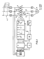
- FIG. 1 an embodiment is shown schematically, which enables a reversal of the direction of rotation.
- a synchronization transformer 1 is used for the voltage supply.
- a switching device 2 in the form of an analog multiplex device connects to its output. This switching device operates as a function of a device 3 which is connected to two outputs of the transformer 1, the device 3 being a circuit arrangement for detecting the phase sequence at the feed terminals L1, L2 and L3, and this circuit arrangement is connected in the exemplary embodiment with two outputs U22 and U13 of the transformer 1.
- the switchover device 2 in connection with the device 3 for detecting the phase position also enables the direction of rotation to be switched over in conjunction with reversing contactors 4, 5. If such a reversal of the direction of rotation is not required, the devices 2, 3 and the reversing contactors 4, 5 can be omitted.
- the outputs of the switching device 2 (or without reversing the direction of rotation of the transformer 1) are connected to a limiting device 6, which in turn is followed by smoothing devices 7 and a comparator 8.
- the synchronization signals are compared with the signals present at the control input 9.
- Ignition devices 10 for phase gating controls 11, 12 and 13 are connected downstream of the comparator 8. The action of these ignition devices 10 on the phase gating controls 11, 12 and 13 is illustrated by the dashed line 14.
- Each phase control 11, 12, 13 is connected upstream of a terminal T 1, T 2, T 3 of the three-phase squirrel-cage motor 15 to be controlled.
- each phase control 11 or 12 or 13 consists of two thyristors 16, 17 or 18, 19 or 20, 21 connected in anti-parallel.
- thyristors 17, 19, 21 and 16, 18, 20 each to be replaced by diodes.
- the braking device is essentially formed by a thyristor 27, which is arranged between the phase control 11, 12 downstream of this.
- the thyristor 27 is ignited by an ignition device 28, which is arranged downstream of a circuit arrangement 29 for the synchronization of the switchover between driving and braking.
- Inputs of this circuit arrangement 29 are connected on the one hand to the outputs U31 and U13 of the transformer 1 or the switching device 2 and on the other hand to a limit value signaling device 30 for determining the switching state "driving" or "braking", this limit value signaling device in turn being connected to the output of the amount forming device 24 is connected.
- the ignition pulses from the ignition device 10 are first blocked for the thyristors 16 to 21 of the phase control 11, 12 and 13 and the deletion time of the thyristors is waited for (at a mains frequency of 50 Hz, 25 ms).
- the thyristor 27, which is used as a switchable semiconductor component in the exemplary embodiment is switched through with the aid of the ignition device 28 and a thyristor acting as a brake thyristor, for example the thyristor 16, is likewise ignited by means of the ignition device 10.
- a DC voltage is applied to the motor winding, which leads to the formation of a DC current along the arrows 31.
- the ignition of the diode 27 creates a freewheeling current in the direction of the arrow 32 during the negative half-wave of the brake thyristor 16.
- the corresponding direct current flowing due to the induction in the windings of the rotating rotor, leads to a current such that a braking effect occurs.
- the DC voltage can be tapped from the transformer 1 if this is followed by a rectifier (not shown in the drawing) and optionally smoothing elements.
- FIG. 2 shows a circuit arrangement according to the invention, in which the circuit arrangement shown in FIG. 1 is used for a positioning drive.
- the right half of the block diagram according to FIG. 2 essentially corresponds to the circuit arrangement shown in FIG. 1 and described in connection with this.
- a speed sensor 33 is provided on the motor 15 and is connected to a speed detection device 34.
- the speed detection device 34 is connected on the one hand to a monitoring device 35, which is connected upstream of the control outputs 36, and on the other hand to the output of the ramp generator 23 or the input of a speed controller 37.
- the changeover switch 25 When switching to the braking or positioning state, the changeover switch 25 is actuated, as a result of which the ramp-function generator 23 is disconnected and the speed control circuit is disconnected.
- the speed detection device 34 is connected to an integration device 40, which acts as an actual displacement sensor and which integrates the rotation speed signal into a displacement signal. Its output 41 is connected to a difference-forming device 42, whose other input is connected to a specification device 43, in the exemplary embodiment a potentiometer, for specifying the desired positioning path after reaching a proximity switch 2.
- An actual distance-to-go signal is formed in the difference-forming device 42, which is connected downstream of a specification device 44 for the desired speed n.
- the specification device 44 can be formed, for example, by a microprocessor in which a braking curve is stored in the form of a predefined dependency of the rotational speed on the remaining distance. This curve can, for example, be designed as a root function, as a result of which constant acceleration is achieved.
- the output 45 of the specification device 44 is connected to the input 46 of the speed controller 37, so that the speed controller 37 is given a speed value in accordance with the specified braking curve.
- the difference-forming device 49 is used for this, which corrects the distance-to-go signal corresponding to the distance between the point at which the positioning speed is to be reached and the point of the final standstill.
Claims (6)
- Agencement de circuit pour la commande du démarrage et du freinage de moteurs asynchrones à courant triphasé, dans lequel au moins deux phases d'une commande de réglage de phase sont situées dans les lignes d'alimentation (L1, L2, L3) du moteur, chaque commande de réglage de phase présentant au moins un thyristor commandé par un dispositif de commande, et dans lequel il est prévu entre les lignes de deux phases d'alimentation (T₁, T₂) du moteur (L1, L2, L3) après au moins deux commandes de réglage de phase (11, 12) une ligne de raccordement dans laquelle est monté un composant semiconducteur commutable faisant fonction de redresseur, caractérisé en ce qu'un dispositif d'intégration (40) faisant fonction de capteur de distance effective est monté en aval d'un dispositif de détection de vitesse (34), la sortie (41) du dispositif d'intégration étant reliée à un dispositif de soustraction (42) dont l'autre entrée est connectée à un dispositif de prédétermination de temps alloué (43) pour prédéfinir la distance prescrite du positionnement après avoir atteint un détecteur de proximité, en ce qu'un dispositif de prédétermination du temps alloué (44) pour la vitesse prescrite (n) en fonction de la distance restante (s') est monté en aval de la sortie du dispositif de soustraction (42) produisant un signal de distance restante effective, et en ce que la sortie (45) de ce dispositif de prédétermination du temps alloué (44) est relié à l'entrée (46) du régulateur de vitesse (37).
- Agencement de circuit selon la revendication 1, caractérisé en ce qu'un dispositif commutateur (25) est monté en amont de l'entrée (46) du régulateur de vitesse (37), entre la sortie (48) d'un capteur d'accélération (23) et la sortie (45) du dispositif de prédétermination du temps alloué (44).
- Agencement de circuit selon la revendication 1 ou la revendication 2, caractérisé en ce qu'un dispositif de soustraction (49), monté en aval du dispositif de prédétermination du temps alloué (44) est relié à un dispositif commutateur (22) pour le passage à une vitesse de positionnement.
- Procédé pour la commande du freinage de moteurs asynchrones à courant triphasé faisant appel à un agencement de circuit selon l'une quelconque des revendications 1 à 3, dans lequel la vitesse effective est détectée ainsi qu'un signal de valeur prescrite de vitesse est formé et amené à un régulateur de vitesse, caractérisé en ce que le signal de sortie est intégré à la vitesse effective pour former un signal de distance effective, en ce que le signal de distance effective est comparé à un signal de distance de positionnement de consigne et en ce que le signal de valeur prescrite de vitesse est formé en fonction d'une courbe de freinage prédéterminée (vitesse en fonction de la distance restante).
- Procédé selon la revendication 4, caractérisé en ce qu'une fonction racine est prédéterminée en tant que courbe de freinage.
- Procédé selon la revendication 4 ou la revendication 5, caractérisé en ce que pour la commutation de l'entraînement en freinage, les impulsions d'amorçage pour les thyristors des commandes de réglage de phase sont verrouillées, et en ce que le temps de désamorçage des thyristors est attendu, et en ce qu'alors le composant semiconducteur présent dans la ligne de raccordement est commuté et qu'un thyristor de la commande de réglage de phase faisant fonction de thyristor de freinage est amorcé.
Priority Applications (1)
| Application Number | Priority Date | Filing Date | Title |
|---|---|---|---|
| AT88104423T ATE77020T1 (de) | 1987-03-20 | 1988-03-19 | Schaltungsanordnung zur steuerung des anlaufens und abbremsens von drehstrom-asynchronmotoren und verfahren zum betrieb einer derartigen schaltungsanordnung. |
Applications Claiming Priority (2)
| Application Number | Priority Date | Filing Date | Title |
|---|---|---|---|
| DE19873709223 DE3709223A1 (de) | 1987-03-20 | 1987-03-20 | Schaltungsanordnung zur steuerung des anlaufens und abbremsens von drehstrom-asynchronmotoren und verfahren zum betrieb einer derartigen schaltungsanordnung |
| DE3709223 | 1987-03-20 |
Publications (3)
| Publication Number | Publication Date |
|---|---|
| EP0283049A2 EP0283049A2 (fr) | 1988-09-21 |
| EP0283049A3 EP0283049A3 (en) | 1989-05-03 |
| EP0283049B1 true EP0283049B1 (fr) | 1992-06-03 |
Family
ID=6323612
Family Applications (1)
| Application Number | Title | Priority Date | Filing Date |
|---|---|---|---|
| EP88104423A Expired - Lifetime EP0283049B1 (fr) | 1987-03-20 | 1988-03-19 | Arrangement de circuit pour contrôler le démarrage et le freinage des moteurs asynchrones à courant triphasé et procédé pour mettre en oeuvre un tel arrangement de circuit |
Country Status (3)
| Country | Link |
|---|---|
| EP (1) | EP0283049B1 (fr) |
| AT (1) | ATE77020T1 (fr) |
| DE (2) | DE3709223A1 (fr) |
Families Citing this family (6)
| Publication number | Priority date | Publication date | Assignee | Title |
|---|---|---|---|---|
| DE9007406U1 (fr) * | 1990-03-21 | 1991-08-22 | Truetzschler Gmbh & Co Kg, 4050 Moenchengladbach, De | |
| DE4312549C2 (de) * | 1993-04-17 | 1995-04-13 | Licentia Gmbh | Verfahren zur Drehmomentbegrenzung beim Sanftanlauf von Drehstromasynchronmotoren |
| DE4431376C1 (de) * | 1994-08-29 | 1995-12-21 | Mannesmann Ag | Positionierregelkreis |
| EP0791875A1 (fr) * | 1996-02-24 | 1997-08-27 | Fachhochschule Konstanz | Système d'entraînement pour dispositifs de levage et machines-outil |
| DE19725786C1 (de) * | 1997-06-18 | 1999-02-04 | Hartmann & Braun Gmbh & Co Kg | Steuerung für einen umrichtergespeisten Asynchronmotor in einem Stellantrieb |
| CN101917147B (zh) * | 2010-08-20 | 2012-03-07 | 西安西驰电气有限责任公司 | 基于固态软起动器的电机柔性制动控制及零速检测系统 |
Family Cites Families (4)
| Publication number | Priority date | Publication date | Assignee | Title |
|---|---|---|---|---|
| JPS4950708U (fr) * | 1972-08-10 | 1974-05-04 | ||
| DE2659540A1 (de) * | 1976-12-30 | 1978-07-06 | Volker Teichmann | Schaltungsanordnung zur drehzahlregelung eines dreh- bzw. wechselstrommotors |
| JPS5950590B2 (ja) * | 1977-04-15 | 1984-12-08 | 三菱電機株式会社 | 交流エレベ−タの速度制御装置 |
| DE3533802A1 (de) * | 1985-09-21 | 1987-03-26 | Omikron Industrieelektronik | Schaltungsanordnung zur steuerung des anlaufens und abbremsens von drehstrom-asynchronmotoren und verfahren zum betrieb einer derartigen schaltungsanordnung |
-
1987
- 1987-03-20 DE DE19873709223 patent/DE3709223A1/de not_active Withdrawn
-
1988
- 1988-03-19 DE DE8888104423T patent/DE3871570D1/de not_active Expired - Fee Related
- 1988-03-19 AT AT88104423T patent/ATE77020T1/de not_active IP Right Cessation
- 1988-03-19 EP EP88104423A patent/EP0283049B1/fr not_active Expired - Lifetime
Also Published As
| Publication number | Publication date |
|---|---|
| ATE77020T1 (de) | 1992-06-15 |
| DE3871570D1 (de) | 1992-07-09 |
| EP0283049A3 (en) | 1989-05-03 |
| EP0283049A2 (fr) | 1988-09-21 |
| DE3709223A1 (de) | 1988-10-06 |
Similar Documents
| Publication | Publication Date | Title |
|---|---|---|
| DE3006034C2 (de) | Motorsteuersystem für einen bürstenlosen Elektromotor | |
| DE4009184C2 (fr) | ||
| DE3318134C2 (de) | Schutzschaltung für einen Wechselrichter mit Leistungstransistoren | |
| EP0353569B1 (fr) | Procédé pour éviter des instabilités de tension alternatives d'un inverseur de retour d'un convertisseur à circuit intermédiaire lors d'une baisse de tension dynamique et circuit approprié au procédé | |
| DE2722764B2 (de) | Ladeeinrichtung für eine Hilfsbatterie auf einem Fahrzeug mit elektrischem Antrieb | |
| EP0283049B1 (fr) | Arrangement de circuit pour contrôler le démarrage et le freinage des moteurs asynchrones à courant triphasé et procédé pour mettre en oeuvre un tel arrangement de circuit | |
| WO2000041294A1 (fr) | Dispositif de freinage sur secteur pour outil electrique | |
| DE2043709A1 (de) | Regeleinrichtung für Umkehrstromrichter in kieissttomfreier Schaltung | |
| AT403866B (de) | Schaltungsanordnung zum abbremsen eines stromwendermotors, insbesondere eines universalmotors in einem elektrowerkzeug | |
| EP0216143B1 (fr) | Montage pour contrôler le démarrage et le freinage des moteurs asynchrones à courant triphasé et procédé pour l'opération de ce montage | |
| WO1997048177A1 (fr) | Systeme comportant un moteur a commutation electronique | |
| DE1463654B2 (de) | Impulsgesteuerter umschaltbarer gleichstrommotor | |
| EP0015501B1 (fr) | Dispositif de démarrage pour le contrôle ou la régulation en champ orienté d'une machine asynchrone | |
| DE2731501B2 (de) | Regelanordnung für einen mit Reihenschlufl-Nebenschluß-Umschaltung .betriebenen Gleichstrommotor | |
| DE4016836A1 (de) | Verfahren und schaltungsanordnungen zur erhoehung der antriebssicherheit | |
| DE1908968C3 (de) | Drehzahlsteuer- und Regeleinrichtung von Drehstrommotoren mit elektrischer Gleichstrombremsung unter Anwendung von antiparalel geschalteten Ventilen | |
| DE4118829C2 (de) | Verfahren zum Betrieb einer Spinnereimaschine und Vorrichtung zur Durchführung des Verfahrens | |
| DE1763293C3 (de) | Anordnung zur Drehzahlsteuerung oder -regelung eines Drehstrom-Asynchronmotors | |
| DE729597C (de) | Verfahren und Einrichtung zum Betrieb von elektrischen Lokomotiven | |
| EP0253265B1 (fr) | Procédé pour mettre en service la conduite d'un convertisseur issu d'un convertisseur de courant à circuit intermédiaire fonctionnant par désamorçage suivant l'ordre des phases | |
| DE19825972A1 (de) | Sicherheitsvorrichtung für Umrichter-gespeiste Elektromotoren | |
| DE4207362A1 (de) | Schaltungsanordnung zur notbremsung von gleichstromantrieben | |
| DE2827812A1 (de) | Spulmaschine | |
| DE217564C (fr) | ||
| DE882448C (de) | Einrichtung zum Synchronisieren eines Gleichstrom-Wechselstrom-Umformers nach einem Frequenznormal |
Legal Events
| Date | Code | Title | Description |
|---|---|---|---|
| PUAI | Public reference made under article 153(3) epc to a published international application that has entered the european phase |
Free format text: ORIGINAL CODE: 0009012 |
|
| AK | Designated contracting states |
Kind code of ref document: A2 Designated state(s): AT BE CH DE FR GB IT LI NL SE |
|
| PUAL | Search report despatched |
Free format text: ORIGINAL CODE: 0009013 |
|
| AK | Designated contracting states |
Kind code of ref document: A3 Designated state(s): AT BE CH DE FR GB IT LI NL SE |
|
| RAP1 | Party data changed (applicant data changed or rights of an application transferred) |
Owner name: KIMO INDUSTRIE-ELEKTRONIK GMBH |
|
| 17P | Request for examination filed |
Effective date: 19890531 |
|
| GRAA | (expected) grant |
Free format text: ORIGINAL CODE: 0009210 |
|
| AK | Designated contracting states |
Kind code of ref document: B1 Designated state(s): AT BE CH DE FR GB IT LI NL SE |
|
| PG25 | Lapsed in a contracting state [announced via postgrant information from national office to epo] |
Ref country code: IT Free format text: LAPSE BECAUSE OF FAILURE TO SUBMIT A TRANSLATION OF THE DESCRIPTION OR TO PAY THE FEE WITHIN THE PRE;WARNING: LAPSES OF ITALIAN PATENTS WITH EFFECTIVE DATE BEFORE 2007 MAY HAVE OCCURRED AT ANY TIME BEFORE 2007. THE CORRECT EFFECTIVE DATE MAY BE DIFFERENT FROM THE ONE RECORDED.SCRIBED TIME-LIMIT Effective date: 19920603 Ref country code: SE Effective date: 19920603 Ref country code: NL Effective date: 19920603 Ref country code: BE Effective date: 19920603 |
|
| REF | Corresponds to: |
Ref document number: 77020 Country of ref document: AT Date of ref document: 19920615 Kind code of ref document: T |
|
| ET | Fr: translation filed | ||
| REF | Corresponds to: |
Ref document number: 3871570 Country of ref document: DE Date of ref document: 19920709 |
|
| GBT | Gb: translation of ep patent filed (gb section 77(6)(a)/1977) | ||
| NLV1 | Nl: lapsed or annulled due to failure to fulfill the requirements of art. 29p and 29m of the patents act | ||
| PLBE | No opposition filed within time limit |
Free format text: ORIGINAL CODE: 0009261 |
|
| STAA | Information on the status of an ep patent application or granted ep patent |
Free format text: STATUS: NO OPPOSITION FILED WITHIN TIME LIMIT |
|
| 26N | No opposition filed | ||
| PGFP | Annual fee paid to national office [announced via postgrant information from national office to epo] |
Ref country code: CH Payment date: 19980219 Year of fee payment: 11 |
|
| PGFP | Annual fee paid to national office [announced via postgrant information from national office to epo] |
Ref country code: AT Payment date: 19980224 Year of fee payment: 11 |
|
| PGFP | Annual fee paid to national office [announced via postgrant information from national office to epo] |
Ref country code: GB Payment date: 19980302 Year of fee payment: 11 |
|
| PGFP | Annual fee paid to national office [announced via postgrant information from national office to epo] |
Ref country code: FR Payment date: 19980317 Year of fee payment: 11 |
|
| PG25 | Lapsed in a contracting state [announced via postgrant information from national office to epo] |
Ref country code: GB Free format text: LAPSE BECAUSE OF NON-PAYMENT OF DUE FEES Effective date: 19990319 Ref country code: AT Free format text: LAPSE BECAUSE OF NON-PAYMENT OF DUE FEES Effective date: 19990319 |
|
| PG25 | Lapsed in a contracting state [announced via postgrant information from national office to epo] |
Ref country code: LI Free format text: LAPSE BECAUSE OF NON-PAYMENT OF DUE FEES Effective date: 19990331 Ref country code: CH Free format text: LAPSE BECAUSE OF NON-PAYMENT OF DUE FEES Effective date: 19990331 |
|
| GBPC | Gb: european patent ceased through non-payment of renewal fee |
Effective date: 19990319 |
|
| REG | Reference to a national code |
Ref country code: CH Ref legal event code: PL |
|
| PG25 | Lapsed in a contracting state [announced via postgrant information from national office to epo] |
Ref country code: FR Free format text: LAPSE BECAUSE OF NON-PAYMENT OF DUE FEES Effective date: 19991130 |
|
| REG | Reference to a national code |
Ref country code: FR Ref legal event code: ST |
|
| PGFP | Annual fee paid to national office [announced via postgrant information from national office to epo] |
Ref country code: DE Payment date: 20010517 Year of fee payment: 14 |
|
| PG25 | Lapsed in a contracting state [announced via postgrant information from national office to epo] |
Ref country code: DE Free format text: LAPSE BECAUSE OF NON-PAYMENT OF DUE FEES Effective date: 20021001 |