EP0282536B1 - Procede d'ancrage d'un dispositif de fixation ou de suspension et dispositif de realisation dudit procede - Google Patents
Procede d'ancrage d'un dispositif de fixation ou de suspension et dispositif de realisation dudit procede Download PDFInfo
- Publication number
- EP0282536B1 EP0282536B1 EP87906017A EP87906017A EP0282536B1 EP 0282536 B1 EP0282536 B1 EP 0282536B1 EP 87906017 A EP87906017 A EP 87906017A EP 87906017 A EP87906017 A EP 87906017A EP 0282536 B1 EP0282536 B1 EP 0282536B1
- Authority
- EP
- European Patent Office
- Prior art keywords
- support surface
- fastener means
- legs
- attachment
- fastener
- Prior art date
- Legal status (The legal status is an assumption and is not a legal conclusion. Google has not performed a legal analysis and makes no representation as to the accuracy of the status listed.)
- Expired - Lifetime
Links
- 239000000725 suspension Substances 0.000 title claims abstract description 17
- 238000000034 method Methods 0.000 title claims abstract description 13
- 239000000463 material Substances 0.000 claims description 18
- 229910000831 Steel Inorganic materials 0.000 claims description 4
- 239000010959 steel Substances 0.000 claims description 4
- 229920003023 plastic Polymers 0.000 claims description 3
- 239000004033 plastic Substances 0.000 claims description 3
- 241000826860 Trapezium Species 0.000 description 3
- 230000000875 corresponding effect Effects 0.000 description 3
- 230000000694 effects Effects 0.000 description 2
- 238000010422 painting Methods 0.000 description 2
- 238000005482 strain hardening Methods 0.000 description 2
- 229910000639 Spring steel Inorganic materials 0.000 description 1
- 235000010730 Ulex europaeus Nutrition 0.000 description 1
- 240000003864 Ulex europaeus Species 0.000 description 1
- 229920002522 Wood fibre Polymers 0.000 description 1
- 238000005452 bending Methods 0.000 description 1
- 239000004566 building material Substances 0.000 description 1
- 239000011093 chipboard Substances 0.000 description 1
- 238000004140 cleaning Methods 0.000 description 1
- 238000007796 conventional method Methods 0.000 description 1
- 238000010410 dusting Methods 0.000 description 1
- 230000005489 elastic deformation Effects 0.000 description 1
- 238000010304 firing Methods 0.000 description 1
- 229910052602 gypsum Inorganic materials 0.000 description 1
- 239000010440 gypsum Substances 0.000 description 1
- 230000000149 penetrating effect Effects 0.000 description 1
- 239000011505 plaster Substances 0.000 description 1
- 230000002040 relaxant effect Effects 0.000 description 1
- 239000011435 rock Substances 0.000 description 1
Images


Classifications
-
- F—MECHANICAL ENGINEERING; LIGHTING; HEATING; WEAPONS; BLASTING
- F16—ENGINEERING ELEMENTS AND UNITS; GENERAL MEASURES FOR PRODUCING AND MAINTAINING EFFECTIVE FUNCTIONING OF MACHINES OR INSTALLATIONS; THERMAL INSULATION IN GENERAL
- F16B—DEVICES FOR FASTENING OR SECURING CONSTRUCTIONAL ELEMENTS OR MACHINE PARTS TOGETHER, e.g. NAILS, BOLTS, CIRCLIPS, CLAMPS, CLIPS OR WEDGES; JOINTS OR JOINTING
- F16B15/00—Nails; Staples
- F16B15/04—Nails; Staples with spreading shaft
-
- F—MECHANICAL ENGINEERING; LIGHTING; HEATING; WEAPONS; BLASTING
- F16—ENGINEERING ELEMENTS AND UNITS; GENERAL MEASURES FOR PRODUCING AND MAINTAINING EFFECTIVE FUNCTIONING OF MACHINES OR INSTALLATIONS; THERMAL INSULATION IN GENERAL
- F16B—DEVICES FOR FASTENING OR SECURING CONSTRUCTIONAL ELEMENTS OR MACHINE PARTS TOGETHER, e.g. NAILS, BOLTS, CIRCLIPS, CLAMPS, CLIPS OR WEDGES; JOINTS OR JOINTING
- F16B15/00—Nails; Staples
- F16B15/0015—Staples
-
- F—MECHANICAL ENGINEERING; LIGHTING; HEATING; WEAPONS; BLASTING
- F16—ENGINEERING ELEMENTS AND UNITS; GENERAL MEASURES FOR PRODUCING AND MAINTAINING EFFECTIVE FUNCTIONING OF MACHINES OR INSTALLATIONS; THERMAL INSULATION IN GENERAL
- F16L—PIPES; JOINTS OR FITTINGS FOR PIPES; SUPPORTS FOR PIPES, CABLES OR PROTECTIVE TUBING; MEANS FOR THERMAL INSULATION IN GENERAL
- F16L3/00—Supports for pipes, cables or protective tubing, e.g. hangers, holders, clamps, cleats, clips, brackets
- F16L3/02—Supports for pipes, cables or protective tubing, e.g. hangers, holders, clamps, cleats, clips, brackets partly surrounding the pipes, cables or protective tubing
- F16L3/04—Supports for pipes, cables or protective tubing, e.g. hangers, holders, clamps, cleats, clips, brackets partly surrounding the pipes, cables or protective tubing and pressing it against a wall or other support
Definitions
- a method for fastening an attachment or suspension device to a porous support surface, preferably a plasterboard support surface, and an attachment device for carrying out the method is provided.
- attachment devices are able to take up transversely acting loads in an acceptable manner, they are less than satisfactory with regard to taking up loads which act in a fastener-withdrawing direction.
- attachmennt devices In order to obtain reliable attachment to the best possible extent when using attachment devices of this kind, it is endeavoured to locate the attachmennt devices in positions in which the fasteners used therewith will enter into an underlying stud work or nogging-piece.
- the articles to be attached in this way are electric cables, it is found necessary in some cases to extend the cables farther than would otherwise be required and, moreover, often in a manner which is less pleasing from an aesthetic point of view.
- skew-nail such devices to the support material
- skew-nailing being a method in which nails are driven into the support material while inclined thereto.
- skew-nailing there has been used either two separate nails or a U-shaped fastener whose legs are caused to diverge or converge through the action of guides provided in the attachment device and/or are formed at their extremities in a manner which will ensure that the legs converge or diverge when driven into said support material.
- Figure 9 of this publication illustrates an attachment devices which is secured with the aid of two nails
- Figure 3 and 5 of the publication illustrate an attachment device which is fastened with the aid of a U-shaped fastener, this fastener being shown separately in Figure 6.
- Both of these fastener types have the drawbacks of relaxing their grip slightly when subjected to relatively small withdrawing forces, such that the attaching device will no longer abut the support suface. This is due to the fact that the bearing surface of the fastener means which takes up the withdrawing forces is relatively small in area, and consequently the surface pressure thereon becomes so high as to crush the underlying brittle support material. As the attachment device moves, this crushed material becomes packed forwardly of the fastener means in the withdrawing direction thereof and forms cushions or crushed-zones which are able to withstand the withdrawing forces to a greater extent than the unaffected material and therewith prevent continued withdrawal of the fastener means used to fasten the attachment device.
- the object of the invention is to provide a method and a device therefor which will overcome the aforedescribed difficulties. This object is achieved with the aid of fastener means which are so formed that when applied they are caused to expand within the support surface, such as to create crushed zones which improve the ability of the fastener means to take-up load.
- Figure 1 illustrates in section an attachment or suspension device which is preferably made of a plastics material and which co-acts with a V-shaped fastener means 2, the fastener means being shown in its various stages when securing the attachment device to a support surface 3.
- Figure 1 has been divided into two halves, which have been displaced relative to one another.
- the left-hand part of Figure 1 shows, in full lines, the V-shaped fastener means 2 positioned in the attachment device 1 prior to driving the fastener means into the support surface 3, which may comprise plasterboard or some like material.
- the fastener means is made from a hard material, preferably steel, whose hardness has been further enhanced by cold working when bending the fastener means to its V-shape.
- the distance between the points of the legs of the fastener means 2 is adapted to the length of the base of a trapezium shaped part 4 incorporated in the attachment device 1, said trapezium shaped part 4 being intended to cause the fastener legs to diverge progressively still further as the fastener means is driven into the support surface.
- the legs will enlargen or widen the holes caused by preceding leg parts during the entry of the legs into the support surface 3.
- the fastener parts shown in broken lines in the two halves of the Figure illustrate the positions of respective fastener legs during different stages of a fastener driving operation. In the right hand half of the Figure, one fastener leg is shown in full lines fully driven into the support surface 3.
- the lateral movement executed by the fastener leg causes the hole 6 made by the leg to widen considerably.
- the material located in the wall of the hole 6 is crushed in the aforesaid direction of lateral movement, such as to form a crushed zone 5 in which the material is packed together so as to create a cushion which transfers the laterally acting force from the fastener means 2 to the support surface 3 and spreads the force to a larger area around the fastener means and therewith produce the same effect as that which would be produced if the force take-up surface of the fastener means was enlarged.
- the force required to loosen the inventive attachment device and fastener means i.e. the withdrawing force, is several times greater.
- the reference 7 in the right half of Figure 1 identifies the tip of the leg of a fastener means which has been driven fully into the support surface and illustrates the position which the fastener leg would have taken if the leg had not encountered a progressively increasing resistance from the crushed zone during lateral movement of the leg as it is driven into said support surface.
- the part 4 of the attachment device is deformed to some extent and the fastener leg undergoes a certain degree of elastic deformation and therefore becomes pre-stressed, such as constantly to hold the crushed zone under pressure and therewith also to hold the attachment device 1 in close abutment with the support surface 3.
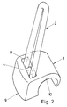
- FIG 2 is a perspective view of a cable clip 8 which is preferably made of a plastics material and which is intended to be fastened to the support surface with the aid of a V-shaped fastener 2.
- the clip includes an attachment part 9 which has an essentially flat undersurface for abutment with the support surface, and also an arm 10 which extends from the attachment part 9 and which is intended to grip around a cable or the like to be attached to the support surface.
- the fastener 2 is placed in a rectangular, through-passing hole 11 which has located centrally therein a trapezium shaped part 4 which is arranged in the manner illustrated in Figure 1, such that the upper surface of said part is located beneath the upper surface of the attachment part 9 to such an extent that when the fastener means 2 is brought into abutment with the upper surface of the part 4 as the fastener means is driven into the support surface, the upper edge of the faster 4 will lie parallel with the upper surface of the attachment part 9.
- These cable clips are suited for use with any kind of fastener applicator or nail driving pistol, the clips, in this case, preferably being produced in a long, continuous strip.
- the fastener means are placed in respective clips prior to inserting the clips into the pistol-magazine, or alternatively the fastener means can be placed in a separate magazine and inserted in the clips in conjunction with firing the clips from the applicator or pistol.
- FIG 3 is a plan view and Figure 5 a side view, partly in section, of an embodiment of the invention comprising a suspension device 12 which includes a circular attachment part 13 having a centrally located circular hole 14, in which a hub 15 in the shape of a truncated cone is arranged with the base surface of the cone in plane with the surface of the attachment part 13 intended for abutment with the support surface and connected to the defining wall of the hole by means of three spokes 16, and which further includes an arm 17 which extends from the attachment part 13 and which is also intended for abutment with the support surface, the end part of the arm 17 merging with a hook 18.
- a suspension device 12 which includes a circular attachment part 13 having a centrally located circular hole 14, in which a hub 15 in the shape of a truncated cone is arranged with the base surface of the cone in plane with the surface of the attachment part 13 intended for abutment with the support surface and connected to the defining wall of the hole by means of three spokes 16, and which further includes an arm 17
- Figure 5 illustrates the suspension device 12 in co-action with a fastener means 19 which comprises a base part 20 having extending therefrom three legs 21 which are placed in the openings located between respective spokes 16 when fastening the suspension device 12 to a support surface 3.
- a fastener means 19 which comprises a base part 20 having extending therefrom three legs 21 which are placed in the openings located between respective spokes 16 when fastening the suspension device 12 to a support surface 3.
- the fastener legs 21 are driven into the support surface 3, the legs are caused to diverge within the confines of the support surface, such as to create crushed zones on mutually opposing sides of the legs 21, in the manner aforedescribed.
- Figure 4 is a bottom plan view of the fastener means 19, separate from the attachment device. The fastener means concerned is punched from sheet steel and the fastener legs are then bent while simultaneously cold working or bossing the device.
- the fastening reliability of the described suspension device and attachment device, and the method applied therewith is greatly superior to the fastening reliability of conventional methods and devices when the length of the fastener means is at least 2 ⁇ 5, preferably 3 ⁇ 5 - 4 times the height of the trapezium-shaped part, and when the angle defined by the fastener legs with the symmetry line of the attachment device is greater than 8°, and if possible at least 11°.
- the length of the fastener means in relation to that part of the device which causes the device to expand in the support surface, and also the extent of such divergence, can be varied within relatively wide limits without departing from the scope of the invention.
Landscapes
- General Engineering & Computer Science (AREA)
- Engineering & Computer Science (AREA)
- Mechanical Engineering (AREA)
- Connection Of Plates (AREA)
- Clamps And Clips (AREA)
- Hooks, Suction Cups, And Attachment By Adhesive Means (AREA)
- Supports Or Holders For Household Use (AREA)
- Dental Tools And Instruments Or Auxiliary Dental Instruments (AREA)
- Measurement Of The Respiration, Hearing Ability, Form, And Blood Characteristics Of Living Organisms (AREA)
- Automobile Manufacture Line, Endless Track Vehicle, Trailer (AREA)
- Investigating Strength Of Materials By Application Of Mechanical Stress (AREA)
- Slide Fasteners, Snap Fasteners, And Hook Fasteners (AREA)
- Polishing Bodies And Polishing Tools (AREA)
Abstract
Claims (2)
Priority Applications (1)
| Application Number | Priority Date | Filing Date | Title |
|---|---|---|---|
| AT87906017T ATE65587T1 (de) | 1986-09-12 | 1987-08-31 | Verfahren zur befestigung einer befestigungsoder aufhaengeanordnung und vorrichtung zu dessen durchfuehrung. |
Applications Claiming Priority (2)
| Application Number | Priority Date | Filing Date | Title |
|---|---|---|---|
| SE8603847 | 1986-09-12 | ||
| SE8603847A SE454290B (sv) | 1986-09-12 | 1986-09-12 | Forfarande for fastsettning av fest- eller upphengningsdon jemte don for forfarandets genomforande forfarande for fastsettning av fest- eller upphengningsdon jemte don for forfarandets genomforande |
Publications (2)
| Publication Number | Publication Date |
|---|---|
| EP0282536A1 EP0282536A1 (fr) | 1988-09-21 |
| EP0282536B1 true EP0282536B1 (fr) | 1991-07-24 |
Family
ID=20365571
Family Applications (1)
| Application Number | Title | Priority Date | Filing Date |
|---|---|---|---|
| EP87906017A Expired - Lifetime EP0282536B1 (fr) | 1986-09-12 | 1987-08-31 | Procede d'ancrage d'un dispositif de fixation ou de suspension et dispositif de realisation dudit procede |
Country Status (10)
| Country | Link |
|---|---|
| US (1) | US4988249A (fr) |
| EP (1) | EP0282536B1 (fr) |
| JP (1) | JP2545428B2 (fr) |
| AU (1) | AU598591B2 (fr) |
| DK (1) | DK160635C (fr) |
| ES (1) | ES2005316A6 (fr) |
| FI (1) | FI85754C (fr) |
| NO (1) | NO170505C (fr) |
| SE (1) | SE454290B (fr) |
| WO (1) | WO1988002072A1 (fr) |
Families Citing this family (9)
| Publication number | Priority date | Publication date | Assignee | Title |
|---|---|---|---|---|
| ATE237265T1 (de) | 1995-08-29 | 2003-05-15 | Philippe Holder | Stützelement und vorrichtung zum aufhängen und positionieren von gemälden oder dergleichen |
| FR2750463B1 (fr) * | 1996-03-19 | 2000-01-21 | Holder Philippe | Systeme de fixation d'objets sur des murs en materiaux tendres |
| US5695159A (en) * | 1995-12-04 | 1997-12-09 | Adams Mfg. Corp. | Removable fastener |
| JP4028018B2 (ja) * | 1996-03-29 | 2007-12-26 | 有限会社タカタデザインラボ | 物品固定具 |
| JP3425387B2 (ja) | 1999-03-29 | 2003-07-14 | 有限会社タカタデザインラボ | 物品の固定具 |
| GB0020907D0 (en) * | 2000-08-25 | 2000-10-11 | Henrob Ltd | Self-piercing rivet |
| JP5372192B2 (ja) * | 2011-06-18 | 2013-12-18 | 須藤 二三男 | 板状ピンを用いた壁装着具 |
| KR101265966B1 (ko) * | 2011-10-18 | 2013-05-22 | 주식회사 성우하이텍 | 셀프 피어싱 리벳 |
| JP6182415B2 (ja) * | 2012-10-04 | 2017-08-16 | 二三男 須藤 | 針部材を用いた壁装着具 |
Family Cites Families (13)
| Publication number | Priority date | Publication date | Assignee | Title |
|---|---|---|---|---|
| CA640865A (en) * | 1962-05-08 | J. Decaro Charles | Rivet | |
| US170740A (en) * | 1875-12-07 | Improvement in brackets for curtain-rollers | ||
| FR565144A (fr) * | 1923-04-16 | 1924-01-19 | Dispositifs empêchant le desserrage des vis, écrous, boulons ou organes analogues | |
| DE1077284B (de) * | 1954-01-15 | 1960-03-10 | Karst Fa Robert | Schelle aus elastischem Kunststoff zur Befestigung elektrischer Leitungen auf Waenden |
| US2901200A (en) * | 1956-04-23 | 1959-08-25 | Orville A Voeks | Electric cable staple |
| US3298651A (en) * | 1966-03-07 | 1967-01-17 | La Roy B Passer | Wall hanger |
| BE759644A (nl) * | 1970-11-10 | 1971-04-30 | Stenman Holland Nv | Bevestiging van een van tenminste een bevestigingsgat voorzien beslagdeel op een ondergrond |
| JPS521362A (en) * | 1975-06-24 | 1977-01-07 | Michiharu Nakayama | Forked nail |
| JPS606651Y2 (ja) * | 1976-08-27 | 1985-03-04 | 大成建設株式会社 | 既存コンクリ−ト構造物と新設コンクリート部との接合装置 |
| DE3115914A1 (de) * | 1981-04-22 | 1982-11-11 | Karl-Wilhelm Dipl.-Ing. 5883 Kierspe Sessinghaus | Befestigungselement fuer leitungen |
| DE3217617C2 (de) * | 1981-05-16 | 1985-09-12 | Fritz 5880 Lüdenscheid Bindenberger | Halter für Leichtbauplatten |
| JPS58177613U (ja) * | 1982-05-22 | 1983-11-28 | 株式会社大築 | 気泡軽量コンクリ−ト用止釘 |
| SE8400674D0 (sv) * | 1984-02-09 | 1984-02-09 | Christer Forsgren | Clips, feste for ror, kablar etc i porosa material som t ex gipsplattor |
-
1986
- 1986-09-12 SE SE8603847A patent/SE454290B/sv not_active IP Right Cessation
-
1987
- 1987-08-31 AU AU79147/87A patent/AU598591B2/en not_active Ceased
- 1987-08-31 US US07/187,450 patent/US4988249A/en not_active Expired - Lifetime
- 1987-08-31 EP EP87906017A patent/EP0282536B1/fr not_active Expired - Lifetime
- 1987-08-31 JP JP62505383A patent/JP2545428B2/ja not_active Expired - Lifetime
- 1987-08-31 WO PCT/SE1987/000388 patent/WO1988002072A1/fr active IP Right Grant
- 1987-09-11 ES ES8702628A patent/ES2005316A6/es not_active Expired
-
1988
- 1988-04-20 NO NO881711A patent/NO170505C/no unknown
- 1988-04-29 FI FI882022A patent/FI85754C/sv not_active IP Right Cessation
- 1988-05-11 DK DK261588A patent/DK160635C/da not_active IP Right Cessation
Also Published As
| Publication number | Publication date |
|---|---|
| US4988249A (en) | 1991-01-29 |
| DK261588A (da) | 1988-05-11 |
| FI85754B (fi) | 1992-02-14 |
| NO170505B (no) | 1992-07-13 |
| NO881711L (no) | 1988-04-20 |
| SE8603847D0 (sv) | 1986-09-12 |
| AU598591B2 (en) | 1990-06-28 |
| FI882022A0 (fi) | 1988-04-29 |
| EP0282536A1 (fr) | 1988-09-21 |
| JPH01501164A (ja) | 1989-04-20 |
| FI882022A (fi) | 1988-04-29 |
| JP2545428B2 (ja) | 1996-10-16 |
| FI85754C (sv) | 1992-05-25 |
| NO170505C (no) | 1992-10-21 |
| NO881711D0 (no) | 1988-04-20 |
| SE454290B (sv) | 1988-04-18 |
| SE8603847L (fr) | 1988-03-13 |
| DK160635C (da) | 1991-09-16 |
| DK160635B (da) | 1991-04-02 |
| WO1988002072A1 (fr) | 1988-03-24 |
| DK261588D0 (da) | 1988-05-11 |
| AU7914787A (en) | 1988-04-07 |
| ES2005316A6 (es) | 1989-03-01 |
Similar Documents
| Publication | Publication Date | Title |
|---|---|---|
| JPH044616Y2 (fr) | ||
| US4565041A (en) | Movable partition base attachment | |
| US4435938A (en) | Vinyl siding attachment | |
| US4728237A (en) | Drivable picture frame hanger | |
| US4432182A (en) | Ceiling tile suspension system | |
| US3438664A (en) | Structural assembly and clip | |
| US5410854A (en) | Connector brackets | |
| US20120056051A1 (en) | Fastener assembly | |
| JP6133441B2 (ja) | 外周トリム用クリップ | |
| US3298646A (en) | Beam flange clamp | |
| EP0282536B1 (fr) | Procede d'ancrage d'un dispositif de fixation ou de suspension et dispositif de realisation dudit procede | |
| US4106251A (en) | Relocatable wall mounting system | |
| US4338755A (en) | Fastener assembly | |
| US3753324A (en) | Metal stud assembly | |
| US4337915A (en) | Brick clip-on hanger | |
| CA1225223A (fr) | Agrafe en fil metallique pour l'assemblage de panneaux de gypse | |
| JPH10502840A (ja) | 締付け器具 | |
| WO1999066143A1 (fr) | Fixation d'elements de construction | |
| US3991963A (en) | Curtain rod support | |
| WO1985003560A1 (fr) | Attaches, bride pour tuyaux, cables, etc., dans des materiaux poreux par exemple un panneau en platre | |
| JP3385323B2 (ja) | 天井吊り金物 | |
| JPH0870984A (ja) | 吊り下げ用フック | |
| US4616461A (en) | Wall panel attachment hook | |
| KR102132227B1 (ko) | 벽 부착용 행거 | |
| JP2764040B2 (ja) | 軟弱ボード用物品固定具 |
Legal Events
| Date | Code | Title | Description |
|---|---|---|---|
| PUAI | Public reference made under article 153(3) epc to a published international application that has entered the european phase |
Free format text: ORIGINAL CODE: 0009012 |
|
| 17P | Request for examination filed |
Effective date: 19880428 |
|
| AK | Designated contracting states |
Kind code of ref document: A1 Designated state(s): AT BE CH DE FR GB IT LI LU NL SE |
|
| 17Q | First examination report despatched |
Effective date: 19890216 |
|
| GRAA | (expected) grant |
Free format text: ORIGINAL CODE: 0009210 |
|
| AK | Designated contracting states |
Kind code of ref document: B1 Designated state(s): AT BE CH DE FR GB IT LI LU NL SE |
|
| PG25 | Lapsed in a contracting state [announced via postgrant information from national office to epo] |
Ref country code: SE Effective date: 19910724 |
|
| REF | Corresponds to: |
Ref document number: 65587 Country of ref document: AT Date of ref document: 19910815 Kind code of ref document: T |
|
| ITF | It: translation for a ep patent filed | ||
| ET | Fr: translation filed | ||
| REF | Corresponds to: |
Ref document number: 3771704 Country of ref document: DE Date of ref document: 19910829 |
|
| PG25 | Lapsed in a contracting state [announced via postgrant information from national office to epo] |
Ref country code: LU Free format text: LAPSE BECAUSE OF NON-PAYMENT OF DUE FEES Effective date: 19910831 |
|
| PLBE | No opposition filed within time limit |
Free format text: ORIGINAL CODE: 0009261 |
|
| STAA | Information on the status of an ep patent application or granted ep patent |
Free format text: STATUS: NO OPPOSITION FILED WITHIN TIME LIMIT |
|
| 26N | No opposition filed | ||
| PGFP | Annual fee paid to national office [announced via postgrant information from national office to epo] |
Ref country code: FR Payment date: 19960809 Year of fee payment: 10 |
|
| PGFP | Annual fee paid to national office [announced via postgrant information from national office to epo] |
Ref country code: AT Payment date: 19960813 Year of fee payment: 10 |
|
| PGFP | Annual fee paid to national office [announced via postgrant information from national office to epo] |
Ref country code: BE Payment date: 19961009 Year of fee payment: 10 |
|
| PG25 | Lapsed in a contracting state [announced via postgrant information from national office to epo] |
Ref country code: BE Free format text: LAPSE BECAUSE OF NON-PAYMENT OF DUE FEES Effective date: 19970831 Ref country code: AT Free format text: LAPSE BECAUSE OF NON-PAYMENT OF DUE FEES Effective date: 19970831 |
|
| BERE | Be: lapsed |
Owner name: THORSMAN & CO A.B. Effective date: 19970831 |
|
| PG25 | Lapsed in a contracting state [announced via postgrant information from national office to epo] |
Ref country code: FR Free format text: LAPSE BECAUSE OF NON-PAYMENT OF DUE FEES Effective date: 19980430 |
|
| REG | Reference to a national code |
Ref country code: FR Ref legal event code: ST |
|
| PGFP | Annual fee paid to national office [announced via postgrant information from national office to epo] |
Ref country code: GB Payment date: 19990825 Year of fee payment: 13 |
|
| PGFP | Annual fee paid to national office [announced via postgrant information from national office to epo] |
Ref country code: NL Payment date: 19990830 Year of fee payment: 13 |
|
| PGFP | Annual fee paid to national office [announced via postgrant information from national office to epo] |
Ref country code: DE Payment date: 19990906 Year of fee payment: 13 |
|
| PGFP | Annual fee paid to national office [announced via postgrant information from national office to epo] |
Ref country code: CH Payment date: 20000131 Year of fee payment: 13 |
|
| PG25 | Lapsed in a contracting state [announced via postgrant information from national office to epo] |
Ref country code: LI Free format text: LAPSE BECAUSE OF NON-PAYMENT OF DUE FEES Effective date: 20000831 Ref country code: GB Free format text: LAPSE BECAUSE OF NON-PAYMENT OF DUE FEES Effective date: 20000831 Ref country code: CH Free format text: LAPSE BECAUSE OF NON-PAYMENT OF DUE FEES Effective date: 20000831 |
|
| PG25 | Lapsed in a contracting state [announced via postgrant information from national office to epo] |
Ref country code: NL Free format text: LAPSE BECAUSE OF NON-PAYMENT OF DUE FEES Effective date: 20010301 |
|
| REG | Reference to a national code |
Ref country code: CH Ref legal event code: PL |
|
| GBPC | Gb: european patent ceased through non-payment of renewal fee |
Effective date: 20000831 |
|
| NLV4 | Nl: lapsed or anulled due to non-payment of the annual fee |
Effective date: 20010301 |
|
| PG25 | Lapsed in a contracting state [announced via postgrant information from national office to epo] |
Ref country code: DE Free format text: LAPSE BECAUSE OF NON-PAYMENT OF DUE FEES Effective date: 20010501 |
|
| PG25 | Lapsed in a contracting state [announced via postgrant information from national office to epo] |
Ref country code: IT Free format text: LAPSE BECAUSE OF NON-PAYMENT OF DUE FEES;WARNING: LAPSES OF ITALIAN PATENTS WITH EFFECTIVE DATE BEFORE 2007 MAY HAVE OCCURRED AT ANY TIME BEFORE 2007. THE CORRECT EFFECTIVE DATE MAY BE DIFFERENT FROM THE ONE RECORDED. Effective date: 20050831 |