EP0280901A2 - Pompe à piston plongeur - Google Patents
Pompe à piston plongeur Download PDFInfo
- Publication number
- EP0280901A2 EP0280901A2 EP88101593A EP88101593A EP0280901A2 EP 0280901 A2 EP0280901 A2 EP 0280901A2 EP 88101593 A EP88101593 A EP 88101593A EP 88101593 A EP88101593 A EP 88101593A EP 0280901 A2 EP0280901 A2 EP 0280901A2
- Authority
- EP
- European Patent Office
- Prior art keywords
- plunger
- pump
- work
- plungers
- pressure
- Prior art date
- Legal status (The legal status is an assumption and is not a legal conclusion. Google has not performed a legal analysis and makes no representation as to the accuracy of the status listed.)
- Granted
Links
Images
Classifications
-
- F—MECHANICAL ENGINEERING; LIGHTING; HEATING; WEAPONS; BLASTING
- F04—POSITIVE - DISPLACEMENT MACHINES FOR LIQUIDS; PUMPS FOR LIQUIDS OR ELASTIC FLUIDS
- F04B—POSITIVE-DISPLACEMENT MACHINES FOR LIQUIDS; PUMPS
- F04B1/00—Multi-cylinder machines or pumps characterised by number or arrangement of cylinders
- F04B1/02—Multi-cylinder machines or pumps characterised by number or arrangement of cylinders having two cylinders
-
- F—MECHANICAL ENGINEERING; LIGHTING; HEATING; WEAPONS; BLASTING
- F04—POSITIVE - DISPLACEMENT MACHINES FOR LIQUIDS; PUMPS FOR LIQUIDS OR ELASTIC FLUIDS
- F04B—POSITIVE-DISPLACEMENT MACHINES FOR LIQUIDS; PUMPS
- F04B49/00—Control, e.g. of pump delivery, or pump pressure of, or safety measures for, machines, pumps, or pumping installations, not otherwise provided for, or of interest apart from, groups F04B1/00 - F04B47/00
- F04B49/22—Control, e.g. of pump delivery, or pump pressure of, or safety measures for, machines, pumps, or pumping installations, not otherwise provided for, or of interest apart from, groups F04B1/00 - F04B47/00 by means of valves
- F04B49/24—Bypassing
- F04B49/243—Bypassing by keeping open the inlet valve
Definitions
- the invention relates to a plunger pump with at least two plunger work spaces and the same associated, in-phase working plungers or plunger parts, which displace different or equal amounts of the pump medium in their in-phase strokes, and with a triggerable suction valve, which the working space of the larger volume displacing a plunger or Is assigned to the plunger part and, when triggered, remains permanently in the open position, so that when the suction valve is triggered by means of the other plunger or plunger part displacing the smaller volume, a low flow rate with high pressure and when the suction valve is working by means of the work of both plunger or plunger parts large flow with low pressure with unchanged power requirement of the pump allowed to generate.
- Conventional plunger pumps switchable between high and low pressure typically have plungers with two sections of different cross sections, such that a relatively large annular step is formed between the section with the larger cross section and the section with the smaller cross section.
- the section with the smaller cross section arranged as the free end of the plunger works in a first Plunger work space, while the area with the ring step works in a second work space that is sealed off from the first work space.
- Each work area has separate suction and pressure valves, the suction valve of the work area accommodating the ring step portion of the plunger being releasable, so that this pump part is ineffective when the suction valve is triggered and is therefore permanently open. In this case, only the pump part formed by the working space for the free plunger end with the small cross section works.
- the pressure valve of the working area accommodating the ring stage area of the plunger is usually only designed for relatively low pressures, an additional changeover valve arrangement must be present which is triggered during high pressure operation of the pump, ie when the suction valve of the working area accommodating the ring step area of the plunger is activated and thus continuously is open, the pressure valve of this working space shields against the pressure of the flow emerging from the other working space.
- a plunger pump of the type specified above in that the two plunger working spaces are connected to one another by a line with a check valve closing in the direction of the working space of one plunger or plunger part, with the suction side of the pump only via the triggerable suction valve of the working space of one plunger or plunger part and are connected to the pressure side of the pump only via a pressure valve assigned to the plunger work space of the other plunger or plunger part.
- the working spaces of the two different volume-displacing plungers or plunger parts are connected in series, ie the flow rate of the pump passes through both working spaces of the two plungers or plunger parts in each case. Because of this arrangement, only three valves are necessary for the two workrooms.
- the check valve arranged in the line between the plunger work spaces, when the suction valve is triggered, works in the usual way as a suction valve of the plunger work space with the plunger or plunger part displacing the smaller volume, while the work of the other plunger or plunger part remains ineffective due to the triggered suction valve and the pump accordingly only works effectively with the other plunger or plunger part.
- switchover valve arrangements on the pressure side of the pump are also unnecessary. Because due to the series connection of the working spaces, the entire delivery flow generated by the pump emerges at the pressure valve of the working space, which is assigned to the plunger or plunger part displacing the smaller volume. It is therefore unnecessary to summarize the flow rates of the two work spaces by separate measures or to protect a pressure valve of a work space serving to generate a flow rate at low pressure from the high pressure which may be generated.
- the two different volume-displacing plungers or plunger parts are arranged in mutually parallel working spaces, which are arranged in an axial view of a crank engine driving the plungers when the plungers are arranged one above the other or when the plungers are arranged standing next to one another are.
- the two plungers or plunger parts by means of a common crosshead or slide with a common, with the crosshead or slide through connecting rod or the like. drive-connected crank crankshaft crank drive are coupled.
- This design is characterized by its particular compactness.
- the crankshaft can be dimensioned relatively short.
- the two working spaces of the plunger or plunger parts can easily be accommodated in a block whose height or width is less than the height or width of the crankcase.
- this design is characterized in that largely conventional parts can be used for crank mechanisms, crossheads and plungers.
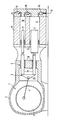
- the pump shown has a crank mechanism 1 with a crankcase 2, a crankshaft 3, connecting rods 4 and crossheads 5, which are displaceably arranged in piston-like manner in crosshead guides 6 and carry out lifting movements in a known manner when the crankshaft 3 rotates.
- Each crosshead 5 is connected to two plungers 7 and 8, which are arranged within associated plunger work spaces 9 and 10, which in turn are arranged as parts of a cylinder block 11 connected to the crankcase 2.
- the plungers 7 and 8 are guided in a known manner in sealing arrangements 12 at the ends of the plunger work spaces 9 and 10 on the crosshead side in order to seal the plunger work spaces 9 and 10 towards the crossheads 5.
- the upper plunger 8 in the figure has a smaller cross section than the lower plunger 7. Accordingly, the plungers 7 and 8 displace different amounts of media during their strokes.
- valve block 13 On the side facing away from the cross heads 5, the cylinder block 11 is connected to a valve block 13 which has a total of three valves for the two plunger work spaces 9 and 10, namely a suction valve connecting the plunger work space 9 with the suction side or a suction line of the pump, not shown 14, a check valve 15 arranged between the plunger work spaces 9 and 10 and allowing only a flow in the direction of the plunger work space 10, and a pressure valve 16 leading from the plunger work space 10 to the pressure side or a pressure line (not shown) of the pump.
- the valves 14 to 16 are schematized as ball valves shown, in principle, however, other valve constructions are possible and generally also useful.
- the suction valve 14 is designed to be releasable, ie the valve body of the suction valve 14 can be kept permanently in the open position by means of a tappet 17. Additional valves are not required for plunger work rooms 9 and 10.
- the plunger working spaces 9 and 10 fill with pump medium which flows in through the valves 14 and 15 opening in the suction stroke, the suction valve 14 being different from the sum of the Plunger work rooms 9 and 10 penetrating currents and the check valve 15 are only penetrated by the current flowing into the plunger work room 10.
- the pressure valve 16 remains closed, because in the plunger work space 10 there is only the pressure on the suction side of the pump which is reduced compared to the pressure side of the pump or a pressure slightly below it.
- the suction valve 14 closes, while the check valve 15 remains open or is again brought into the open position together with the now opening pressure valve 16 because the plunger 7 is now medium displace medium from the plunger work space 10 from the plunger work space 9 and the plunger 8. Accordingly, the check valve 15 is traversed by the medium flowing out of the plunger work space 9, while the pressure valve 16 flows through the sum of the quantities of the pump medium emerging from the plunger work spaces 9 and 10.
- the mode of operation described above is low-pressure operation because the pump works with both plungers 7 and 8 and thus with a relatively large plunger cross section. If the pump is to operate in high pressure mode, the suction valve 14 is triggered by corresponding actuation of the tappet 17 and is thus kept in the open position continuously. Accordingly, the plunger 7 cannot perform any pumping work; rather, the medium sucked in by it in the suction stroke during the pressure stroke is conveyed back through the suction valve 14 to the suction side of the pump. Only the plunger 8 can perform effective pumping work, because the check valve 15 now works in the manner of a conventional suction valve, i.e.
- the check valve 15 opens in the suction stroke of the plunger 8 and closes on its pressure stroke, since in the plunger work space 9, due to the continuously open suction valve 14, only a reduced pressure compared to the pressure in the plunger work space 10 can be present, approximately corresponding to the suction-side pressure of the pump.
- the pressure valve 16 opens during the pressure stroke of the plunger 8 under the influence of the medium displaced by the plunger 8. Since in this phase the pump can only perform effective pumping work with the plunger 8 and works with a relatively small plunger cross section, very high pressures can be generated without increasing the power of a drive unit which drives the crankshaft 3.
- a special feature of the pump shown is that the plunger work rooms 9 and 10 are connected in series, i.e. the entire medium conveyed by the plungers 7 and 8 to the pressure side passes through the plunger work rooms 9 and 10 in succession.
- the plunger work rooms 9 and 10 are connected in series, i.e. the entire medium conveyed by the plungers 7 and 8 to the pressure side passes through the plunger work rooms 9 and 10 in succession.
- the cross head 5 which is only shown schematically, consists essentially of two rod parts 18 with a circular cross section, which are arranged coaxially with the plungers 7 and 8, the rod parts 18 possibly being hollow to reduce weight.
- the rod parts 18 are separately slidably mounted in guide bushings 19, which are arranged in suitable cylinder bores of the crankcase 2.
- the rod parts 18 are connected in the longitudinal direction by means of a yoke 20 without being displaceable relative to one another.
- the yoke 20 is in turn articulated to the connecting rod 4.
- the ends of the rod parts 18 facing away from the yoke 20 are releasably connected in a generally known manner to the plungers 7 and 8 as in conventional pumps, the plungers 7 and 8 being able to have a limited angular mobility, in particular relative to the rod parts 18, so that assembly tolerances in the Alignment of crankcase 2 and cylinder block 11 are unproblematic.
- the invention is not restricted to plunger pumps in the narrower sense. Instead of the plungers shown, other displacement arrangements can also be provided. In principle, this does not change the arrangement of the valves 14 to 16.
- both plungers 7 and 8 with the same cross-sections and to achieve the different displaced quantities per stroke in that the plungers carry out strokes of different sizes, for example by driving-coupled plungers with differently dimensioned crankshaft crankshafts .
- valves 14 to 16 can also be arranged in a corresponding manner in the known pump described at the outset, so that the working space receiving the annular step region of the plunger is connected in series to the other working space, which takes up the free plunger end with a smaller cross section.
- a pump construction is generally less useful because of the large dimension in the longitudinal direction of the plunger.
- a plunger seal must be arranged between the two plunger work spaces and is therefore only loaded by very slight pressure differences when the pump is operated at low pressure when the stepped plunger works effectively in both work spaces, in particular in the pressure stroke. Such is undesirable with regard to a good sealing effect, as is required above all in high-pressure operation, when the plunger does effective pumping work only with its free end, which has a small cross section.
- the pump according to the invention can optionally also be used advantageously as a control pump. Depending on whether the suction valve 14 is triggered or not, the pump then works effectively with both plungers 7 and 8 or only with the plunger 8.
- the pump can work in both operating states of the suction valve on the pressure side against a constant pressure, so that the pump depending on the effective plunger cross section (when the suction valve 14 is triggered, the cross section of the plunger 8; when the suction valve 14 is not triggered, the sum of the cross sections of the plungers 7 and 8) operates with correspondingly different delivery rates and outputs.
- the pump according to the invention can optionally be converted to achieve a particularly large flow rate at a relatively low pressure.
- each pump can be modified to achieve a particularly large delivery rate at low pressure by arranging plungers with an enlarged cross-section, whereby the plunger work spaces must generally also be drilled out in order to be able to arrange the changed plungers.
- Such a modification of a pump is, however, only possible to a limited extent, because due to the incremental size specified by the crank engine, i.e. the distance between the plunger axes or crank cranks in the axial direction of the crankshaft, a maximum possible plunger diameter is specified.
- the diameter of the plunger 8 can be increased considerably, generally at least to the size of the plunger 7, ie the Cylinder block 11 allows the arrangement of a significantly larger plunger 8 and a work space 10 with a correspondingly enlarged cross section.
- a pump with an extraordinarily high throughput can be achieved, if necessary, whereby the triggering device 17 for the suction valve 14 and the check valve 15 between the plunger work spaces 9 and 10 can be dispensed with. All that is needed is a permanently open connection line between the plunger work rooms 9 and 10, which is arranged instead of the check valve 15.
- a one-piece crosshead with a large, possibly oval cross section can also be arranged and connected directly to the plungers 7 and 8 and the connecting rod 4. With such a construction, the yoke 20 is unnecessary.
Landscapes
- Engineering & Computer Science (AREA)
- Mechanical Engineering (AREA)
- General Engineering & Computer Science (AREA)
- Details Of Reciprocating Pumps (AREA)
- Reciprocating Pumps (AREA)
Applications Claiming Priority (2)
| Application Number | Priority Date | Filing Date | Title |
|---|---|---|---|
| DE19873706785 DE3706785A1 (de) | 1987-03-03 | 1987-03-03 | Plungerpumpe |
| DE3706785 | 1987-03-03 |
Publications (3)
| Publication Number | Publication Date |
|---|---|
| EP0280901A2 true EP0280901A2 (fr) | 1988-09-07 |
| EP0280901A3 EP0280901A3 (en) | 1988-12-21 |
| EP0280901B1 EP0280901B1 (fr) | 1990-02-07 |
Family
ID=6322168
Family Applications (1)
| Application Number | Title | Priority Date | Filing Date |
|---|---|---|---|
| EP88101593A Expired - Lifetime EP0280901B1 (fr) | 1987-03-03 | 1988-02-04 | Pompe à piston plongeur |
Country Status (4)
| Country | Link |
|---|---|
| EP (1) | EP0280901B1 (fr) |
| JP (1) | JPS63230967A (fr) |
| DE (2) | DE3706785A1 (fr) |
| ES (1) | ES2012506B3 (fr) |
Cited By (3)
| Publication number | Priority date | Publication date | Assignee | Title |
|---|---|---|---|---|
| WO2015071405A1 (fr) * | 2013-11-18 | 2015-05-21 | Robert Bosch Gmbh | Pompe d'injection de carburant |
| CN112594181A (zh) * | 2020-12-29 | 2021-04-02 | 北京恩萨工程技术有限公司 | 一种基于无抽吸作用的单柱塞泵闸板阀 |
| CN116641887A (zh) * | 2023-06-21 | 2023-08-25 | 山东科瑞油气装备有限公司 | 一种压裂泵液力端 |
Families Citing this family (3)
| Publication number | Priority date | Publication date | Assignee | Title |
|---|---|---|---|---|
| JP5972625B2 (ja) * | 2012-03-23 | 2016-08-17 | 住友重機械工業株式会社 | 流体圧増減圧機 |
| DE102012224308A1 (de) * | 2012-12-21 | 2014-06-26 | Continental Automotive Gmbh | Hochdruckpumpe |
| CN109826772B (zh) * | 2019-04-03 | 2024-05-28 | 四川轻化工大学 | 一种连续流动注射泵系统及其控制方法 |
Family Cites Families (8)
| Publication number | Priority date | Publication date | Assignee | Title |
|---|---|---|---|---|
| US1322236A (en) * | 1919-11-18 | oe modesto | ||
| AT8837B (de) * | 1900-12-10 | 1902-08-25 | Henry Turner | Luft- oder Flüssigkeitspumpe. |
| FR1180560A (fr) * | 1956-08-03 | 1959-06-05 | Dobson Ltd W E & F | Perfectionnements apportés aux pompes hydrauliques |
| US3311065A (en) * | 1964-10-15 | 1967-03-28 | Plastering Dev Ct Inc | Pumping apparatus |
| DD64353A1 (de) * | 1967-10-06 | 1968-10-20 | Manfred Thierfelder | Kolbenpumpe mit mehreren Druckstufen |
| US4245963A (en) * | 1979-02-09 | 1981-01-20 | Waters Associates, Inc. | Pump |
| JPH0437270Y2 (fr) * | 1984-12-05 | 1992-09-02 | ||
| JPH0442530Y2 (fr) * | 1985-02-25 | 1992-10-07 |
-
1987
- 1987-03-03 DE DE19873706785 patent/DE3706785A1/de not_active Withdrawn
-
1988
- 1988-02-04 DE DE8888101593T patent/DE3860037D1/de not_active Expired - Lifetime
- 1988-02-04 EP EP88101593A patent/EP0280901B1/fr not_active Expired - Lifetime
- 1988-02-04 ES ES88101593T patent/ES2012506B3/es not_active Expired - Lifetime
- 1988-03-02 JP JP63047687A patent/JPS63230967A/ja active Pending
Cited By (3)
| Publication number | Priority date | Publication date | Assignee | Title |
|---|---|---|---|---|
| WO2015071405A1 (fr) * | 2013-11-18 | 2015-05-21 | Robert Bosch Gmbh | Pompe d'injection de carburant |
| CN112594181A (zh) * | 2020-12-29 | 2021-04-02 | 北京恩萨工程技术有限公司 | 一种基于无抽吸作用的单柱塞泵闸板阀 |
| CN116641887A (zh) * | 2023-06-21 | 2023-08-25 | 山东科瑞油气装备有限公司 | 一种压裂泵液力端 |
Also Published As
| Publication number | Publication date |
|---|---|
| JPS63230967A (ja) | 1988-09-27 |
| EP0280901A3 (en) | 1988-12-21 |
| DE3860037D1 (en) | 1990-03-15 |
| EP0280901B1 (fr) | 1990-02-07 |
| DE3706785A1 (de) | 1988-09-15 |
| ES2012506B3 (es) | 1990-04-01 |
Similar Documents
| Publication | Publication Date | Title |
|---|---|---|
| EP0808422B1 (fr) | Procede et dispositif de transfert de beton ou d'autres liquides epais | |
| DE69220202T2 (de) | Doppelarbeitende hydraulische Vorrichtung zum Stanzen, Schneiden, Biegen usw. | |
| DE69505203T2 (de) | Hydraulischer Kreislauf | |
| DE2612800C2 (de) | Hydraulische Steuerventilanordnung für einen Behandlungstisch | |
| DE2503458A1 (de) | Kniehebelpresse | |
| EP0909883A1 (fr) | Dispositif et méthode de commande des soupapes de moteur diesel réversible | |
| DE3048776A1 (de) | Druckwandlergeraet | |
| DE2015472A1 (de) | Schubkolbenmotor | |
| DE69905300T2 (de) | Hydraulische Steuereinheit, insbesondere für die Bedienung von einem Klappdach eines Fahrzeugs | |
| EP0594103A1 (fr) | Machine de brochage interne, spécialement machine de brochage verticale | |
| EP0280901B1 (fr) | Pompe à piston plongeur | |
| DD209220A5 (de) | Stopfaggregat fuer eine fahrbare gleisbaumaschine | |
| DE1755697B2 (de) | Hydraulische Hilfskraftlenkeinrichtung für Kraftfahrzeuge | |
| DE1653406C3 (de) | Hydraulisches Gestänge in einer zweizylindrischen Betonpumpe | |
| DE3200531A1 (de) | Anordnung fuer die zufuhr eines kompressiblen antriebsmediums zu einem antrieb | |
| EP1526930A1 (fr) | Cylindre principal ou cylindre de compression d'une extrudeuse | |
| DE2527829A1 (de) | Automatischer operateur fuer automatische strassen | |
| DE3545446C2 (fr) | ||
| DE6803021U (de) | Vorrichtung felgesteuerung fuer einen hydraulischen motor | |
| DE9217574U1 (de) | Steuerungsanordnung für eine Mehrzylinder-Dickstoffpumpe | |
| DE8427144U1 (de) | Kolben- bzw. plungerpumpe | |
| DE172109C (fr) | ||
| DE3247290A1 (de) | Hydraulische pumpe | |
| DE834530C (de) | Hydraulischer Arbeitskolben | |
| DE200369C (fr) |
Legal Events
| Date | Code | Title | Description |
|---|---|---|---|
| PUAI | Public reference made under article 153(3) epc to a published international application that has entered the european phase |
Free format text: ORIGINAL CODE: 0009012 |
|
| AK | Designated contracting states |
Kind code of ref document: A2 Designated state(s): DE ES FR GB IT SE |
|
| PUAL | Search report despatched |
Free format text: ORIGINAL CODE: 0009013 |
|
| AK | Designated contracting states |
Kind code of ref document: A3 Designated state(s): DE ES FR GB IT SE |
|
| 17P | Request for examination filed |
Effective date: 19890107 |
|
| 17Q | First examination report despatched |
Effective date: 19890623 |
|
| ITF | It: translation for a ep patent filed | ||
| GRAA | (expected) grant |
Free format text: ORIGINAL CODE: 0009210 |
|
| AK | Designated contracting states |
Kind code of ref document: B1 Designated state(s): DE ES FR GB IT SE |
|
| REF | Corresponds to: |
Ref document number: 3860037 Country of ref document: DE Date of ref document: 19900315 |
|
| ET | Fr: translation filed | ||
| GBT | Gb: translation of ep patent filed (gb section 77(6)(a)/1977) | ||
| PLBE | No opposition filed within time limit |
Free format text: ORIGINAL CODE: 0009261 |
|
| STAA | Information on the status of an ep patent application or granted ep patent |
Free format text: STATUS: NO OPPOSITION FILED WITHIN TIME LIMIT |
|
| 26N | No opposition filed | ||
| ITTA | It: last paid annual fee | ||
| PGFP | Annual fee paid to national office [announced via postgrant information from national office to epo] |
Ref country code: DE Payment date: 19941212 Year of fee payment: 8 |
|
| PGFP | Annual fee paid to national office [announced via postgrant information from national office to epo] |
Ref country code: FR Payment date: 19950116 Year of fee payment: 8 |
|
| PGFP | Annual fee paid to national office [announced via postgrant information from national office to epo] |
Ref country code: GB Payment date: 19950119 Year of fee payment: 8 |
|
| EAL | Se: european patent in force in sweden |
Ref document number: 88101593.7 |
|
| PGFP | Annual fee paid to national office [announced via postgrant information from national office to epo] |
Ref country code: ES Payment date: 19950220 Year of fee payment: 8 |
|
| PGFP | Annual fee paid to national office [announced via postgrant information from national office to epo] |
Ref country code: SE Payment date: 19950222 Year of fee payment: 8 |
|
| PG25 | Lapsed in a contracting state [announced via postgrant information from national office to epo] |
Ref country code: GB Effective date: 19960204 |
|
| PG25 | Lapsed in a contracting state [announced via postgrant information from national office to epo] |
Ref country code: SE Effective date: 19960205 Ref country code: ES Free format text: LAPSE BECAUSE OF NON-PAYMENT OF DUE FEES Effective date: 19960205 |
|
| GBPC | Gb: european patent ceased through non-payment of renewal fee |
Effective date: 19960204 |
|
| PG25 | Lapsed in a contracting state [announced via postgrant information from national office to epo] |
Ref country code: FR Effective date: 19961031 |
|
| PG25 | Lapsed in a contracting state [announced via postgrant information from national office to epo] |
Ref country code: DE Effective date: 19961101 |
|
| REG | Reference to a national code |
Ref country code: FR Ref legal event code: ST |
|
| REG | Reference to a national code |
Ref country code: ES Ref legal event code: FD2A Effective date: 19990405 |
|
| PG25 | Lapsed in a contracting state [announced via postgrant information from national office to epo] |
Ref country code: IT Free format text: LAPSE BECAUSE OF NON-PAYMENT OF DUE FEES;WARNING: LAPSES OF ITALIAN PATENTS WITH EFFECTIVE DATE BEFORE 2007 MAY HAVE OCCURRED AT ANY TIME BEFORE 2007. THE CORRECT EFFECTIVE DATE MAY BE DIFFERENT FROM THE ONE RECORDED. Effective date: 20050204 |