EP0280204A2 - Procédé et appareil pour le formage d'un flanc à un corps creux en matière thermoplastique - Google Patents
Procédé et appareil pour le formage d'un flanc à un corps creux en matière thermoplastique Download PDFInfo
- Publication number
- EP0280204A2 EP0280204A2 EP88102414A EP88102414A EP0280204A2 EP 0280204 A2 EP0280204 A2 EP 0280204A2 EP 88102414 A EP88102414 A EP 88102414A EP 88102414 A EP88102414 A EP 88102414A EP 0280204 A2 EP0280204 A2 EP 0280204A2
- Authority
- EP
- European Patent Office
- Prior art keywords
- hollow body
- tool
- flange
- wall
- end section
- Prior art date
- Legal status (The legal status is an assumption and is not a legal conclusion. Google has not performed a legal analysis and makes no representation as to the accuracy of the status listed.)
- Granted
Links
Images

Classifications
-
- B—PERFORMING OPERATIONS; TRANSPORTING
- B29—WORKING OF PLASTICS; WORKING OF SUBSTANCES IN A PLASTIC STATE IN GENERAL
- B29C—SHAPING OR JOINING OF PLASTICS; SHAPING OF MATERIAL IN A PLASTIC STATE, NOT OTHERWISE PROVIDED FOR; AFTER-TREATMENT OF THE SHAPED PRODUCTS, e.g. REPAIRING
- B29C57/00—Shaping of tube ends, e.g. flanging, belling or closing; Apparatus therefor, e.g. collapsible mandrels
-
- B—PERFORMING OPERATIONS; TRANSPORTING
- B29—WORKING OF PLASTICS; WORKING OF SUBSTANCES IN A PLASTIC STATE IN GENERAL
- B29L—INDEXING SCHEME ASSOCIATED WITH SUBCLASS B29C, RELATING TO PARTICULAR ARTICLES
- B29L2031/00—Other particular articles
- B29L2031/712—Containers; Packaging elements or accessories, Packages
- B29L2031/7132—Bowls, Cups, Glasses
Definitions
- the invention relates to a method and a device for molding a flange onto a hollow body made of thermoplastic material, the essentially cylindrical wall of which delimits an opening at one end.
- the hollow body to be provided with the flange it can be, for. B. is a hollow, substantially cylindrical and bottomed can-shaped molding, wherein the flange to be attached has the function of a flange edge, which is used to attach a lid.
- the flange to be molded can be made using a variety of methods, one of which is that a preform, for example injection molded, having a generally cylindrical wall, bottom and opening at the other end, by stretching the Wall below the glass transition temperature of the material forming the preform is formed into an intermediate product, which is then pre-expanded at its open end and then, starting from this open, pre-expanded end, expanded at least over most of its longitudinal extent and then heat-set, whereupon the aforementioned flange or flanged edge is formed.
- a preform for example injection molded, having a generally cylindrical wall, bottom and opening at the other end, by stretching the Wall below the glass transition temperature of the material forming the preform is formed into an intermediate product, which is then pre-expanded at its open end and then, starting from this open, pre-expanded end, expanded at least over most of its longitudinal extent and then heat-set, whereupon the aforementioned flange or flanged edge is formed.
- a product is created in which at least the material forming the wall is oriented to improve its mechanical properties.
- the end product will in most cases be a mass-produced article which can be manufactured in large quantities, so that the process of the method and the device used for its implementation should be as simple and clear and therefore reliable as possible.
- the invention has for its object to design the method and apparatus of the type described in the introduction so that economical mass production is possible.
- the processing operations to be carried out should, if possible, be coordinated with one another in such a way that optimal use of the tools and other devices required for the treatment of the hollow bodies is possible.
- the individual work steps should take place and be coordinated with one another in such a way that the necessary shaping processes require as little temperature control processes and equipment as possible.
- the same also applies to the spatial arrangement of the tools required for the shaping processes.
- the largest diameter of the flange to be molded and also that of the cover that may be attached to it is not larger than the outside diameter of the cylindrical region of the hollow body.
- the invention proposes that the end portion of the wall delimiting the opening is heated and narrowed by external forces acting on it over the circumference of the end portion and then a circumferential flange is formed on this narrowed end section by a pressing process.
- the procedure is advantageously such that the narrowing of the end section takes place simultaneously with the heating thereof and as a function of the softening of the material forming the end section.
- the hollow body will generally be very thin-walled, especially if it is used as a can-shaped container, so that the forces acting on the hollow body must in any case be metered and distributed such that unwanted and in particular Irregular deformations such as wrinkling due to compression can be avoided in any case.
- the above-described procedure according to the invention has the advantage that a relatively small force is sufficient, which comes from the tool with an annular cross section to act on the end section of the wall of the hollow body in order to narrow this end section.
- the course of this deformation process takes place without positive control in such a way that the degree of softening of the end section to be narrowed determines the course for a given force acting on the tool. It is therefore possible to dispense with a forced drive of the tool, with certain fluctuations in the duration of the narrowing process possibly occurring from hollow body to hollow body, although these remain very small provided that the wall thickness of the section to be narrowed is subject to no or only slight fluctuations.
- the path to be covered by the tool during the narrowing e.g. B. is limited by a stop.
- the hollow body is under an internal overpressure during the work step causing the narrowing.
- This can be done by compressed air, which is expediently introduced into the hollow body through a channel located in the tool used for the narrowing.
- the second deformation step in which the flange is molded onto the narrowed end section of the hollow body, is advantageously carried out by utilizing the heat that was introduced into the latter in the course of the first work step to narrow the end section.
- this is possible if the individual work steps are coordinated so that there is only a short period of time between the end of the narrowing process and the pressing process for attaching the flange.
- This procedure is also favored by the fact that in the first step the temperature control, i.e. heating of the end section, is carried out by the first tool which is ring-shaped in cross section and remains in contact with the end section until the end of this presetting process and thus also heat until the end of the narrowing process transfers to the end portion of the hollow body.
- the narrow end portion of the hollow body can be brought into the area of a second tool which consists of a lower part with a recess, the inner contour of which is adapted to the shape of the flange to be molded on the hollow body, and a punch, the end region of which is in the recess of the lower part and the end section of the hollow body located therein, and the region of the stamp interacting with the hollow body wall is shaped in such a way that it initially widens the end section of the hollow body during insertion and, in the final phase of insertion, the circumferential flange between the lower part and the stamp is press-formed and the deformed area of the hollow body is cooled to such an extent that it receives sufficient dimensional stability.
- the pressing tool used for forming the flange can also serve to cool the deformed area of the wall. If necessary, at least one of the two pressing tools can be cooled, for example by a cooling liquid guided in a channel system arranged inside the pressing tool. Whether such special cooling is necessary or appropriate depends on the respective circumstances, e.g. B. on the wall thickness of the hollow body and thus on the amount of heat to be removed. . If the hollow body before the narrowing process, a heat set had been subjected to the operation in order to give it the thermal stability required for its future use, the narrowing of the end section of the hollow body and the subsequent compression molding of the flange should take place at a temperature which is above the heat setting temperature. The latter can be around 150 ° C. when using PETP, for example.
- the hollow body is under internal pressure during the compression molding of the flange. This is to prevent the wall of the hollow body from experiencing any other unwanted and controllable deformation under the action of the forces required for the compression molding.
- the use of such a support wall will generally depend on the thickness of the hollow body wall, since the rigidity of the latter increases with increasing wall thickness of the hollow body.
- the device for carrying out the above-described method is for narrowing the portion of the wall of the hollow body which delimits the opening with a End section to be guided, heated, cross-sectionally annular first tool, the inner diameter of which is at least as large as the outer diameter of the undeformed end section of the hollow body and decreases towards its side facing away from the hollow body on the end face facing the hollow body.
- this first tool can be closed on its side facing away from the hollow body and can be provided with a supply for compressed air.
- this first tool which is annular in cross section, can be approximately hood-shaped or bell-shaped, the interior of this hood or bell in the position interacting with the end portion of the hollow body to be narrowed constituting a continuation of the interior of the hollow body and the entire space the tool is closed at the top, so that an overpressure generated in the entire space is maintained by supplying compressed air.
- An embodiment has proven to be particularly advantageous in which the first tool, which is ring-shaped in cross section, is carried by the piston rod of a piston which is guided within a cylinder acted upon by compressed air.
- the action on the piston is chosen so that the resulting force acting in the direction of the hollow body is sufficient on the one hand to narrow the end section with sufficient heating and the resulting softening, but on the other hand does not cause any unacceptable deformations in the other, unheated areas of the hollow body .
- a second tool which consists of a lower part with a circular recess, the Limitation is adapted to the contour of the flange to be molded, and there is a stamp, the end area facing the hollow body is insertable into the recess of the lower part and the end section surrounding the lower part and is shaped so that it is adapted to the area of the lower part, which surrounds the narrowed end portion of the hollow body and the flange to be formed therefrom on the outside.
- the stamp is expediently provided with means for introducing compressed air into the hollow body. The excess pressure caused by the compressed air supports the inside of the wall of the hollow body.
- a sleeve arranged coaxially with the hollow body, the inner diameter of which is adapted to the outer diameter of the hollow body, and the sleeve is axially displaceable relative to the hollow body and can be brought into a position in which it covers the hollow body wall over at least the largest part their axial extent suitably surrounds so as to bring about an external support of the hollow body wall.
- the lower part of the tool for shaping the flange is advantageously divided for the purpose of demolding, whereby an annular locking element can be axially displaceably attached to the stamp, which in the course of the movement of the stamp in the direction of the lower part is brought into engagement with both parts of the lower part is before the lower part is subjected to forces by the stamp in the course of the shaping process.
- the sleeve serving for the external support of the hollow body can be brought into engagement in its effective position with the lower part of the tool, so as to bring about an additional locking which prevents the lower part from opening during the compression molding of the flange.
- the first tool which is annular in cross section, for narrowing the end section on the one hand and the second tool for forming the flange, on the other hand, in two treatment stations which are at a distance from one another, so that a hollow body can be treated in each of the treatment stations.
- the appropriate horizontal distance between the two stations should be as short as possible, so that the transport from the first station, in which the narrowing is carried out, to the second station, in which the flange is formed, takes up little time.
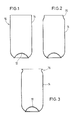
- each molding 10 consists essentially of an inwardly drawn, dome-shaped base 12 and a cylindrical wall 14, the upper, free end of which defines an opening.
- the molding 10 can be an intermediate product from a preform using one drawing and one closing expansion process have been produced, as described for example in FR-OS 25 67 066/85 10215.
- the wall of the molded article 10 has a thickness of, for example, 0.4 to 0.5 mm.
- the bottom 12 of the molding is noticeably thicker because it has not been influenced by the previous shaping processes, which have each led to a reduction in the thickness of the wall 14.
- the wall 14 of a molding 10 produced in the manner described above is oriented in the axial direction by the drawing process.
- the material forming the wall is oriented in the circumferential direction by the expansion process following the drawing process.
- the molding 10 by a stretch-blow process, as it is, for. B. is described in DE-AS 2 222 535.
- An orientation of the material forming the wall 14 is caused by an axial stretching process and the orientation of this material in the circumferential direction by the expansion process which is generally brought about by internal excess pressure.
- the molding shown in FIG. 1 is subjected to a molding process in two successive treatment steps.
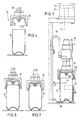
- the molded article 10 is first brought into a first treatment station 16, in which it is located below a first tool 15 and essentially axially aligned with it.
- This tool 15 is ring-shaped in cross section and closed on the upper side so that it has a bell-shaped or hood-shaped shape, the opening 17 of the hood or bell facing the molding 10.
- the inside diameter of the tool 15 takes from its opening 17 in the direction of its opposite, closed side such that the contour of the inner boundary of the wall 18 is adapted to the contour of the narrowed end section 20 to be produced on the molding 10.
- the tool 15 is carried by the piston rod 21 of a piston 22 which is guided within a pneumatic cylinder 24 and is pressurized on the molded article 10 in the direction of the latter during the molding of the narrowed end section 20. Furthermore, the interior of tool 15, which is open at the bottom, can be connected to a compressed air source. For this purpose, a channel 26 is provided for the supply of compressed air. The supply takes place via the hose line 38.
- the tool 15 consists essentially of an outer jacket 28 and an inner part 30 which is arranged coaxially to the jacket 28. (Fig. 5).
- a wire 32 is arranged between the two parts 28, 30 and serves as an electrical heating resistor for heating the inner part 30.
- the heating resistor 32 is connected to a voltage source via a line 36.
- the molding 10 brought into the first treatment station 16 by a transport slide 86 is aligned there to the tool 15 by the transport slide 86, a stop 88 and a fork 34 (FIG. 5).
- the first shaping step in which the upper end section 20 of the molding is narrowed, the latter is lowered onto the molding 10 from its initial position shown in FIG. 4.
- the inside diameter of the opening 17 of the tool 15 is slightly larger at its free end than the outside diameter of the essentially cylindrical molding 10.
- the tool 15 Since the tool 15 is heated via the wire 32, the contact between its inner wall 18 and the end section 20 of the wall 14 of the molding 10 leads to heat transfer, during which the thermoplastic material forming the end section 20 is softened. In this state, the end section 20 can be deformed using relatively low forces.
- the tool 15 is carried in the manner already described by the piston 22 which is guided within the pneumatic cylinder 24 and is acted upon in the direction of the molding 10 during the molding process.
- This arrangement has an automatic influence on the end section 20 of the molded article to be deformed and thus also on the subsequent, non-heated areas of the Wall 14 of the molding 10 acting forces, wherein the pressure acting on the piston can be easily adjusted so that the resulting forces are large enough to deform the softened end portion 20 of the molding 10, on the one hand, and on the other hand too small to prevent unwanted deformation of the molded article 10, in particular also in its non-heated area.
- the aforementioned action of the compressed air supplied through the duct 26 of the interior space enclosed by the molding 10 plays an important role, since it has a supporting function and in particular prevents the relatively slim molding 10 from buckling under the action of the pressure exerted by the tool 15.
- the inside of the end section 20 to be narrowed is acted on, so that during the shaping process in the course of the lowering movement of the tool 15 the end section 20 is under the action of outward forces which are evenly distributed over the circumference of the end section 20 and contribute to this to prevent the end portion 20 from being deformed irregularly, e.g. B. by formation of folds or the like.
- the outward forces caused by the internal overpressure are smaller than the inward forces transmitted through the inner wall 18 of the tool 15, but they are only fully effective where the inner wall 18 is in direct contact with the end section 20 of the molding 10.
- the tool 15 does not have a positive drive during its downward movement over the molding 10 for the purpose of deforming the end section 20 thereof, the path that the tool 15 travels in a suitable manner, e.g. B. limited by a stop. In this way it is ensured that the shape of the End section 20 in the first treatment step to the same extent is provided that the time required for this, which is essentially determined by the temperature of the tool 15 and the wall thickness of the end section 20, is available.
- the molding 10 has the shape shown in FIG. 2 of the drawing.
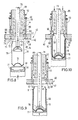
- the molding now provided with the narrowed section 20 is brought into the second treatment station 40 by a transport device (not shown in the drawing) (FIGS. 8-11).
- a two-part tool is arranged, which consists of a lower part 42 and a stamp 44 cooperating therewith.
- the lower part is plate-shaped and provided with a circular recess 45 (FIG. 11).
- the contour of the wall 46 delimiting this recess 45 corresponds to the final shape that the end section 20 is to receive in the second treatment station.
- the lower part 42 is divided into two halves 42a, 42b which can be displaced relative to one another in the horizontal plane.
- FIGS. 8 to 11 show the lower part 42 of the tool 42, 44 in its closed position.
- Both the lower part 42 and the punch 44 are provided with channels 48, 49 for the passage of a cooling medium.
- the stamp 44 is surrounded on the outside by an annular locking element 50 which is axially displaceable relative to the stamp 44 and by a coil spring 52 which is supported on the stamp 44 in a manner not shown, in the direction of the free end 54 of the stamp 44 is applied.
- a ring-shaped projection 56 is assigned to the annular locking element 50 and extends coaxially to the recess 45 on the upper side of the lower part 42.
- the end section 58 of the punch 44 is designed to taper conically towards its free end.
- This end section 58 is adjoined by a substantially cylindrical section 60, which at its end facing away from the free end 54 of the stamp 44 continues into a section 62 which is delimited in an arcuate manner in longitudinal section in such a way that it enlarges the outer diameter of the stamp in this section 62 has a course which corresponds to the desired course and the desired dimension of the flange to be molded on the hollow body.
- the arcuately delimited section 62 is delimited on its side facing away from the approximately cylindrical section 60 by a circumferential projection 66, the inner delimitation wall 68 of which abuts the section 62 approximately axially parallel to form an edge.
- the projection 66 cooperates with a circumferential groove 69, which is provided on the upper side of the lower part 42 of the tool coaxially to the recess 45.
- the wall 46 delimiting the recess 45 is essentially cylindrically delimited in its lower region.
- the diameter of the area 70 corresponds to the outer diameter of the wall 14 of the molding 10 in its area that remains undeformed.
- This essentially cylindrical region 70 is adjoined by a region 71 which tapers essentially conically in the direction of the plunger 44 and which corresponds to the transition between the portion of the wall 14 of the molding 10 which has remained undeformed and that after the treatment step has been carried out in the first treatment station 16 narrowest area of the end portion 20 of the Moldings 10 corresponds.
- This tapering area 71 is followed by a short, essentially cylindrically delimited area 72, the inside diameter of which is adapted to the outside diameter of the cylindrical section 60 of the stamp 44 such that an annular space remains between the two wall sections 72 on the one hand and 60 on the other hand the area of the wall 14 of the molding 10 located there is filled.
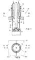
- a wall area 74 which has a larger diameter in longitudinal section in the direction of the punch 44, and is adapted in terms of its course and its dimension to the course and dimension of the section 62 to the punch 15, the wall area 74 of the lower part 42, on the one hand, and the wall area 62 of the plunger 44, on the other hand, run essentially parallel to one another and, in their effective end position according to FIG. 15, delimit an annular gap, the width of which in this area corresponds to the thickness of the portion 20 to be narrowed Flange 76 corresponds.
- the treatment station is assigned two holding means in the form of a bottom mandrel 77 and a holding mandrel 78, both of which can be displaced vertically independently of one another.
- the end faces of both the bottom mandrel 77 and the holding mandrel 78 are adapted to the shape of the bottom 12 of the molding 10.
- the holding mandrel 78 is carried by a rod 79 which axially in a longitudinal bore of the plunger 44 is movable.
- Both parts 78 and 79 are provided with a channel 89 for the supply of compressed air into the molding 10.
- the bottom mandrel 77 is coaxially surrounded by a support sleeve 90 which is vertically displaceable relative to the bottom mandrel 77.
- the bottom mandrel 77 and the holding mandrel 78 are each displaced in the direction of the bottom 12 of the molding 10 until both parts abut the bottom 12 and clamp it between them.
- the molding 10 is still in a position in which it is located below the lower part 42 of the tool. Due to the above-described clamping of the base 12 between the two holding means 77 and 78, the shape of the interacting parts also results in an axial alignment of the molding 10 with the tool.
- the support sleeve 90 After the base 12 has been clamped in, the support sleeve 90, the inside diameter of which is adapted to the outside diameter of the molded article 10, is shifted upwards to approximately the beginning of the narrowed region 20 (FIG. 9), which had been produced in the first treatment station 16. From this position, the two holding means 77, 78 and the support sleeve 90 are moved synchronously upward with the entrainment of the molding 10 until they have reached the position shown in FIG. 10 of the drawing. The lower part 42 of the tool is closed. In this position, it is locked from below by the support sleeve 90. For this purpose, an annular extension 91, which is conically delimited at least on one side, engages in a correspondingly delimited groove 92 of the lower part 42.
- the drawing shows that the contour of the tool 42 in the wall regions 70, 71 and 72 is adapted to the contour of the narrowed section 20 of the molding 10, so that the latter with its narrowed area 20 in the course of Upward movement of the parts 77, 78, 90 can be inserted into the recess 45 of the already closed lower part 42.
- the punch 44 When the molding 10 assumes the position shown in FIG. 10, the punch 44 is moved downward from its upper starting position shown in FIGS. 9, 10 and 13 into the recess 45 of the lower part 42 and into the opening of the molding 10 arranged coaxially therewith moved in.
- Fig. 13 of the drawing shows that the diameter of the free end 54 of the punch 44 is slightly smaller than the smallest diameter of the narrowed end portion 20 of the molding 10, so that the punch 44 first enters the opening of the molding 10 without the touch the wall bounding the opening. Possibly.
- the lower, conical end region 80 of the annular locking element 50 is brought into engagement with the projection 56 from the upper side of the lower part 42. Since the locking part 50 has reached its lower end position before the plunger 44 ends its downward movement, there is a relative displacement between the locking part 50 and the plunger 44, the helical spring 52, which is supported on the plunger 44 with its end facing away from the molding 10, being compressed.
- the locking element 50 and the extension 91 which also acts as a locking element
- the support sleeve has the task of locking the two halves 42a, 42b of the lower part 42 of the tool against one another in the closed position, so that the halves 42a, 42b remain closed during the subsequent pressing operations.
- the cylindrical section 60 of the plunger 44 then reaches the end section 20 of the molded article 10.
- the outer diameter of this cylindrical section 60 corresponds approximately to the smallest inner diameter of the narrowed area 20.
- compressed air is introduced into the interior of the molding 10 via the channel 89 in order to prevent the wall 14 of the molding 10 from buckling, in particular in the region 20 narrowed in the first treatment station 16, during the compression molding of the flange.
- Bulging of the molded article 10 to the outside is not possible, since its wall is supported on the outside by the support sleeve 90 which surrounds it from the outside (FIGS. 10 and 11).
- the internal overpressure in the molded article 10 also has the consequence that the portion of the region 20 which is not to be deformed to form the flange 76 is pressed against the wall of the lower part 42 and is cooled thereby.
- the lower end region of the projection 66 first enters the groove 69, as is shown in FIG. 15.
- the arrangement is such that the inner boundary wall 68 slides with little or no play on the inner boundary wall 82 of the groove 69 associated with the projection 66, so that the annular space 84 delimited by the two wall sections 62 on the punch 44 and 75 on the lower part 42 is closed on all sides, that is to say also to the outside, and a escape of thermoplastic material from the narrowed end section to the outside is prevented.
- the free edge of the narrowed section 20 is bent outwards to form a flange (FIG.
- a divergence of the material inwards in the direction of the undeformed wall area is likewise not possible or only to a negligible extent, since the annular gap between the cylindrical area 60 of the stamp 44 and the cylindrical area 72 of the lower part 42 is completely filled with material and because of it Small width has such a large flow resistance that evasion of material through this annular gap is not possible to a significant extent.
- the narrowed area 20 of the molded article 10 is thus introduced into the lower part 42 of the tool and the punch 44 is inserted into the narrowed area 20 quickly that before the material is shaped for the purpose of forming flange 76, the thermoplastic material does not cool to such an extent that deformation and flange formation could be adversely affected. This begins to a significant extent only after the stamp 44 has reached its end position shown in FIGS. 10 and 16.
- cooling medium flowing through the channels 48 and 49 which will generally be water, cooling then takes place to a temperature at which the thermoplastic material is again dimensionally stable, at least so quickly that the finished molding 10, which is now 3, can be removed from the second treatment station 40 if the molding 10 provided with the narrowed end section 20 in the first treatment station 16 is ready for further treatment in the second treatment station 40.
- the interior of the molding is relieved of pressure by opening a valve assigned to the channel 89.
- first stamp 44 with the conical locking element 50 and support sleeve 90 with conical locking element 91 are moved up and down and disengaged from the lower part 42.
- the lower part 42 of the tool is opened by moving the two halves 42a, 42b apart in the direction of the arrows 81, whereupon the molding 10 with its molded flange 76 can be demolded downward.
- bottom mandrel 77 and holding mandrel 78 are moved synchronously downward into the position according to FIG. 8, in which the molding is then transported by the transport device already mentioned or, if appropriate, by another one Transport device is detected, whereupon the bottom mandrel 77 down and the holding mandrel 78 are moved upward to release the molding 10.
- FIG. 3 shows that the free end of the flange 76 does not protrude beyond the contour of the hollow body 10 in the region of the largest diameter of the wall 14. This facilitates the transport of the finished moldings, which are consistently articles to be produced and processed in very large numbers, and consequently can also be transported in large numbers.
Applications Claiming Priority (2)
| Application Number | Priority Date | Filing Date | Title |
|---|---|---|---|
| DE19873705948 DE3705948A1 (de) | 1987-02-25 | 1987-02-25 | Verfahren und vorrichtung zum anformen eines flansches an einem hohlkoerper aus thermoplastischem kunststoff |
| DE3705948 | 1987-02-25 |
Publications (3)
| Publication Number | Publication Date |
|---|---|
| EP0280204A2 true EP0280204A2 (fr) | 1988-08-31 |
| EP0280204A3 EP0280204A3 (fr) | 1991-05-02 |
| EP0280204B1 EP0280204B1 (fr) | 1994-08-03 |
Family
ID=6321685
Family Applications (1)
| Application Number | Title | Priority Date | Filing Date |
|---|---|---|---|
| EP88102414A Expired - Lifetime EP0280204B1 (fr) | 1987-02-25 | 1988-02-19 | Procédé et appareil pour le formage d'un flanc à un corps creux en matière thermoplastique |
Country Status (4)
| Country | Link |
|---|---|
| US (1) | US4867929A (fr) |
| EP (1) | EP0280204B1 (fr) |
| JP (1) | JP2584652B2 (fr) |
| DE (2) | DE3705948A1 (fr) |
Cited By (1)
| Publication number | Priority date | Publication date | Assignee | Title |
|---|---|---|---|---|
| DE4442268C1 (de) * | 1994-11-28 | 1996-01-04 | Deutsche Forsch Luft Raumfahrt | Welle mit integrierten Winkelausgleichselementen aus faserverstärkten Kunstharzen |
Families Citing this family (15)
| Publication number | Priority date | Publication date | Assignee | Title |
|---|---|---|---|---|
| SE450630B (sv) * | 1984-12-14 | 1987-07-13 | Petainer Sa | Sett och anordning for tillverkning av en plastbehallare genom omformning av en i huvudsak rorliknande forform |
| US5176607A (en) * | 1989-04-14 | 1993-01-05 | Owens-Illinois Plastic Products Inc. | Method and apparatus for forming a fabricated thermoplastic container and a fabricated thermoplastic container fabricated thereby |
| SE467615B (sv) * | 1990-03-02 | 1992-08-17 | Haustrup Holding As | Saett och anordning foer framstaellning av behaallare av termoplast |
| GB9222815D0 (en) * | 1992-10-30 | 1992-12-09 | Welwyn Lighting Designs Ltd | Method of manufacturing lampshades and apparatus for performing the method |
| SE501660C2 (sv) * | 1993-08-31 | 1995-04-10 | Tetra Laval Holdings & Finance | Anordning vid termoformning av hällpip |
| GB9403432D0 (en) * | 1994-02-23 | 1994-04-13 | Welwyn Lighting Designs Ltd | Method of manufacturing lampshades and apparatus for performing the method |
| EP0669255B1 (fr) * | 1994-02-23 | 1999-03-24 | Denki Kagaku Kogyo Kabushiki Kaisha | Récipient résistant à la chaleur et à la pression |
| DE4423372A1 (de) * | 1994-07-04 | 1996-01-11 | Ruppert Hans Peter | Verfahren und Vorrichtung zum Anformen von Flanschen an Rohre aus teilkristallinen Thermoplasten |
| US5725434A (en) * | 1994-11-28 | 1998-03-10 | Deutsche Forschungsanstalt Fur Luft-Un Raumfahrt E. V. | Shaft of fibre-reinforced material |
| GB9511326D0 (en) * | 1995-06-05 | 1995-08-02 | Welwyn Lighting Designs Ltd | Method of manufacturing lampshades and apparatus for performing the method |
| US6062408A (en) * | 1997-04-09 | 2000-05-16 | Dtl Technology Limited Partnership | Wide mouth hot fill container |
| GB2392408A (en) * | 2002-08-29 | 2004-03-03 | Verna Ltd | Improvements in or relating to moulding |
| US8741206B2 (en) * | 2009-12-17 | 2014-06-03 | Eastman Chemical Company | Method and apparatus for stretch blow molding a container |
| US9358710B2 (en) * | 2010-12-09 | 2016-06-07 | Husky Injection Molding Systems Ltd. | Preform and a mold stack for producing the preform |
| US9630358B1 (en) * | 2015-10-06 | 2017-04-25 | Chang Hsien Liu | Threadless plastic blow molding device |
Citations (4)
| Publication number | Priority date | Publication date | Assignee | Title |
|---|---|---|---|---|
| WO1982000785A1 (fr) * | 1980-09-08 | 1982-03-18 | Abbott J | Recipients |
| US4412966A (en) * | 1979-11-07 | 1983-11-01 | Yoshino Kogyosho Co., Ltd. | Neck orienting method of bottles of saturated polyester resins |
| US4420454A (en) * | 1982-03-05 | 1983-12-13 | Toyo Seikan Kaisha, Limited | Method of making a plastic hollow article |
| WO1986003713A1 (fr) * | 1984-12-14 | 1986-07-03 | Petainer S.A. | Recipient, procede et appareil pour sa fabrication |
Family Cites Families (20)
| Publication number | Priority date | Publication date | Assignee | Title |
|---|---|---|---|---|
| GB953734A (fr) * | 1960-06-21 | |||
| US3492387A (en) * | 1961-10-13 | 1970-01-27 | Plastic Ammunition Products In | Plastic article making |
| US3284560A (en) * | 1963-09-18 | 1966-11-08 | Fed Cartridge Corp | Method of making plastic tubes |
| FR1491328A (fr) * | 1966-05-24 | 1967-08-11 | Isotube | Procédé de soudure par matriçage de fond de tube en matière thermoplastique |
| AU417658B2 (en) * | 1966-12-12 | 1971-10-07 | Method of producing oriented crystalline polymeric shotgun cartridge cases | |
| DE1704405A1 (de) * | 1967-10-05 | 1971-07-08 | Wmf Wuerttemberg Metallwaren | Verfahren zur Verformung von Platten od.dgl.,aus thermoplastischem Kunststoff und Vorrichtung zur Durchfuehrung des Verfahrens |
| CA966707A (en) * | 1970-07-28 | 1975-04-29 | Super Cartridge Company Proprietary Limited | Shot shell made from plastics |
| GB1398548A (en) * | 1972-10-30 | 1975-06-25 | Canadian Ind | Shotgun cartridge cases |
| US3843300A (en) * | 1973-09-26 | 1974-10-22 | R Mcfarlane | Tip forming machine and process |
| US3929960A (en) * | 1973-10-01 | 1975-12-30 | Canadian Ind | Method for producing oriented plastic shotshells |
| US4134949A (en) * | 1977-02-17 | 1979-01-16 | Harsco Corporation | Method to form a bell end in a plastic pipe |
| SE424286B (sv) * | 1979-06-11 | 1982-07-12 | Plm Ab | Forfarande att astadkomma en artikel av termoplastmaterial genom dragning, och behallare framstelld enligt settet |
| US4297306A (en) * | 1979-11-07 | 1981-10-27 | Yoshino Kogyosho Co., Ltd. | Neck orienting method of bottles of saturated polyester resins |
| SE429317B (sv) * | 1980-05-29 | 1983-08-29 | Plm Ab | Sett att astadkomma ett element av polyetylentereftalat eller dermed liknande termoplastmaterial jemte anordning herfor |
| US4358492A (en) * | 1980-10-22 | 1982-11-09 | The Goodyear Tire & Rubber Company | Novel process for deep stretch forming of polyesters |
| US4354996A (en) * | 1981-01-09 | 1982-10-19 | Toyo Seikan Kaisha, Ltd. | Method for making a plastic container |
| SE428774B (sv) * | 1981-11-26 | 1983-07-25 | Plm Ab | Sett att astadkomma en behallare |
| SE428775B (sv) * | 1981-11-26 | 1983-07-25 | Plm Ab | Behallare samt sett och anordning for att framstella en sadan |
| SE435596B (sv) * | 1982-10-14 | 1984-10-08 | Plm Ab | Sett for bildande av en artikel genom formning och kristallisation av material i veggen hos ett emne av termoplastmaterial vid dettas tjockleksreduktion samt mekaniskt formningsorgan herfor |
| SE451969B (sv) * | 1984-07-05 | 1987-11-09 | Petainer Sa | Sett att framstella en behallare fran ett rorformat och i botten tillslutet emne av orienterbart plastmaterial |
-
1987
- 1987-02-25 DE DE19873705948 patent/DE3705948A1/de not_active Withdrawn
- 1987-11-23 US US07/123,837 patent/US4867929A/en not_active Expired - Fee Related
-
1988
- 1988-02-19 DE DE3850893T patent/DE3850893D1/de not_active Expired - Fee Related
- 1988-02-19 EP EP88102414A patent/EP0280204B1/fr not_active Expired - Lifetime
- 1988-02-25 JP JP63040912A patent/JP2584652B2/ja not_active Expired - Lifetime
Patent Citations (4)
| Publication number | Priority date | Publication date | Assignee | Title |
|---|---|---|---|---|
| US4412966A (en) * | 1979-11-07 | 1983-11-01 | Yoshino Kogyosho Co., Ltd. | Neck orienting method of bottles of saturated polyester resins |
| WO1982000785A1 (fr) * | 1980-09-08 | 1982-03-18 | Abbott J | Recipients |
| US4420454A (en) * | 1982-03-05 | 1983-12-13 | Toyo Seikan Kaisha, Limited | Method of making a plastic hollow article |
| WO1986003713A1 (fr) * | 1984-12-14 | 1986-07-03 | Petainer S.A. | Recipient, procede et appareil pour sa fabrication |
Cited By (1)
| Publication number | Priority date | Publication date | Assignee | Title |
|---|---|---|---|---|
| DE4442268C1 (de) * | 1994-11-28 | 1996-01-04 | Deutsche Forsch Luft Raumfahrt | Welle mit integrierten Winkelausgleichselementen aus faserverstärkten Kunstharzen |
Also Published As
| Publication number | Publication date |
|---|---|
| DE3705948A1 (de) | 1988-09-08 |
| DE3850893D1 (de) | 1994-09-08 |
| US4867929A (en) | 1989-09-19 |
| JP2584652B2 (ja) | 1997-02-26 |
| JPS63227317A (ja) | 1988-09-21 |
| EP0280204A3 (fr) | 1991-05-02 |
| EP0280204B1 (fr) | 1994-08-03 |
Similar Documents
| Publication | Publication Date | Title |
|---|---|---|
| EP0280204B1 (fr) | Procédé et appareil pour le formage d'un flanc à un corps creux en matière thermoplastique | |
| DE3314106C2 (de) | Vorrichtung zum Herstellen von Hohlkörpern aus warmformbarem Kunststoff | |
| DE1704340C3 (de) | Verfahren und Einrichtung zum Herstellen eines aus thermoplastischem Kunststoff bestehenden Behälters | |
| DE3804464C1 (fr) | ||
| DE2450696B2 (de) | Verfahren und Vorrichtung zur Herstellung eines Behälters aus thermoplastischem Material | |
| CH675225A5 (fr) | ||
| DE2626342A1 (de) | Verfahren zur herstellung eines gegenstandes aus kunststoff, vorrichtung zur durchfuehrung des verfahrens und nach dem verfahren hergestellter gegenstand | |
| DE1291469C2 (de) | Verfahren und Vorrichtung zum Herstellen eines duennwandigen, oben offenen Behaelters aus einer Folie aus thermoplastischem Kunststoff | |
| DE1604494B1 (de) | Vorrichtung zum Formen eines Flansches aus dem Futter eines mit thermoplastischem Material ausgekleideten Rohres | |
| DE1910558C2 (de) | Verfahren zum Herstellen dünnwandiger Behälter aus thermoplastischem Kunststoff und Vorrichtung zur Durchführung des Verfahrens | |
| DE2715897C2 (de) | Vorrichtung zum Umformen des offenen hohlzylindrischen Endabschnittes eines einseitig geschlossenen rohrförmigen vorformlings | |
| DE1479334A1 (de) | Verfahren und Vorrichtung fuer das Formen von Vorspruengen auf duennem Folienmaterial | |
| EP0280203B1 (fr) | Procédé et appareil pour la fabrication de corps creux en matière thermoplastique orientée | |
| DE2705775C2 (de) | Vorrichtung zum zweistufigen Blasformen eines Hohlkörpers aus thermoplastischem Kunststoff | |
| DE1429050C3 (de) | Verfahren und Vorrichtung zum Herstel len eines dünnwandigen, einseitig offenen Gefäßes, insbesondere emes Bechers, aus thermoplastischem Kunststoff | |
| DE3334957A1 (de) | Verfahren und vorrichtung zur herstellung von kuelbeln | |
| EP3197655B1 (fr) | Procédé et dispositif pour réaliser un contour de col optimisé sur des préformes | |
| EP0234300B1 (fr) | Procédé et dispositif de fabrication de corps creux en matière thermoplastique | |
| CH467144A (de) | Verfahren und Vorrichtung zum Herstellen flaschenartiger Behälter aus Kunststoff | |
| EP0234302B1 (fr) | Procédé de fabrication de corps creux en matière thermoplastique | |
| DE4208642A1 (de) | Werkzeuge zur kaltverformung von kunststoff-folien, speziell von polypropylenfolien unterschiedlicher dicken | |
| DE2907239C2 (fr) | ||
| DE2817099A1 (de) | Vorrichtung zum herstellen eines aus einem thermoplastischen kunststoff bestehenden rohrfoermigen koerpers | |
| DE2417270A1 (de) | Verfahren und vorrichtung zur waermeausformung duennwandiger behaelter aus kunststoff | |
| DD283353A5 (de) | Verfahren und vorrichtung zur herstellung von presskoerpern aus thermoplastischem kunststoffmaterial |
Legal Events
| Date | Code | Title | Description |
|---|---|---|---|
| PUAI | Public reference made under article 153(3) epc to a published international application that has entered the european phase |
Free format text: ORIGINAL CODE: 0009012 |
|
| AK | Designated contracting states |
Kind code of ref document: A2 Designated state(s): DE FR GB IT |
|
| PUAL | Search report despatched |
Free format text: ORIGINAL CODE: 0009013 |
|
| AK | Designated contracting states |
Kind code of ref document: A3 Designated state(s): DE FR GB IT |
|
| 17P | Request for examination filed |
Effective date: 19910827 |
|
| 17Q | First examination report despatched |
Effective date: 19921203 |
|
| GRAA | (expected) grant |
Free format text: ORIGINAL CODE: 0009210 |
|
| AK | Designated contracting states |
Kind code of ref document: B1 Designated state(s): DE FR GB IT |
|
| REF | Corresponds to: |
Ref document number: 3850893 Country of ref document: DE Date of ref document: 19940908 |
|
| GBT | Gb: translation of ep patent filed (gb section 77(6)(a)/1977) |
Effective date: 19940916 |
|
| ITF | It: translation for a ep patent filed |
Owner name: INVENTION S.N.C. |
|
| ET | Fr: translation filed | ||
| PLBE | No opposition filed within time limit |
Free format text: ORIGINAL CODE: 0009261 |
|
| STAA | Information on the status of an ep patent application or granted ep patent |
Free format text: STATUS: NO OPPOSITION FILED WITHIN TIME LIMIT |
|
| 26N | No opposition filed | ||
| PGFP | Annual fee paid to national office [announced via postgrant information from national office to epo] |
Ref country code: DE Payment date: 19990109 Year of fee payment: 12 |
|
| PGFP | Annual fee paid to national office [announced via postgrant information from national office to epo] |
Ref country code: GB Payment date: 19990211 Year of fee payment: 12 |
|
| PGFP | Annual fee paid to national office [announced via postgrant information from national office to epo] |
Ref country code: FR Payment date: 19990224 Year of fee payment: 12 |
|
| PG25 | Lapsed in a contracting state [announced via postgrant information from national office to epo] |
Ref country code: GB Free format text: LAPSE BECAUSE OF NON-PAYMENT OF DUE FEES Effective date: 20000219 |
|
| GBPC | Gb: european patent ceased through non-payment of renewal fee |
Effective date: 20000219 |
|
| PG25 | Lapsed in a contracting state [announced via postgrant information from national office to epo] |
Ref country code: FR Free format text: LAPSE BECAUSE OF NON-PAYMENT OF DUE FEES Effective date: 20001031 |
|
| PG25 | Lapsed in a contracting state [announced via postgrant information from national office to epo] |
Ref country code: DE Free format text: LAPSE BECAUSE OF NON-PAYMENT OF DUE FEES Effective date: 20001201 |
|
| REG | Reference to a national code |
Ref country code: FR Ref legal event code: ST |
|
| PG25 | Lapsed in a contracting state [announced via postgrant information from national office to epo] |
Ref country code: IT Free format text: LAPSE BECAUSE OF NON-PAYMENT OF DUE FEES Effective date: 20050219 |