EP0280204A2 - Process and apparatus for forming a flange on a hollow thermoplastics article - Google Patents
Process and apparatus for forming a flange on a hollow thermoplastics article Download PDFInfo
- Publication number
- EP0280204A2 EP0280204A2 EP88102414A EP88102414A EP0280204A2 EP 0280204 A2 EP0280204 A2 EP 0280204A2 EP 88102414 A EP88102414 A EP 88102414A EP 88102414 A EP88102414 A EP 88102414A EP 0280204 A2 EP0280204 A2 EP 0280204A2
- Authority
- EP
- European Patent Office
- Prior art keywords
- hollow body
- tool
- flange
- wall
- end section
- Prior art date
- Legal status (The legal status is an assumption and is not a legal conclusion. Google has not performed a legal analysis and makes no representation as to the accuracy of the status listed.)
- Granted
Links
Images

Classifications
-
- B—PERFORMING OPERATIONS; TRANSPORTING
- B29—WORKING OF PLASTICS; WORKING OF SUBSTANCES IN A PLASTIC STATE IN GENERAL
- B29C—SHAPING OR JOINING OF PLASTICS; SHAPING OF MATERIAL IN A PLASTIC STATE, NOT OTHERWISE PROVIDED FOR; AFTER-TREATMENT OF THE SHAPED PRODUCTS, e.g. REPAIRING
- B29C57/00—Shaping of tube ends, e.g. flanging, belling or closing; Apparatus therefor, e.g. collapsible mandrels
-
- B—PERFORMING OPERATIONS; TRANSPORTING
- B29—WORKING OF PLASTICS; WORKING OF SUBSTANCES IN A PLASTIC STATE IN GENERAL
- B29L—INDEXING SCHEME ASSOCIATED WITH SUBCLASS B29C, RELATING TO PARTICULAR ARTICLES
- B29L2031/00—Other particular articles
- B29L2031/712—Containers; Packaging elements or accessories, Packages
- B29L2031/7132—Bowls, Cups, Glasses
Definitions
- the invention relates to a method and a device for molding a flange onto a hollow body made of thermoplastic material, the essentially cylindrical wall of which delimits an opening at one end.
- the hollow body to be provided with the flange it can be, for. B. is a hollow, substantially cylindrical and bottomed can-shaped molding, wherein the flange to be attached has the function of a flange edge, which is used to attach a lid.
- the flange to be molded can be made using a variety of methods, one of which is that a preform, for example injection molded, having a generally cylindrical wall, bottom and opening at the other end, by stretching the Wall below the glass transition temperature of the material forming the preform is formed into an intermediate product, which is then pre-expanded at its open end and then, starting from this open, pre-expanded end, expanded at least over most of its longitudinal extent and then heat-set, whereupon the aforementioned flange or flanged edge is formed.
- a preform for example injection molded, having a generally cylindrical wall, bottom and opening at the other end, by stretching the Wall below the glass transition temperature of the material forming the preform is formed into an intermediate product, which is then pre-expanded at its open end and then, starting from this open, pre-expanded end, expanded at least over most of its longitudinal extent and then heat-set, whereupon the aforementioned flange or flanged edge is formed.
- a product is created in which at least the material forming the wall is oriented to improve its mechanical properties.
- the end product will in most cases be a mass-produced article which can be manufactured in large quantities, so that the process of the method and the device used for its implementation should be as simple and clear and therefore reliable as possible.
- the invention has for its object to design the method and apparatus of the type described in the introduction so that economical mass production is possible.
- the processing operations to be carried out should, if possible, be coordinated with one another in such a way that optimal use of the tools and other devices required for the treatment of the hollow bodies is possible.
- the individual work steps should take place and be coordinated with one another in such a way that the necessary shaping processes require as little temperature control processes and equipment as possible.
- the same also applies to the spatial arrangement of the tools required for the shaping processes.
- the largest diameter of the flange to be molded and also that of the cover that may be attached to it is not larger than the outside diameter of the cylindrical region of the hollow body.
- the invention proposes that the end portion of the wall delimiting the opening is heated and narrowed by external forces acting on it over the circumference of the end portion and then a circumferential flange is formed on this narrowed end section by a pressing process.
- the procedure is advantageously such that the narrowing of the end section takes place simultaneously with the heating thereof and as a function of the softening of the material forming the end section.
- the hollow body will generally be very thin-walled, especially if it is used as a can-shaped container, so that the forces acting on the hollow body must in any case be metered and distributed such that unwanted and in particular Irregular deformations such as wrinkling due to compression can be avoided in any case.
- the above-described procedure according to the invention has the advantage that a relatively small force is sufficient, which comes from the tool with an annular cross section to act on the end section of the wall of the hollow body in order to narrow this end section.
- the course of this deformation process takes place without positive control in such a way that the degree of softening of the end section to be narrowed determines the course for a given force acting on the tool. It is therefore possible to dispense with a forced drive of the tool, with certain fluctuations in the duration of the narrowing process possibly occurring from hollow body to hollow body, although these remain very small provided that the wall thickness of the section to be narrowed is subject to no or only slight fluctuations.
- the path to be covered by the tool during the narrowing e.g. B. is limited by a stop.
- the hollow body is under an internal overpressure during the work step causing the narrowing.
- This can be done by compressed air, which is expediently introduced into the hollow body through a channel located in the tool used for the narrowing.
- the second deformation step in which the flange is molded onto the narrowed end section of the hollow body, is advantageously carried out by utilizing the heat that was introduced into the latter in the course of the first work step to narrow the end section.
- this is possible if the individual work steps are coordinated so that there is only a short period of time between the end of the narrowing process and the pressing process for attaching the flange.
- This procedure is also favored by the fact that in the first step the temperature control, i.e. heating of the end section, is carried out by the first tool which is ring-shaped in cross section and remains in contact with the end section until the end of this presetting process and thus also heat until the end of the narrowing process transfers to the end portion of the hollow body.
- the narrow end portion of the hollow body can be brought into the area of a second tool which consists of a lower part with a recess, the inner contour of which is adapted to the shape of the flange to be molded on the hollow body, and a punch, the end region of which is in the recess of the lower part and the end section of the hollow body located therein, and the region of the stamp interacting with the hollow body wall is shaped in such a way that it initially widens the end section of the hollow body during insertion and, in the final phase of insertion, the circumferential flange between the lower part and the stamp is press-formed and the deformed area of the hollow body is cooled to such an extent that it receives sufficient dimensional stability.
- the pressing tool used for forming the flange can also serve to cool the deformed area of the wall. If necessary, at least one of the two pressing tools can be cooled, for example by a cooling liquid guided in a channel system arranged inside the pressing tool. Whether such special cooling is necessary or appropriate depends on the respective circumstances, e.g. B. on the wall thickness of the hollow body and thus on the amount of heat to be removed. . If the hollow body before the narrowing process, a heat set had been subjected to the operation in order to give it the thermal stability required for its future use, the narrowing of the end section of the hollow body and the subsequent compression molding of the flange should take place at a temperature which is above the heat setting temperature. The latter can be around 150 ° C. when using PETP, for example.
- the hollow body is under internal pressure during the compression molding of the flange. This is to prevent the wall of the hollow body from experiencing any other unwanted and controllable deformation under the action of the forces required for the compression molding.
- the use of such a support wall will generally depend on the thickness of the hollow body wall, since the rigidity of the latter increases with increasing wall thickness of the hollow body.
- the device for carrying out the above-described method is for narrowing the portion of the wall of the hollow body which delimits the opening with a End section to be guided, heated, cross-sectionally annular first tool, the inner diameter of which is at least as large as the outer diameter of the undeformed end section of the hollow body and decreases towards its side facing away from the hollow body on the end face facing the hollow body.
- this first tool can be closed on its side facing away from the hollow body and can be provided with a supply for compressed air.
- this first tool which is annular in cross section, can be approximately hood-shaped or bell-shaped, the interior of this hood or bell in the position interacting with the end portion of the hollow body to be narrowed constituting a continuation of the interior of the hollow body and the entire space the tool is closed at the top, so that an overpressure generated in the entire space is maintained by supplying compressed air.
- An embodiment has proven to be particularly advantageous in which the first tool, which is ring-shaped in cross section, is carried by the piston rod of a piston which is guided within a cylinder acted upon by compressed air.
- the action on the piston is chosen so that the resulting force acting in the direction of the hollow body is sufficient on the one hand to narrow the end section with sufficient heating and the resulting softening, but on the other hand does not cause any unacceptable deformations in the other, unheated areas of the hollow body .
- a second tool which consists of a lower part with a circular recess, the Limitation is adapted to the contour of the flange to be molded, and there is a stamp, the end area facing the hollow body is insertable into the recess of the lower part and the end section surrounding the lower part and is shaped so that it is adapted to the area of the lower part, which surrounds the narrowed end portion of the hollow body and the flange to be formed therefrom on the outside.
- the stamp is expediently provided with means for introducing compressed air into the hollow body. The excess pressure caused by the compressed air supports the inside of the wall of the hollow body.
- a sleeve arranged coaxially with the hollow body, the inner diameter of which is adapted to the outer diameter of the hollow body, and the sleeve is axially displaceable relative to the hollow body and can be brought into a position in which it covers the hollow body wall over at least the largest part their axial extent suitably surrounds so as to bring about an external support of the hollow body wall.
- the lower part of the tool for shaping the flange is advantageously divided for the purpose of demolding, whereby an annular locking element can be axially displaceably attached to the stamp, which in the course of the movement of the stamp in the direction of the lower part is brought into engagement with both parts of the lower part is before the lower part is subjected to forces by the stamp in the course of the shaping process.
- the sleeve serving for the external support of the hollow body can be brought into engagement in its effective position with the lower part of the tool, so as to bring about an additional locking which prevents the lower part from opening during the compression molding of the flange.
- the first tool which is annular in cross section, for narrowing the end section on the one hand and the second tool for forming the flange, on the other hand, in two treatment stations which are at a distance from one another, so that a hollow body can be treated in each of the treatment stations.
- the appropriate horizontal distance between the two stations should be as short as possible, so that the transport from the first station, in which the narrowing is carried out, to the second station, in which the flange is formed, takes up little time.
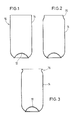
- each molding 10 consists essentially of an inwardly drawn, dome-shaped base 12 and a cylindrical wall 14, the upper, free end of which defines an opening.
- the molding 10 can be an intermediate product from a preform using one drawing and one closing expansion process have been produced, as described for example in FR-OS 25 67 066/85 10215.
- the wall of the molded article 10 has a thickness of, for example, 0.4 to 0.5 mm.
- the bottom 12 of the molding is noticeably thicker because it has not been influenced by the previous shaping processes, which have each led to a reduction in the thickness of the wall 14.
- the wall 14 of a molding 10 produced in the manner described above is oriented in the axial direction by the drawing process.
- the material forming the wall is oriented in the circumferential direction by the expansion process following the drawing process.
- the molding 10 by a stretch-blow process, as it is, for. B. is described in DE-AS 2 222 535.
- An orientation of the material forming the wall 14 is caused by an axial stretching process and the orientation of this material in the circumferential direction by the expansion process which is generally brought about by internal excess pressure.
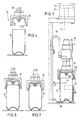
- the molding shown in FIG. 1 is subjected to a molding process in two successive treatment steps.
- the molded article 10 is first brought into a first treatment station 16, in which it is located below a first tool 15 and essentially axially aligned with it.
- This tool 15 is ring-shaped in cross section and closed on the upper side so that it has a bell-shaped or hood-shaped shape, the opening 17 of the hood or bell facing the molding 10.
- the inside diameter of the tool 15 takes from its opening 17 in the direction of its opposite, closed side such that the contour of the inner boundary of the wall 18 is adapted to the contour of the narrowed end section 20 to be produced on the molding 10.
- the tool 15 is carried by the piston rod 21 of a piston 22 which is guided within a pneumatic cylinder 24 and is pressurized on the molded article 10 in the direction of the latter during the molding of the narrowed end section 20. Furthermore, the interior of tool 15, which is open at the bottom, can be connected to a compressed air source. For this purpose, a channel 26 is provided for the supply of compressed air. The supply takes place via the hose line 38.
- the tool 15 consists essentially of an outer jacket 28 and an inner part 30 which is arranged coaxially to the jacket 28. (Fig. 5).
- a wire 32 is arranged between the two parts 28, 30 and serves as an electrical heating resistor for heating the inner part 30.
- the heating resistor 32 is connected to a voltage source via a line 36.
- the molding 10 brought into the first treatment station 16 by a transport slide 86 is aligned there to the tool 15 by the transport slide 86, a stop 88 and a fork 34 (FIG. 5).
- the first shaping step in which the upper end section 20 of the molding is narrowed, the latter is lowered onto the molding 10 from its initial position shown in FIG. 4.
- the inside diameter of the opening 17 of the tool 15 is slightly larger at its free end than the outside diameter of the essentially cylindrical molding 10.
- the tool 15 Since the tool 15 is heated via the wire 32, the contact between its inner wall 18 and the end section 20 of the wall 14 of the molding 10 leads to heat transfer, during which the thermoplastic material forming the end section 20 is softened. In this state, the end section 20 can be deformed using relatively low forces.
- the tool 15 is carried in the manner already described by the piston 22 which is guided within the pneumatic cylinder 24 and is acted upon in the direction of the molding 10 during the molding process.
- This arrangement has an automatic influence on the end section 20 of the molded article to be deformed and thus also on the subsequent, non-heated areas of the Wall 14 of the molding 10 acting forces, wherein the pressure acting on the piston can be easily adjusted so that the resulting forces are large enough to deform the softened end portion 20 of the molding 10, on the one hand, and on the other hand too small to prevent unwanted deformation of the molded article 10, in particular also in its non-heated area.
- the aforementioned action of the compressed air supplied through the duct 26 of the interior space enclosed by the molding 10 plays an important role, since it has a supporting function and in particular prevents the relatively slim molding 10 from buckling under the action of the pressure exerted by the tool 15.
- the inside of the end section 20 to be narrowed is acted on, so that during the shaping process in the course of the lowering movement of the tool 15 the end section 20 is under the action of outward forces which are evenly distributed over the circumference of the end section 20 and contribute to this to prevent the end portion 20 from being deformed irregularly, e.g. B. by formation of folds or the like.
- the outward forces caused by the internal overpressure are smaller than the inward forces transmitted through the inner wall 18 of the tool 15, but they are only fully effective where the inner wall 18 is in direct contact with the end section 20 of the molding 10.
- the tool 15 does not have a positive drive during its downward movement over the molding 10 for the purpose of deforming the end section 20 thereof, the path that the tool 15 travels in a suitable manner, e.g. B. limited by a stop. In this way it is ensured that the shape of the End section 20 in the first treatment step to the same extent is provided that the time required for this, which is essentially determined by the temperature of the tool 15 and the wall thickness of the end section 20, is available.
- the molding 10 has the shape shown in FIG. 2 of the drawing.
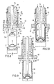
- the molding now provided with the narrowed section 20 is brought into the second treatment station 40 by a transport device (not shown in the drawing) (FIGS. 8-11).
- a two-part tool is arranged, which consists of a lower part 42 and a stamp 44 cooperating therewith.
- the lower part is plate-shaped and provided with a circular recess 45 (FIG. 11).
- the contour of the wall 46 delimiting this recess 45 corresponds to the final shape that the end section 20 is to receive in the second treatment station.
- the lower part 42 is divided into two halves 42a, 42b which can be displaced relative to one another in the horizontal plane.
- FIGS. 8 to 11 show the lower part 42 of the tool 42, 44 in its closed position.
- Both the lower part 42 and the punch 44 are provided with channels 48, 49 for the passage of a cooling medium.
- the stamp 44 is surrounded on the outside by an annular locking element 50 which is axially displaceable relative to the stamp 44 and by a coil spring 52 which is supported on the stamp 44 in a manner not shown, in the direction of the free end 54 of the stamp 44 is applied.
- a ring-shaped projection 56 is assigned to the annular locking element 50 and extends coaxially to the recess 45 on the upper side of the lower part 42.
- the end section 58 of the punch 44 is designed to taper conically towards its free end.
- This end section 58 is adjoined by a substantially cylindrical section 60, which at its end facing away from the free end 54 of the stamp 44 continues into a section 62 which is delimited in an arcuate manner in longitudinal section in such a way that it enlarges the outer diameter of the stamp in this section 62 has a course which corresponds to the desired course and the desired dimension of the flange to be molded on the hollow body.
- the arcuately delimited section 62 is delimited on its side facing away from the approximately cylindrical section 60 by a circumferential projection 66, the inner delimitation wall 68 of which abuts the section 62 approximately axially parallel to form an edge.
- the projection 66 cooperates with a circumferential groove 69, which is provided on the upper side of the lower part 42 of the tool coaxially to the recess 45.
- the wall 46 delimiting the recess 45 is essentially cylindrically delimited in its lower region.
- the diameter of the area 70 corresponds to the outer diameter of the wall 14 of the molding 10 in its area that remains undeformed.
- This essentially cylindrical region 70 is adjoined by a region 71 which tapers essentially conically in the direction of the plunger 44 and which corresponds to the transition between the portion of the wall 14 of the molding 10 which has remained undeformed and that after the treatment step has been carried out in the first treatment station 16 narrowest area of the end portion 20 of the Moldings 10 corresponds.
- This tapering area 71 is followed by a short, essentially cylindrically delimited area 72, the inside diameter of which is adapted to the outside diameter of the cylindrical section 60 of the stamp 44 such that an annular space remains between the two wall sections 72 on the one hand and 60 on the other hand the area of the wall 14 of the molding 10 located there is filled.
- a wall area 74 which has a larger diameter in longitudinal section in the direction of the punch 44, and is adapted in terms of its course and its dimension to the course and dimension of the section 62 to the punch 15, the wall area 74 of the lower part 42, on the one hand, and the wall area 62 of the plunger 44, on the other hand, run essentially parallel to one another and, in their effective end position according to FIG. 15, delimit an annular gap, the width of which in this area corresponds to the thickness of the portion 20 to be narrowed Flange 76 corresponds.
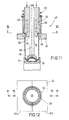
- the treatment station is assigned two holding means in the form of a bottom mandrel 77 and a holding mandrel 78, both of which can be displaced vertically independently of one another.
- the end faces of both the bottom mandrel 77 and the holding mandrel 78 are adapted to the shape of the bottom 12 of the molding 10.
- the holding mandrel 78 is carried by a rod 79 which axially in a longitudinal bore of the plunger 44 is movable.
- Both parts 78 and 79 are provided with a channel 89 for the supply of compressed air into the molding 10.
- the bottom mandrel 77 is coaxially surrounded by a support sleeve 90 which is vertically displaceable relative to the bottom mandrel 77.
- the bottom mandrel 77 and the holding mandrel 78 are each displaced in the direction of the bottom 12 of the molding 10 until both parts abut the bottom 12 and clamp it between them.
- the molding 10 is still in a position in which it is located below the lower part 42 of the tool. Due to the above-described clamping of the base 12 between the two holding means 77 and 78, the shape of the interacting parts also results in an axial alignment of the molding 10 with the tool.
- the support sleeve 90 After the base 12 has been clamped in, the support sleeve 90, the inside diameter of which is adapted to the outside diameter of the molded article 10, is shifted upwards to approximately the beginning of the narrowed region 20 (FIG. 9), which had been produced in the first treatment station 16. From this position, the two holding means 77, 78 and the support sleeve 90 are moved synchronously upward with the entrainment of the molding 10 until they have reached the position shown in FIG. 10 of the drawing. The lower part 42 of the tool is closed. In this position, it is locked from below by the support sleeve 90. For this purpose, an annular extension 91, which is conically delimited at least on one side, engages in a correspondingly delimited groove 92 of the lower part 42.
- the drawing shows that the contour of the tool 42 in the wall regions 70, 71 and 72 is adapted to the contour of the narrowed section 20 of the molding 10, so that the latter with its narrowed area 20 in the course of Upward movement of the parts 77, 78, 90 can be inserted into the recess 45 of the already closed lower part 42.
- the punch 44 When the molding 10 assumes the position shown in FIG. 10, the punch 44 is moved downward from its upper starting position shown in FIGS. 9, 10 and 13 into the recess 45 of the lower part 42 and into the opening of the molding 10 arranged coaxially therewith moved in.
- Fig. 13 of the drawing shows that the diameter of the free end 54 of the punch 44 is slightly smaller than the smallest diameter of the narrowed end portion 20 of the molding 10, so that the punch 44 first enters the opening of the molding 10 without the touch the wall bounding the opening. Possibly.
- the lower, conical end region 80 of the annular locking element 50 is brought into engagement with the projection 56 from the upper side of the lower part 42. Since the locking part 50 has reached its lower end position before the plunger 44 ends its downward movement, there is a relative displacement between the locking part 50 and the plunger 44, the helical spring 52, which is supported on the plunger 44 with its end facing away from the molding 10, being compressed.
- the locking element 50 and the extension 91 which also acts as a locking element
- the support sleeve has the task of locking the two halves 42a, 42b of the lower part 42 of the tool against one another in the closed position, so that the halves 42a, 42b remain closed during the subsequent pressing operations.
- the cylindrical section 60 of the plunger 44 then reaches the end section 20 of the molded article 10.
- the outer diameter of this cylindrical section 60 corresponds approximately to the smallest inner diameter of the narrowed area 20.
- compressed air is introduced into the interior of the molding 10 via the channel 89 in order to prevent the wall 14 of the molding 10 from buckling, in particular in the region 20 narrowed in the first treatment station 16, during the compression molding of the flange.
- Bulging of the molded article 10 to the outside is not possible, since its wall is supported on the outside by the support sleeve 90 which surrounds it from the outside (FIGS. 10 and 11).
- the internal overpressure in the molded article 10 also has the consequence that the portion of the region 20 which is not to be deformed to form the flange 76 is pressed against the wall of the lower part 42 and is cooled thereby.
- the lower end region of the projection 66 first enters the groove 69, as is shown in FIG. 15.
- the arrangement is such that the inner boundary wall 68 slides with little or no play on the inner boundary wall 82 of the groove 69 associated with the projection 66, so that the annular space 84 delimited by the two wall sections 62 on the punch 44 and 75 on the lower part 42 is closed on all sides, that is to say also to the outside, and a escape of thermoplastic material from the narrowed end section to the outside is prevented.
- the free edge of the narrowed section 20 is bent outwards to form a flange (FIG.
- a divergence of the material inwards in the direction of the undeformed wall area is likewise not possible or only to a negligible extent, since the annular gap between the cylindrical area 60 of the stamp 44 and the cylindrical area 72 of the lower part 42 is completely filled with material and because of it Small width has such a large flow resistance that evasion of material through this annular gap is not possible to a significant extent.
- the narrowed area 20 of the molded article 10 is thus introduced into the lower part 42 of the tool and the punch 44 is inserted into the narrowed area 20 quickly that before the material is shaped for the purpose of forming flange 76, the thermoplastic material does not cool to such an extent that deformation and flange formation could be adversely affected. This begins to a significant extent only after the stamp 44 has reached its end position shown in FIGS. 10 and 16.
- cooling medium flowing through the channels 48 and 49 which will generally be water, cooling then takes place to a temperature at which the thermoplastic material is again dimensionally stable, at least so quickly that the finished molding 10, which is now 3, can be removed from the second treatment station 40 if the molding 10 provided with the narrowed end section 20 in the first treatment station 16 is ready for further treatment in the second treatment station 40.
- the interior of the molding is relieved of pressure by opening a valve assigned to the channel 89.
- first stamp 44 with the conical locking element 50 and support sleeve 90 with conical locking element 91 are moved up and down and disengaged from the lower part 42.
- the lower part 42 of the tool is opened by moving the two halves 42a, 42b apart in the direction of the arrows 81, whereupon the molding 10 with its molded flange 76 can be demolded downward.
- bottom mandrel 77 and holding mandrel 78 are moved synchronously downward into the position according to FIG. 8, in which the molding is then transported by the transport device already mentioned or, if appropriate, by another one Transport device is detected, whereupon the bottom mandrel 77 down and the holding mandrel 78 are moved upward to release the molding 10.
- FIG. 3 shows that the free end of the flange 76 does not protrude beyond the contour of the hollow body 10 in the region of the largest diameter of the wall 14. This facilitates the transport of the finished moldings, which are consistently articles to be produced and processed in very large numbers, and consequently can also be transported in large numbers.
Abstract
Die Erfindung betrifft ein Verfahren und eine Vorrichtung zum Anformen eines Flansches an einen Hohlkörper aus thermoplastischem Kunststoff, dessen Wandung an einem Ende eine Öffnung begrenzt. Der die Öffnung begrenzende Endabschnitt der Wandung wird erwärmt und durch über den Umfang des Endabschnittes von außen auf diesen einwirkende Kräfte verengt, worauf an diesen verengten Endabschnitt durch einen Preßvorgang ein umlaufender Flansch angeformt wird.The invention relates to a method and a device for molding a flange onto a hollow body made of thermoplastic material, the wall of which delimits an opening at one end. The end section of the wall delimiting the opening is heated and narrowed by forces acting on the outside of the end section over the circumference thereof, whereupon a circumferential flange is formed on this narrowed end section by a pressing process.
Description
Die Erfindung betrifft ein Verfahren und eine Vorrichtung zum Anformen eines Flansches an einen Hohlkörper aus thermoplastischem Kunststoff, dessen im wesentlichen zylindrische Wandung an einem Ende eine Öffnung begrenzt.The invention relates to a method and a device for molding a flange onto a hollow body made of thermoplastic material, the essentially cylindrical wall of which delimits an opening at one end.
Bei dem mit dem Flansch zu versehenden Hohlkörper kann es sich z. B. um einen hohlen, im wesentlichen zylindrischen und mit einem Boden versehenen dosenförmigen Formling handeln, wobei der anzubringende Flansch die Funktion eines Bördelrandes hat, der zum Anbringen eines Deckels dient. Der mit dem Flansch zu versehene Formling kann unter Anwendung unterschiedlicher Verfahren hergestellt worden sein, von denen eines darin besteht, daß ein beispielsweise im Spritzgießverfahren hergestellter Vorformling, der eine im wesentlichen zylindrische Wandung, einen Boden und am anderen Ende eine Öffnung aufweist, durch Strecken der Wandung unter der Glasumwandlungstemperatur des den Vorformling bildenden Materials zu einem Zwischenerzeugnis umgeformt wird, welches dann an seinem offenen Ende vor-aufgeweitet und danach, ausgehend von diesem offenen, vor-aufgeweiteten Ende, zumindest über den größten Teil seiner Längserstreckung aufgeweitet und dann thermofixiert wird, worauf dann der vorerwähnte Flansch oder Bördelrand angeformt wird. Es ist aber auch möglich, einen derartigen dosenförmigen Hohlkörper unter Anwendung des Streck-Blasverfahrens herzustellen, wobei in einer Blasform ein zunächst im wesentlichen geschlosssener Hohlkörper hergestellt wird, worauf zur Herstellung der Öffnung der dem Boden abgewandte Endbereich des Formlings abgetrennt wird.In the hollow body to be provided with the flange, it can be, for. B. is a hollow, substantially cylindrical and bottomed can-shaped molding, wherein the flange to be attached has the function of a flange edge, which is used to attach a lid. The flange to be molded can be made using a variety of methods, one of which is that a preform, for example injection molded, having a generally cylindrical wall, bottom and opening at the other end, by stretching the Wall below the glass transition temperature of the material forming the preform is formed into an intermediate product, which is then pre-expanded at its open end and then, starting from this open, pre-expanded end, expanded at least over most of its longitudinal extent and then heat-set, whereupon the aforementioned flange or flanged edge is formed. However, it is also possible to produce a can-shaped hollow body of this type using the stretch-blow molding process, a hollow body initially being essentially closed being produced in a blow mold, whereupon the end region of the molded part facing away from the base is cut off to produce the opening.
In beiden Fällen entsteht ein Erzeugnis, bei dem zumindest das die Wandung bildende Material zur Verbesserung seiner mechanischen Eigenschaften orientiert ist.In both cases, a product is created in which at least the material forming the wall is oriented to improve its mechanical properties.
Unabhängig von der Art der Herstellung des mit einem Flansch zu versehenen Hohlkörpers und auch unabhängig von der weiteren Verwendung eines solchen Hohlkörpers wird es sich bei dem Enderzeugnis in den meisten Fällen um einen Massenartikel handeln, der in großen Stückzahlen zu fertigen ist, so daß der Ablauf des Verfahrens und die zu seiner Ausführung benutzte Vorrichtung möglichst einfach und übersichtlich und damit zuverlässig sein sollten.Regardless of the type of production of the hollow body to be provided with a flange and also regardless of the further use of such a hollow body, the end product will in most cases be a mass-produced article which can be manufactured in large quantities, so that the process of the method and the device used for its implementation should be as simple and clear and therefore reliable as possible.
Der Erfindung liegt die Aufgabe zugrunde, Verfahren und Vorrichtung der einleitend beschriebenen Art so auszugestalten, daß eine wirtschaftliche Massenfertigung möglich ist. Die durchzuführenden Bearbeitsvorgänge sollen nach Möglichkeit so aufeinander abgestimmt sein, daß eine optimale Nutzung der für die Behandlung der Hohlkörper erforderlichen Werkzeuge und sonstigen Einrichtungen möglich ist. Die einzelnen Arbeitsschritte sollen so ablaufen und aufeinander abgestimmt sein, daß die notwendigen Formgebungsvorgänge möglichst wenig Temperiervorgänge und -einrichtungen erfordern. Entsprechendes gilt auch für die räumliche Anordnung der für die Formgebungsvorgänge erforderlichen Werkzeuge zueinander. Ferner soll es möglich sein, daß der größte Durchmesser des anzuformenden Flansches und auch der des daran ggf. anzubringenden Deckels nicht größer ist als der Außendurchmesser des zylindrischen Bereichs des Hohlkörpers.The invention has for its object to design the method and apparatus of the type described in the introduction so that economical mass production is possible. The processing operations to be carried out should, if possible, be coordinated with one another in such a way that optimal use of the tools and other devices required for the treatment of the hollow bodies is possible. The individual work steps should take place and be coordinated with one another in such a way that the necessary shaping processes require as little temperature control processes and equipment as possible. The same also applies to the spatial arrangement of the tools required for the shaping processes. Furthermore, it should be possible that the largest diameter of the flange to be molded and also that of the cover that may be attached to it is not larger than the outside diameter of the cylindrical region of the hollow body.
Zur Lösung dieser Aufgabe schlägt die Erfindung vor, daß der die Öffnung begrenzende Endabschnitt der Wandung erwärmt und durch über den Umfang des Endabschnittes von außen auf diesen einwirkenden Kräfte verengt wird und danach an diesem verengten Endabschnitt durch einen Preßvorgang ein umlaufender Flansch angeformt wird. Vorteilhaft wird dabei so vorgegangen, daß das Verengen des Endabschnitts gleichzeitig mit dem Erwärmen desselben und in Abhängigkeit von dem dadurch bewirkten Erweichen des den Endabschnitt bildenden Materials erfolgt. Dies kann in der Weise geschehen, daß über den Endabschnitt ein im Querschnitt im wesentlichen ringförmiges erstes Werkzeug geführt wird, dessen innere Kontur sich entsprechend der am Endabschnitt durchzuführenden Verengung zu seinem dem Hohlkörper abgekehrten Ende hin verengt, wobei das Werkzeug unter der Einwirkung eines in Richtung auf den Hohlkörper wirkenden Federmittels steht und eine zum Erweichen des zu verengenden Bereichs geeignete Temperatur aufweist und die durch das Federmittel auf das Werkzeug ausgeübte Kraft so bemessen ist, daß eine das Verengen des Endbereichs bewirkende Verformung erst bei Erreichen einer bestimmten Temperatur und einer davon abhängigen Erweichung des unter der Einwirkung des Werkzeugs stehenden Endbereichs der Wandung eintritt.To achieve this object, the invention proposes that the end portion of the wall delimiting the opening is heated and narrowed by external forces acting on it over the circumference of the end portion and then a circumferential flange is formed on this narrowed end section by a pressing process. The procedure is advantageously such that the narrowing of the end section takes place simultaneously with the heating thereof and as a function of the softening of the material forming the end section. This can be done in such a way that an essentially ring-shaped first tool is passed over the end section, the inner contour of which narrows towards the end facing away from the hollow body in accordance with the constriction to be carried out at the end section, the tool under the action of a in the direction spring means acting on the hollow body and having a temperature suitable for softening the area to be narrowed and the force exerted by the spring means on the tool is such that a deformation causing the narrowing of the end area only when a certain temperature is reached and a softening dependent thereon of the end region of the wall, which is under the action of the tool.
Insbesondere bei diesem Behandlungsschritt ist zu berücksichtigen, daß der Hohlkörper insbesondere dann, wenn er als dosenförmiger Behälter verwendet wird, im allgemeinen sehr dünnwandig sein wird, so daß die am Hohlkörper angreifenden Kräfte in jedem Fall so dosiert und verteilt sein müssen, daß ungewollte und insbesondere unregelmäßige Verformungen wie beispielsweise Faltenbildung durch Stauchung in jedem Fall vermieden werden. Dies gilt insbesondere bei solchen Formgebungsvorgängen, bei denen der Formling nicht über seine gesamte Erstreckung durch besondere Stütz- und Haltelemente derartig abgestützt und gehalten wird, daß Verformungen des Hohlkörpers nur dann und dort erfolgen können, wenn bzw. wo die Stütz- und Haltelemente die zu verformenden Bereiche des Formlings für die Durchführung des Formgebungsvorganges freigeben, die übrigen Bereiche aber stützen und halten. Die vorbeschriebene Verfahrensweise gemäß der Erfindung hat den Vorteil, daß eine verhältnismäßig geringe Kraft ausreicht, die vom im Querschnitt ringförmigen Werkzeug auf den Endabschnitt der Wandung des Hohlkörpers zur Einwirkung kommt, um diesen Endabschnitt zu verengen. Der Ablauf dieses Verformungsvorganges erfolgt dabei ohne Zwangssteuerung derart, daß der Erweichungsgrad des zu verengenden Endabschnittes bei gegebener auf das Werkzeug einwirkender Kraft den Ablauf bestimmt. Es kann somit auf einen Zwangsantrieb des Werkzeugs verzichtet werden, wobei möglicherweise von Hohlkörper zu Hohlkörper gewisse Schwankungen bezüglich der Dauer des Verengungsvorganges auftreten können, wenngleich diese sehr gering bleiben unter der Voraussetzung, daß die Wandstärke des zu verengenden Abschnittes keinen oder nur geringen Schwankungen unterliegt. Um die Länge des verengten Endabschnitts in jedem Fall von Hohlkörper zu Hohlkörper konstant zu halten, ist es zweckmäßig, daß der vom Werkzeug während des Verengens zurückzulegende Weg, z. B. durch einen Anschlag, begrenzt wird.In this treatment step in particular, it must be taken into account that the hollow body will generally be very thin-walled, especially if it is used as a can-shaped container, so that the forces acting on the hollow body must in any case be metered and distributed such that unwanted and in particular Irregular deformations such as wrinkling due to compression can be avoided in any case. This applies in particular to those shaping processes in which the molding is not supported and held over its entire extent by special supporting and holding elements in such a way that deformations of the hollow body can only take place when and where the supporting and holding elements deforming areas of the molding for release the execution of the shaping process, but support and hold the remaining areas. The above-described procedure according to the invention has the advantage that a relatively small force is sufficient, which comes from the tool with an annular cross section to act on the end section of the wall of the hollow body in order to narrow this end section. The course of this deformation process takes place without positive control in such a way that the degree of softening of the end section to be narrowed determines the course for a given force acting on the tool. It is therefore possible to dispense with a forced drive of the tool, with certain fluctuations in the duration of the narrowing process possibly occurring from hollow body to hollow body, although these remain very small provided that the wall thickness of the section to be narrowed is subject to no or only slight fluctuations. In order to keep the length of the narrowed end section constant in each case from hollow body to hollow body, it is expedient that the path to be covered by the tool during the narrowing, e.g. B. is limited by a stop.
In jedem Fall ist es vorteilhaft, daß während des die Verengung bewirkenden Arbeitsschritts der Hohlkörper unter einem inneren Überdruck steht. Dies kann durch Druckluft geschehen, die zweckmäßig durch einen im für das Verengung benutzten Werkzeug befindlichen Kanal in den Hohlkörper eingeführt wird.In any case, it is advantageous that the hollow body is under an internal overpressure during the work step causing the narrowing. This can be done by compressed air, which is expediently introduced into the hollow body through a channel located in the tool used for the narrowing.
Der zweite Verformungsschritt, bei welchem der Flansch am verengten Endabschnitt des Hohlkörpers angeformt wird, erfolgt vorteilhaft unter Ausnutzung der Wärme, die im Verlauf des ersten Arbeitsschritts zur Verengung des Endabschnitts in letzteren eingebracht worden war. Dies ist jedenfalls dann möglich, wenn die einzelnen Arbeitsschritte so aufeinander abgestimmt sind, daß zwischen dem Ende des Verengungsvorganges und dem Preßvorgang zum Anbringen des Flansches nur eine kurze Zeitspanne liegt. Diese Verfahrensweise wird auch durch die Tatsache begünstigt, daß im ersten Verfahrensschritt das Temperieren, also Erwärmen des Endabschnittes durch das erste im Querschnitt ringförige Werkzeug erfolgt, welches bis zum Ende dieses Vorgebungsvorganges in Kontakt mit dem Endabschnitt bleibt und somit auch bis zum Ende des Verengungsvorganges Wärme auf den Endabschnitt des Hohlkörpers überträgt.The second deformation step, in which the flange is molded onto the narrowed end section of the hollow body, is advantageously carried out by utilizing the heat that was introduced into the latter in the course of the first work step to narrow the end section. In any case, this is possible if the individual work steps are coordinated so that there is only a short period of time between the end of the narrowing process and the pressing process for attaching the flange. This procedure is also favored by the fact that in the first step the temperature control, i.e. heating of the end section, is carried out by the first tool which is ring-shaped in cross section and remains in contact with the end section until the end of this presetting process and thus also heat until the end of the narrowing process transfers to the end portion of the hollow body.
Zum Anformen des Flansches kann der Hohlkörper mit seinem verengten Endabschnitt in den Bereich eines zweiten Werkzeugs gebracht werden das aus einem Unterteil mit einer Ausnehmung, deren Innenkontur an die Form des am Hohlkörper anzuformenden Flansches angepaßt ist, und einem Stempel besteht, dessen Endbereich in die Ausnehmung des Unterteils und den darin befindlichen Endabschnitt des Hohlkörpers eingeführt wird, und der mit der Hohlkörperwandung zuammenwirkende Bereich des Stempels so geformt ist, daß er beim Einführen den Endabschnitt des Hohlkörpers zunächst aufweitet und in der Endphase des Einführens der umlaufende Flansch zwischen Unterteil und Stempel preßgeformt und der verformte Bereich des Hohlkörpers soweit abgekühlt wird, daß er eine ausreichende Formstabilität erhält. Dabei kann das für das Anformen des Flansches verwendete Preßwerkzeug zugleich zur Abkühlung des verformten Bereichs der Wandung dienen. Im Bedarfsfall kann wenigstens eines der beiden Preßwerkzeuge gekühlt werden, beispielsweise durch eine in einem innerhalb des Preßwerkzeugs angeordnetes Kanalsystem geführte Kühlflüssigkeit. Ob eine solche besondere Kühlung notwendig oder zweckmäßig ist, hängt von den jeweiligen Umständen, z. B. von der Wanddicke des Hohlkörpers und damit von der Menge der abzuführenden Wärme ab. . Wenn der Hohlkörper vor den Verengungsvorgang einem Thermofixier vorgang unterzogen worden war, um ihm die für seine zukünftige Verwendung erforderliche Thermostabilität zu geben, sollten das Verengen des Endabschnitts des Hohlkörpers und das anschließende Preßformen des Flansches bei einer Temperatur erfolgen, die oberhalb der Thermofixiertemperatur liegt. Letztere kann bei Verwendung von beispielsweise PETP bei etwa 150° C liegen.To form the flange, the narrow end portion of the hollow body can be brought into the area of a second tool which consists of a lower part with a recess, the inner contour of which is adapted to the shape of the flange to be molded on the hollow body, and a punch, the end region of which is in the recess of the lower part and the end section of the hollow body located therein, and the region of the stamp interacting with the hollow body wall is shaped in such a way that it initially widens the end section of the hollow body during insertion and, in the final phase of insertion, the circumferential flange between the lower part and the stamp is press-formed and the deformed area of the hollow body is cooled to such an extent that it receives sufficient dimensional stability. The pressing tool used for forming the flange can also serve to cool the deformed area of the wall. If necessary, at least one of the two pressing tools can be cooled, for example by a cooling liquid guided in a channel system arranged inside the pressing tool. Whether such special cooling is necessary or appropriate depends on the respective circumstances, e.g. B. on the wall thickness of the hollow body and thus on the amount of heat to be removed. . If the hollow body before the narrowing process, a heat set had been subjected to the operation in order to give it the thermal stability required for its future use, the narrowing of the end section of the hollow body and the subsequent compression molding of the flange should take place at a temperature which is above the heat setting temperature. The latter can be around 150 ° C. when using PETP, for example.
Im allgemeinen wird es zweckmäßig sein, daß der Hohlkörper während des Preßformens des Flansches unter innerem Überdruck steht. Dadurch soll vermieden werden, daß die Wandung des Hohlkörpers unter der Einwirkung der für das Preßformen erforderlichen Kräfte oder eine andere ungewollte und kontrollierbare Verformung erfährt. Daraüber hinaus kann es vorteilhaft sein, während des Preßformens des Flansches die Hohlkörperwandung außenseitig durch eine sie umgebende Stützwandung abzustützen, so daß ein Ausbeulen des unter Überdruck stehenden Hohlkörpers vermieden wird. Die Verwendung einer solchen Stützwandung wird im allgemeinen abhängen von der Dicke der Hohlkörperwandung, da die Steifigkeit der letzteren mit zunehmender Wanddicke des Hohlkörpers größer wird.In general, it will be expedient that the hollow body is under internal pressure during the compression molding of the flange. This is to prevent the wall of the hollow body from experiencing any other unwanted and controllable deformation under the action of the forces required for the compression molding. In addition, it can be advantageous to support the outside of the hollow body wall by a surrounding support wall during the compression molding of the flange, so that bulging of the hollow body under pressure is avoided. The use of such a support wall will generally depend on the thickness of the hollow body wall, since the rigidity of the latter increases with increasing wall thickness of the hollow body.
Zur Erzielung einer hohen Produktivität ist es vorteilhaft, das Verengen des Endabschnittes des Hohlkörpers einerseits und das Preßformen dieses Flansches in zwei räumlich voneinander getrennten Behandlungsstationen durchzuführen, so daß beispielsweise in der eine Station der Endabschnitt eines Hohlkörpers verengt wird und gleichzeitig in der anderen Station an dem voraufgegangenen Hohlkörper der Flansch angeformt wird.To achieve high productivity, it is advantageous to carry out the narrowing of the end section of the hollow body on the one hand and the compression molding of this flange in two spatially separate treatment stations, so that, for example, the end section of a hollow body is narrowed in one station and at the same time in the other station on the previous hollow body of the flange is formed.
Die Vorrichtung zur Durchführuno des vorbeschriebenen Verfahrens ist zum Verengen des die Öffnung begrenzenden Abschnitts der Wandung des Hohlkörpers mit einem über den Endabschnitt zu führenden, beheizten, im Querschnitt ringförmigen ersten Werkzeug versehen, dessen Innendurchmesser an der dem Hohlkörper zugekehrten Stirnseite mindestens so groß ist wie der Außendurchmesser des unverformten Endabschnittes des Hohlkörpers und zu seiner vom Hohlkörper abgekehrten Seite hin abnimmt. Dieses erste Werkzeug kann zur besseren Handhabung, insbesondere aber auch zum Einführen von Druckluft in den Hohlkörper, an seiner dem Hohlkörper abgekehrten Seite verschlossen und mit einer Zuführung für Druckluft versehen sein. D. h., daß dieses im Querschnitt ringförmige erste Werkzeug etwa hauben- oder glockenförmig ausgebildet sein kann, wobei der Innenraum dieser Haube oder Glocke in der mit dem zu verengenden Endabschnitt des Hohlörpers zusammenwirkenden Position eine Fortsetzung des Innenraums des Hohlkörpers darstellt und der Gesamtraum durch das Werkzeug nach oben geschlossen ist, so daß ein im Gesamtraum erzeugter Überdruck durch Zuführen von Druckluft aufrechterhalten bleibt.The device for carrying out the above-described method is for narrowing the portion of the wall of the hollow body which delimits the opening with a End section to be guided, heated, cross-sectionally annular first tool, the inner diameter of which is at least as large as the outer diameter of the undeformed end section of the hollow body and decreases towards its side facing away from the hollow body on the end face facing the hollow body. For better handling, but in particular also for introducing compressed air into the hollow body, this first tool can be closed on its side facing away from the hollow body and can be provided with a supply for compressed air. That is to say that this first tool, which is annular in cross section, can be approximately hood-shaped or bell-shaped, the interior of this hood or bell in the position interacting with the end portion of the hollow body to be narrowed constituting a continuation of the interior of the hollow body and the entire space the tool is closed at the top, so that an overpressure generated in the entire space is maintained by supplying compressed air.
Als besonders vorteilhaft hat sich eine Ausführung herausgestellt, bei welcher das im Querschnitt ringförmige erste Werkzeug von der Kolbenstange eines Kolbens getragen wird, der innerhalb eines durch Druckluft beaufschlagten Zylinders geführt ist. Die Beaufschlagung des Kolbens ist dabei so gewählt, daß die resultierende, in Richtung auf den Hohlkörper wirkende Kraft einerseits ausreicht, den Endabschnitt bei ausreichender Erwärmung und dadurch bewirkter Erweichung zu verengen, andererseits jedoch keine unzulässigen Verformungen in den übrigen, nicht erwärmten Bereichen des Hohlkörpers bewirkt.An embodiment has proven to be particularly advantageous in which the first tool, which is ring-shaped in cross section, is carried by the piston rod of a piston which is guided within a cylinder acted upon by compressed air. The action on the piston is chosen so that the resulting force acting in the direction of the hollow body is sufficient on the one hand to narrow the end section with sufficient heating and the resulting softening, but on the other hand does not cause any unacceptable deformations in the other, unheated areas of the hollow body .
Zum Anformen des Flansches an dem verengten Endabschnitt ist ein zweites Werkzeug vorgesehen, das aus einem Unterteil mit einer kreisförmigen Ausnehmung, deren Begrenzung an die Kontur des anzuformenden Flansches angepaßt ist, sowie einem Stempel besteht, dessen dem Hohlkörper zugekehrter Endbereich in die Ausnehmung des Unterteils und den vom Unterteil umgebenden Endabschnitt des Hohlkörpers einführbar und so geformt ist, daß er an den Bereich des Unterteils angepaßt ist, welches den verengten Endabschnitt des Hohlkörpers und den daraus zu formenden Flansch außenseitig umgibt. Zweckmäßig ist der Stempel mit Mitteln zum Einführen von Druckluft in den Hohlkörper versehen. Der durch die Druckluft bewirkte Überdruck stützt die Wandung des Hohlkörpers innenseitig ab. Ferner ist es möglich, eine zum Hohlkörper koaxial angeordnete Hülse vorzusehen, deren Innendurchmesser an den Außendurchmesser des Hohlkörpers angepaßt ist, und die Hülse relativ zum Hohlkörper axial verschiebbar ist und in eine Position gebracht werden kann, in welcher sie die Hohlkörperwandung über zumindest den größten Teil ihrer axialen Erstreckung passend umgibt, um so auch eine außenseitige Abstützung der Hohlkörperwandung zu bewirken.To form the flange on the narrowed end section, a second tool is provided, which consists of a lower part with a circular recess, the Limitation is adapted to the contour of the flange to be molded, and there is a stamp, the end area facing the hollow body is insertable into the recess of the lower part and the end section surrounding the lower part and is shaped so that it is adapted to the area of the lower part, which surrounds the narrowed end portion of the hollow body and the flange to be formed therefrom on the outside. The stamp is expediently provided with means for introducing compressed air into the hollow body. The excess pressure caused by the compressed air supports the inside of the wall of the hollow body. Furthermore, it is possible to provide a sleeve arranged coaxially with the hollow body, the inner diameter of which is adapted to the outer diameter of the hollow body, and the sleeve is axially displaceable relative to the hollow body and can be brought into a position in which it covers the hollow body wall over at least the largest part their axial extent suitably surrounds so as to bring about an external support of the hollow body wall.
Das Unterteil des Werkzeugs zum Anformen des Flansches ist vorteilhaft zum Zwecke des Entformens geteilt, wobei am Stempel diesem gegenüber axial verschiebbar ein ringförmiges Verriegelungselement angebracht sein kann, welches im Zuge der Bewegung des Stempels in Richtung auf das Unterteil mit beiden Teilen des Unterteils in Eingriff gebracht wird, bevor das Unterteil im Zuge des Formgebungsvorganges durch Kräfte durch den Stempel beaufschlagt wird. In gleicher Weise kann auch die zur außenseitigen Abstützung des Hohlkörpers dienende Hülse in ihrer wirksamen Lage mit dem Unterteil des Werkzeugs in Eingriff gebracht werden, um so eine zusätzliche Verriegelung zu bewirken, die ein Öffnen des Unterteils während des Preßformens des Flansches verhindert.The lower part of the tool for shaping the flange is advantageously divided for the purpose of demolding, whereby an annular locking element can be axially displaceably attached to the stamp, which in the course of the movement of the stamp in the direction of the lower part is brought into engagement with both parts of the lower part is before the lower part is subjected to forces by the stamp in the course of the shaping process. In the same way, the sleeve serving for the external support of the hollow body can be brought into engagement in its effective position with the lower part of the tool, so as to bring about an additional locking which prevents the lower part from opening during the compression molding of the flange.
Es ist zweckmäßig, das erste, im Querschnitt ringförmige Werkzeug zum Verengen des Endabschnittes einerseits und das zweite Werkzeug zum Ausformen des Flansches andererseits in zwei in einen Abstand voneinander aufweisenden Behandlungsstation anzuordnen, so daß in jeder der Behandlungsstationen jeweils ein Hohlkörper behandelt werden kann. Der zweckmäßig horizontale Abstand zwischen beiden Stationen sollte möglichst kurz sein, so daß der Transport von der ersten Station, in welcher die Verengung durchgeführt wird, in die zweite Station, in welcher der Flansch angeformt wird, wenig Zeit beansprucht.It is expedient to arrange the first tool, which is annular in cross section, for narrowing the end section on the one hand and the second tool for forming the flange, on the other hand, in two treatment stations which are at a distance from one another, so that a hollow body can be treated in each of the treatment stations. The appropriate horizontal distance between the two stations should be as short as possible, so that the transport from the first station, in which the narrowing is carried out, to the second station, in which the flange is formed, takes up little time.
In der Zeichnung ist als Ausführungsbeispiel der Erfindung eine Vorrichtung zum Herstellen von Dosen dargestellt. Es zeigen:
- Fig. 1 die Seitenansicht eines Hohlkörpers aus thermoplastischem Kunststoff in Gestalt eines ein Zwischenerzeugnis darstellender Formlings für die Herstellung von Dosen vor Durchführung der Behandlungsschritte gemäß der Erfindung,
- Fig. 2 die Seitenansicht des Formlings gemäß Fig. 1 nach Durchführung des ersten Behandlungsschritts mit verengtem Endabschnitt,
- Fig 3 die Seitenansicht des Formlings gemäß Fig. 1 und 2 nach Durchführung des zweiten Behandlungsschrittes mit daran angeformtem Bördelflansch,
- Fig. 4 im Schema die Seitenansicht des Formlings in einer ersten Behandlungsstation mit dem Behandlungswerkzeug in seiner Ausgangsposition,
- Fig. 5 eine der Fig. 4 entsprechende Darstellung mit dem Werkzeug in einer Zwischenposition,
- Fig. 6 eine der Fig. 5 entsprechende Darstellung mit dem Werkzeug in einer weiteren Zwischenposi tion,
- Fig. 7 eine der Fig. 5 entsprechende Darstellung mit dem Werkzeug in seiner Endposition,
- Fig. 8 einen Längsschnitt des Formlings während des Einbringens in die zweite Behandlungsstation,
- Fig. 9 eine der Fig. 8 entsprechende Darstellung eines Zwischenstadiums beim Einbringen,
- Fig. 10 eine der Fig. 8 entsprechende Darstellung mit dem Formling in der zweiten Behandlungsstation und den Werkzeugen der zweiten Behandlungsstation in ihrer jeweiligen Ausgangsposition,
- Fig. 11 eine der Fig. 10 entsprechende Darstellung mit den beiden Werkzeugen in ihrer jeweiligen Endstellung,
- Fig. 12 eine Ansicht des unteren Werkzeugs der Fig. 11 in Richtung der Pfeile XII-XII,
- Fig. 13 einen Ausschnitt aus Fig. 10 in größerem Maßstab,
- Fig. 14 eine der Fig. 13 entsprechende Darstellung mit den zusammenwirkenden Teilen der beiden Werkzeuge in einer Zwischenposition,
- Fig. 15 die in den Fig. 13 und 14 dargestellten Teile in einer weiteren Zwischenposition,
- Fig. 16 die in den Fig. 12 -1 4 dargestellten zusammenwirkenden Teile in ihrer Endposition.
- 1 is a side view of a hollow body made of thermoplastic material in the form of an intermediate product for the manufacture of cans before carrying out the treatment steps according to the invention,
- 2 shows the side view of the molding according to FIG. 1 after the first treatment step has been carried out with a narrowed end section,
- 3 shows the side view of the molded article according to FIGS. 1 and 2 after the second treatment step has been carried out with a flange flange formed thereon,
- 4 shows a schematic side view of the molded article in a first treatment station with the treatment tool in its starting position,
- 5 shows a representation corresponding to FIG. 4 with the tool in an intermediate position,
- FIG. 6 shows a representation corresponding to FIG. 5 with the tool in a further intermediate position tion,
- 7 a representation corresponding to FIG. 5 with the tool in its end position,
- 8 shows a longitudinal section of the molded article while it is being introduced into the second treatment station,
- 9 shows a representation corresponding to FIG. 8 of an intermediate stage during introduction,
- 10 shows a representation corresponding to FIG. 8 with the molding in the second treatment station and the tools of the second treatment station in their respective starting position,
- 11 shows a representation corresponding to FIG. 10 with the two tools in their respective end positions,
- 12 is a view of the lower tool of FIG. 11 in the direction of arrows XII-XII,
- 13 shows a detail from FIG. 10 on a larger scale,
- 14 shows a representation corresponding to FIG. 13 with the interacting parts of the two tools in an intermediate position,
- 15 shows the parts shown in FIGS. 13 and 14 in a further intermediate position,
- Fig. 16 shows the cooperating parts shown in Figs. 12 -1 4 in their end position.
Die gemäß dem Verfahren nach der Erfindung zu behandelnden Hohlkörper bzw. Formlinge weisen bei dem im folgenden beschriebenen Ausführungsbeispiel die in Fig. 1 der Zeichnung dargestellte Gestalt auf. Jeder Formling 10 besteht im wesentlichen aus einem nach innen eingezogenen, kalottenförmigen Boden 12 und einer zylindrischen Wandung 14, deren oberes, freies Ende eine Öffnung begrenzt. Der Formling 10 kann als Zwischenerzeugnis aus einem Vorformling unter Anwendung eines Ziehvorganges und eines an schließenden Aufweitvorganges hergestellt worden sein, wie er beispielsweise in der FR-OS 25 67 066/85 10215 beschrieben ist. Die Wandung des Formlings 10 weist eine Stärke von beispielsweise 0,4 bis 0,5 mm auf. Der Boden 12 des Formlings ist merklich dicker, da er durch die vorangegangenen Formgebungsvorgänge, die jeweils zu einer Verringerung der Dicke der Wandung 14 geführt haben, nicht beeinflußt worden ist. Die Wandung 14 eines in der vorbeschriebenen Weise hergestellten Formlings 10 ist durch den Ziehvorgang in axialer Richtung orientiert. Eine Orientierung des die Wandung bildenden Materials in Umfangsrichtung erfolgt durch den an den Ziehvorgang anschließenden Aufweitvorgang.The hollow bodies or moldings to be treated according to the method according to the invention have the shape shown in FIG. 1 of the drawing in the exemplary embodiment described below. Each
Es ist aber auch möglich, den Formling 10 durch einen Streck-Blasvorgang herzustellen, wie er z. B. in der DE-AS 2 222 535 beschrieben ist. Dabei wird eine Orientierung des die Wandung 14 bildenden Materials durch einen axialen Streckvorgang und die Orientierung dieses Materials in Umfangsrichtung durch den im allgemeinen durch inneren Überdruck bewirkten Aufweitvorgang verursacht.However, it is also possible to produce the
Der in Fig. 1 dargestellte Formling wird in zwei aufeinanderfolgenden Behandlungsschritten jeweils einem Formgebungsvorgang unterzogen. Dazu wird der Formling 10 zunächst in eine erste Behandlungsstation 16 gebracht, in welcher er sich unterhalb eines ersten Werkzeugs 15 und zu diesem im wesentlichen axial ausgerichtet befindet. Dieses Werkzeug 15 ist im Querschnitt ringförmig ausgebildet und oberseitig verschlossen, so daß es eine glocken- oder haubenförmige Gestalt aufweist, wobei die Öffnung 17 der Haube oder Glocke dem Formling 10 zugekehrt ist. Der Innendurchmesser des Werkzeugs 15 nimmt von seiner Öffnung 17 in Richtung auf seine gegenüberliegende, verschlossene Seite derart ab, daß die Kontur der inneren Begrenzung der Wandung 18 der Kontur des am Formling 10 herzustellenden verengten Endabschnittes 20 angepaßt ist.The molding shown in FIG. 1 is subjected to a molding process in two successive treatment steps. For this purpose, the molded
Das Werkzeug 15 wird von der Kolbenstange 21 eines Kolbens 22 getragen, der innerhalb eines pneumatischen Zylinders 24 geführt und während des Formens des verengten Endabschnittes 20 am Formling 10 in Richtung auf letzteren druckbeaufschlagt ist. Ferner ist der nach unten offene Innenraum des Werkzeugs 15 an eine Druckluftquelle anschließbar. Zu diesem Zweck ist ein Kanal 26 für die Zuleitung von Druckluft vorgesehen. Die Zuführung erfolgt über die Schlauchleitung 38.The
Das Werkzeug 15 besteht im wesentlichen aus einem äußeren Mantel 28 und einem inneren Teil 30, das koaxial zum Mantel 28 angeordnet ist. (Fig. 5). Zwischen beiden Teilen 28, 30 ist ein Draht 32 angeordnet, der als elektrischer Heizwiderstand zur Erwärmung des inneren Teiles 30 dient. Der Anschluß des Heizwiderstands 32 an eine Spannungsquelle erfolgt über eine Leitung 36.The
Der durch einen Tansportschieber 86 in die erste Behandlungsstation 16 gebrachte Formling 10 wird dort durch den Transportschieber 86, einen Anschlag 88 und eine Gabel Gabel 34 (Fig. 5) zum Werkzeug 15 ausgerichtet. Letzteres wird zur Durchführung des ersten Formgebungsschritts, bei welchem der obere Endabschnitt 20 des Formlings verengt wird, aus seiner in Fig. 4 dargestellten Ausgangslage auf den Formling 10 abgesenkt. Der Innendurchmesser der Öffnung 17 des Werkzeugs 15 ist an dessen freiem Ende etwas größer als der Außendurchmesser des im wesentlichen zylindrischen Formlings 10. Im Verlauf der Absenkbewegung des Werkzeugs 15 erfolgt zunächst eine Feinausrichtung des Formlings 10, so daß dieser, nachdem im Zuge der Absenkbewegung eine erste Berührung zwischen der Endabschnitt 20 und der inneren Begrenzungswandung 18 des Werkzeugs 15 stattgefunden hat, der Formling 10 genau koaxial zum Werkzeug 15 ausgerichtet ist. Im Verlauf dieses Ausrichtens in der ersten Phase der Abwärtsbewegung des Werkzeugs 15 werden kaum axiale Kräfte auf den Formling 10 einwirken, der, wie bereits erwähnt, sehr dünnwandig ist. Spätestens nach der ersten Berührung zwischen Werkzeug 15 und dem Endbereich 21 des Formlings 10 wird durch die Kanal 26 Druckluft in den Formling 10 eingeführt, so daß dieser unter innerem Überdruck steht. Damit wird eine Abstützung der Wandung 14 des Formlings 10 bewirkt, auf die im Zuge des weiteren Absenkens des Formlings 15 nun axiale und auch radiale Kräfte zur Einwirkung kommen.The
Da das Werkzeug 15 über den Draht 32 beheizt ist, führt der Kontakt zwischen seiner Innenwandung 18 und dem Endabschnitt 20 der Wandung 14 des Formlings 10 zu einem Wärmeübergang, in dessen Verlauf das den Endabschnitt 20 bildende thermoplastische Material eine Erweichung erfährt. In diesem Zustand ist der Endabschnitt 2o unter Anwendung relativ geringer Kräfte verformbar. Um in jedem Fall sicherzustellen, daß die Bewegung des Werkzeugs 15 nach unten über den Formling 10 und das Ausmaß der Erwärmung des Endabschnitts 20 derart aufeinander abgestimmt sind, daß das Werkzeug 15 nur entsprechend dem Ausmaß der Erwärmung und der damit bewirkten Verformbarkeit des Endabschnitt 20 über den Formling 10 sich nach unten bewegt, wird das Werkzeug 15 in der bereits beschriebenen Weise vom Kolben 22 getragen, der innerhalb des pneumatischen Zylinders 24 geführt und während des Formgebungsvorganges in Richtung auf den Formling 10 beaufschlagt ist. Diese Anordnung bewirkt eine selbsttätige Beeinflussung der auf den zu verformenden Endabschnitt 20 des Formlings und damit auch auf die anschließenden, nicht erwärmten Bereiche der Wandung 14 des Formlings 10 einwirkenden Kräfte, wobei der auf den Kolben einwirkende Druck ohne weiteres so eingestellt werden kann, daß die resultierenden Kräfte einerseits groß genug ist, den erweichten Endabschnitt 20 des Formlings 10 zu verformen, andererseits zu klein sind, um eine ungewollte Verformung des Formlings 10, insbesondere auch in dessen nicht erwärmtem Bereich, zu verursachen. Dabei spielt die bereits erwähnte Beaufschlagung des vom Formling 10 umschlossenen Innenraums mit der durch den Kanal 26 zugeführten Druckluft eine wesentliche Rolle, da diese eine Stützfunktion hat und insbesondere ein Einknicken des relativ schlanken Formlings 10 unter der Einwirkung des durch das Werkzeug 15 ausgeübten Druckes vermeidet. Gleichermaßen wird auch die Innenseite des zu verengenden Endabschnitts 20 beaufschlagt, so daß während des Formgebungsvorganges im Zuge der Absenkbewegung des Werkzeuges 15 der Endabschnitt 20 unter der Einwirkung von nach außen gerichteten Kräften steht, die über den Umfang des Endabschnitt 20 gleichmäßig verteilt sind und dazu beitragen zu verhindern, daß der Endabschnitt 20 unregelmäßig verformt wird, z. B. durch Bildung von Falten oder dgl. Die durch den inneren Überdruck verursachten, nach außen gerichteten Kräfte sind zwar kleiner als die durch die Innenwandung 18 des Werkzeugs 15 übertragenen, nach innen gerichteten Kräfte, die jedoch nur dort voll wirksam werden, wo die Innenwandung 18 unmittelbar mit dem Endabschnitt 20 des Formlings 10 in Berührung ist.Since the
Wenngleich das Werkzeug 15 bei seiner Abwärtsbewegung über den Formling 10 zwecks Verformung von dessen Endabschnitt 20 keinen Zwangsantrieb besitzt, ist der Weg, den das Werkzeug 15 dabei zurücklegt, in geeigneter Weise, z. B. durch einen Anschlag, begrenzt. Auf diese Weise ist sichergestellt, daß an jedem Formling 10 die Formgebung des Endabschnitts 20 im ersten Behandlungsschritt in gleichem Ausmaß erfolgt unter der Voraussetzung, daß die dafür erforderliche Zeit, die im wesentlichen von der Temperatur des Werkzeugs 15 und der Wandstärke des Endabschnittes 20 bestimmt wird, zur Verfügung steht.Although the
Am Ende des ersten Verformungsschritts weist der Formling 10 die in Fig. 2 der Zeichnung dargestellte Gestalt auf.At the end of the first deformation step, the
Nach Beendigung der Behandlung des Formlings 10 in der Behandlungsstation 16 wird der nun mit dem verengten Abschnitt 20 versehene Formling durch eine in der Zeichnung nicht dargestellte Transporteinrichtung in die zweite Behandlungsstation 40 gebracht (Fig. 8 - 11). In dieser Behandlungsstation 40 ist ein zweiteiliges Werkzeug angeordnet, welches aus einem Unterteil 42 und einem damit zusammenwirkenden Stempel 44 besteht. Das Unterteil ist plattenförmig ausgebildet und mit einer kreisförmigen Ausnehmung 45 versehen (Fig. 11). Die Kontur der diese Ausnehmung 45 begrenzenden Wandung 46 (Fig. 8) entspricht der endgültigen Form, die der Endabschnitt 20 in der zweiten Behandlungsstation erhalten soll. Das Unterteil 42 ist in zwei Hälften 42a, 42b unterteilt, die in horizontaler Ebene relativ gegeneinander verschiebbar sind. In den Figuren 8 bis 11 ist das Unterteil 42 des Werkzeugs 42, 44 in seiner geschlossenen Position dargestellt.After the treatment of the
Sowohl Unterteil 42 als auch Stempel 44 sind mit Kanälen 48, 49 für den Durchgang eines Kühlmediums versehen.Both the
Der Stempel 44 ist außenseitig von einem ringförmigen Verriegelungselement 50 umgeben, welches gegenüber dem Stempel 44 axial verschiebbar ist und durch eine Schraubenfeder 52, die sich in nicht dargestellter Weise am Stempel 44 abstützt, in Richtung auf das freie Ende 54 desStempels 44 beaufschlagt ist. Dem ringförmigen Verriegelungselement 50 ist ein umlaufender Vorsprung 56 zugeordnet, der an der Oberseite des Unterteils 42 koaxial zu dessen Ausnehmung 45 verläuft.The
Der Endabschnitt 58 des Stempels 44 ist zu seinem freien Ende hin sich konisch verjüngend ausgebildet. An diesen Endabschnitt 58 schließt sich ein im wesentlichen zylindrischer Abschnitt 60 an, der an seinem dem freien Ende 54 des Stempels 44 abgekehrten Ende sich in einen Abschnitt 62 fortsetzt, der im Längsschnitt bogenförmig derart begrenzt ist, daß er unter Vergrößerung des Außendurchmessers des Stempels in diesem Abschnitt 62 einen Verlauf aufweist, der dem gewünschten Verlauf und der gewünschten Abmessung des am Hohlkörper anzuformenden Flansches enrspricht. der bogenförmig begrenzte Abschnitt 62 ist an seiner dem etwa zylindrischen Abschnitt 60 abgekehrten Seite durch einen umlaufenden Vorsprung 66 begrenzt, dessen innere Begrenzungswandung 68 etwa achsparallel unter Bildung einer Kante, an den Abschnitt 62 stößt. Der Vorsprung 66 wirkt mit einer umlaufenden Nut 69 zusammen, die an der Oberseite des Unterteils 42 des Werkzeugs koaxial zur Ausnehmung 45 angebracht ist.The
Die die Ausnehmung 45 begrenzende Wandung 46 ist in ihrem unteren Bereich im wesentlichen zylindrisch begrenzt. Der Durchmesser des Bereichs 70 entspricht dem Außendurchmesser der Wandung 14 des Formlings 10 in deren unverformt bleibendem Bereich. An diesen im wesentlichen zylindrischen Bereich 70 schließt sich ein in Richtung auf den Stempel 44 im wesentlichen konisch sich verjüngender Bereich 71 an, der dem Übergang zwischen dem unverformt gebliebenen Abschnitt der Wandung 14 des Formlings 10 und dem nach Durchführung des Behandlungsschritts in der ersten Behandlungsstation 16 engsten Bereich des Endabschnittes 20 des Formlings 10 entspricht. An diesen sich verjüngenden Bereich 71 schließt sich ein kurzer, im wesentlichen zylindrisch begrenzter Bereich 72 an, dessen Innendurchmesser dem Außendurchmesser des zylindrischen Abschnittes 60 des Stempels 44 derart angepaßt ist, daß zwischen den beiden Wandabschnitten 72 einerseits und 60 andererseits ein Ringraum verbleibt, der von dem dort befindlichen Bereich der Wandung 14 des Formlings 10 ausgefüllt wird.The
Oberhalb des im wesentlichen zylindrisch begrenzten Bereiches 72 der Wandung 46 schließt sich ein Wandbereich 74 an, der im Längsschnitt in Richtung auf den Stempel 44 einen größer werdenden Durchmesser aufweist, und bezüglich seines Verlaufs und seiner Abmessung am Verlauf und Abmessung des Abschnitts 62 am Stempel angepaßt ist, wobei der Wandbereich 74 des Unterteils 42 einerseits und der Wandbereich 62 des Stempels 44 andererseits zueinander im wesentlichen parallel verlaufen und in ihrer wirksamen Endposition gemäß Fig. 15 einen Ringspalt begrenzen, dessen Breite in diesem Bereich der Dicke des an den verengten Abschnitt 20 anzuformenden Flansches 76 entspricht.Above the essentially cylindrically delimited
Nachdem der Formling 10 aus der ersten Behandlungsstation 16 in die zweite Behandlungsstation 40 gebracht worden ist, nimmt er zunächst die in Fig. 8 dargestellte Lage ein, wobei er von einem nicht dargestellten Haltemittel, beispielsweise einem Greifer der nicht dargestelltem Transporteinrichtung gehalten wird. Der Behandlungsstation sind zwei Haltemittel in Form eines Bodendornes 77 und eines Haltedorns 78 zugeordnet, die beide unabhängig voneinander vertikal verschiebbar sind. Die Stirnseiten sowohl des Bodendornes 77 als auch des Haltedornes 78 sind an die Form des Bodens 12 des Formlings 10 angepaßt. Der Haltedorn 78 wird von einer Stange 79 getragen, die in einer Längsbohrung des Stempels 44 diesem gegenüber axial verschiebbar ist. Beide Teile 78 und 79 sind mit einem Kanal 89 für die Zuführung von Druckluft in den Formling 10 hinein versehen. Der Bodendorn 77 ist von einer Stützhüle 90 koaxial umgeben, die gegenüber dem Bodendorn 77 vertikal verschiebbar ist.After the
Sobald der Formling 10 die in Fig. 8 der Zeichnung dargestellte Lage einnimmt, werden Bodendorn 77 und Haltedorn 78 jeweils in Richtung auf den Boden 12 des Formlings 10 verschoben, bis beide Teile am Boden 12 anliegen und diesen zwischen sich einklemmen. Dabei befindet sich der Formling 10 noch in einer Position, in der er sich unterhalb des Unterteiles 42 des Werkzeuges befindet. Durch das vorbeschriebene Einklemmen des Bodens 12 zwischen beiden Haltemitteln 77 und 78 erfolgt aufgrund der Form der dabei zusammenwirkenden Teile auch eine axiale Ausrichtung des Formlings 10 zum Werkzeug. Nach dem Einklemmen des Bodens 12 wird die Stützhülse 90, deren Innendurchmesser dem Außendurchmesser des Formlings 10 angepaßt ist, nach oben bis ungefähr zum Beginn des verengaten Bereichs 20 verschoben (Fig. 9), der in der ersten Behandlungsstation 16 hergestellt worden war. Aus dieser Position werden die beiden Haltemittel 77, 78 und die Stützhüle 90 synchron unter Mitnahme des Formlings 10 nach oben verschoben, bis sie die in Fig. 10 der Zeichnung dargestellte Lage erreicht haben. Das Unterteil 42 des Werkzeugs ist dabei geschlossen. Es wird in dieser Lage von unten durch die Stützhülse 90 verriegelt. Zu diesem Zweck greift ein zumindest einseitig konisch begrenzter ringförmiger Fortsatz 91 in eine entsprechend begrenzte Nut 92 des Unterteils 42 ein.As soon as the
Die Zeichnung läßt erkennen, daß die Kontur des Werkzeugs 42 in den Wandbereichen 70, 71 und 72 an die Kontur des verengten Abschnitts 20 des Formlings 10 angepaßt ist, so daß letzterer mit seinem verengten Bereich 20 im Zuge der Aufwärtsbewegung der Teile 77, 78, 90 in die Ausnehmung 45 des bereits geschlossenen Unterteils 42 eingeschoben werden kann.The drawing shows that the contour of the
Wenn der Formling 10 die in Fig.10 dargestellte Lage einnimmt, wird der Stempel 44 aus seiner in den Fig. 9, 10 und 13 dargestellten oberen Ausgangslage nach unten in die Ausnehmung 45 des Unterteils 42 sowie in die Öffnung des dazu koaxial angeordnete Formlings 10 hineinbewegt. Insbesondere Fig. 13 der Zeichnung läßt erkennen, daß der Durchmesser des freien Endes 54 des Stempels 44 geringfügig kleiner ist als der kleinste Durchmesser des verengten Endabschnittes 20 des Formlings 10, so daß der Stempel 44 zunächst in die Öffnung des Formlings 10 eintritt, ohne die die Öffnung begrenzende Wandung zu berühren. Ggf. kann während des Einführens des konischen Endabschnittes 58 des Stempels 44 noch eine Feinausrichtung des Formlings 10 zum Stempel 44 erfolgen, wenngleich dies im allgemeinen nicht erforderlich ist, da die axiale Ausrichtung des Formlings 10 zum Unterteil 42 des Werkzeugs und damit auch zu dessen Stempel 44 beim Einführen des verengten Endabschnittes in das Unterteil 42 oder spätestens beim Hochfahren der Stützhülse 90 bewirkt wird.When the
Während der ersten Phase der Abwärtsbewegung des Stempels 44 wird der untere, konische Endbereich 80 des ringförmigen Verriegelungselementes 50 mit dem Vorsprung 56 ab der Oberseite des Unterteils 42 in Eingriff gebracht. Da das Verriegelungsteil 50 seine untere Endlage erreicht hat, bevor der Stempel 44 seine Abwärtsbewegung beendet, erfolgt eine Relativverschiebung zwischen Verriegelungsteil 50 und Stempel 44, wobei die Schraubenfeder 52, die mit ihrem dem Formling 10 abgekehrten Ende am Stempel 44 abgestützt ist, zusammengedrückt wird. Das Verriegelungselement 50 und der ebenfalls als Verriegelungselement wirkende Fortsatz 91 an der Stützhülse haben die Aufgabe, die beiden Hälften 42a, 42b des Unterteils 42 des Werkzeugs in der Schließlage gegeneinander zu verriegeln, so daß bei den nachfolgenden Preßvorgänge die Hälften 42a, 42b geschlossen bleiben. Dies wird aufgrund der konischen Begrenzung des Vorsprungs 56 an dessen Außenseite und der daran angepaßten konischen Begrenzung des Endbereichs 80 des Verriegelungselementes 50 und entsprechende Begrenzungen des Fortsatzes 91 an der Stützhülse 90 und damit zusammenwirkenden Nut 92 erreicht.During the first phase of the downward movement of the
Im Zuge der weiteren Abwärtsbewegung des Stempels 44 gelangt dann der zylindrische Abschnitt 60 des Stempels 44 in den Endabschnitt 20 des Formlings 10. Der Außendurchmesser dieses zylindrischen Abschnitts 60 stimmt etwa überein mit dem kleinsten Innendurchmesser des verengten Bereichs 20. Nachdem der Stempel 44 etwa die Position gemäß Fig. 14 erreicht hat, wird über den Kanal 89 Druckluft in das Innere des Formlings 10 eingeführt, um ein Einknicken der Wandung 14 des Formlings 10, insbesondere in den in ersten Behandlungsstation 16 verengten Bereich 20 während des Preßformens des Flansches zu verhindern. Ein Ausbeulen des Formlings 10 nach außen ist nicht möglich, da seine Wandung durch die letztere von außen umschließende Stützhülse 90 außenseitig abgestützt wird (Fig. 10 und 11). Der innere Überdruck im Formling 10 hat weiterhin zur Folge, daß der nicht zur Bildung des Flansches 76 zu verformende Abschnitt des Bereiches 20 an die Wandung des Unterteils 42 angedrückt und durch diese gekühlt wird.In the course of the further downward movement of the
Im Zuge der weiteren Abwärtsbewegung tritt zunächst der untere Endbereich des Vorsprungs 66 in die Nut 69 ein, wie dies in Fig. 15 dargestellt ist. Dabei ist die Anordnung so getroffen, daß die innere Begrenzungswand 68 ohne oder nur mit ganz geringem Spiel an der inneren Begrenzungswandung 82 der dem Vorsprung 66 zugeordneten Nut 69 gleitet, so daß der von den beiden Wandabschnitten 62 am Stempel 44 und 75 am Unterteil 42 begrenzte Ringraum 84 allseits, also auch nach außen, abgeschlossen ist und ein Ausweichen von thermoplastischem Material aus dem verengten Endabschnitt nach außen verhindert wird. Im Zuge der weiteren Abwärtsbewegung bis in die Endposition gemäß Fig. 16 wird zwischen den beiden Abschnitten 62 und 74 der freie Rand des verengten Abschnitts 20 nach außen zur Flanschbildung umgebogen (Fig. 15), bis der Stempel 44 seine Endlage erreicht hat, in welcher das den nach außen abgebogenen, umlaufenden Flansch 56 bildende Material zwischen Unterteil 22 und Stempel 44 eine Preßformung erfährt, die nicht nur dem Umbiegen und Formen des Flansches 76 dient, sondern darüber hinaus auch, da in der Endposition des Stempels 44 ein definierter Abstand zwischen dem Wandabschnitt 62 des Stempels 44 und demWandabschitt 74 des Unterteils 42 gegeben ist, zu einer Vergleichmäßigung dieses Flansches über seinen gesamten Umfang bezüglich seiner Wandstärke und seiner radialen Erstreckung führt. Letzteres wird dadurch erreicht, daß die innere Begrenzungswand 68 des Vorsprungs 66 ein Ausweichen des der Preßformung unterliegenden Materials nach außen verhindert. Ein Ausweichendes Materials nach innen in Richtung auf den unverformt gebliebenen Wandbereich ist ebenfalls nicht oder nur in einem vernachlässigbaren Ausmaß möglich, da der Ringspalt zwischen dem zylindrischen Bereich 60 des Stempels 44 und dem zylindrischen Bereich 72 des Unterteils 42 vollständig mit Material ausgefüllt ist und aufgrund seiner geringen Breite einen so großen Strömungswiderstand aufweist, daß ein Ausweichen von Material durch diesen Ringspalt hindurch in einem ins Gewicht fallenden Ausmaß nicht möglich ist.In the course of the further downward movement, the lower end region of the
Das Einführen des verengten Bereiches 20 des Formlings 10 in das Unterteil 42 des Werkzeugs und das Einführen des Stempels 44 in den verengten Bereich 20 hinein erfolgen so schnell, daß vor der Formgebung des Materials zum Zwecke der Bildung des Flansches 76 eine Abkühlung des thermoplastischen Materials jedenfalls nicht in einem solchen Ausmaß eintritt, daß dadurch Verformung und Flanschbildung beeinträchtigt werden könnten. Diese beginnt in nennenswertem Ausmaß erst, nachdem der Stempel 44 seine in den Figuren 10 und 16 dargestellte Endlage erreicht hat. Aufgrund des die Kanäle 48 und 49 durchströmenden Kühlmediums, bei dem es sich im allgemeinen um Wasser handeln wird, erfolgt dann die Abkühlung auf eine Temperatur, in welcher das thermoplastische Material wieder formbeständig ist, jedenfalls so schnell, daß der fertige Formling 10, der nunmehr die Gesalt gemäß Fig. 3 aufweist, aus der zweiten Behandlungsstation 40 entfernt werden kann, wenn der gleichzeitig in der ersten Behandlungsstation 16 mit dem verengten Endabschnitt 20 versehene Formling 10 für die Weiterbehandlung in der zweiten Behandlungsstation 40 bereit steht.The narrowed
Vor dem Herausführen des fertigen Formlings aus der zweiten Behandlungsstation 40 wird das Innere des Formlings durch Öffnen eines dem Kanal 89 zugeordneten Ventils druckentlastet. Dann werden zunächst Stempel 44 mit dem konischen Verriegelungselement 50 und Stützhüle 90 mit konischem Verriegelungseleent 91 nach oben bzw. nach unten bewegt und außer Eingriff mit dem Unterteil 42 gebracht. Dann wird das Unterteil 42 des Werkzeugs durch Auseinanderfahren der beiden Hälften 42a, 42b in Richtung der Pfeile 81 geöffnet, worauf der Formling 10 mit seinem angeformten Flansch 76 nach unten entformt werden kann.Before the finished molding is led out of the
Hierzu werden Bodendorn 77 und Haltedorn 78 synchron nach unten etwa in die Position gemäß Fig. 8 verfahren, in welcher der Formling dann von der bereits erwähnten Transporteinrichtung oder ggf. auch von einer anderen Transporteinrichtung erfaßt wird, worauf dann der Bodendorn 77 nach unten und der Haltedorn 78 nach oben bewegt werden, um den Formling 10 freizugeben.For this purpose,
Insbesondere Fig. 3 läßt erkennen, daß der Flansch 76 mit seinem freien Ende nicht über die Kontur des Hohlkörpers 10 im Bereich des größten Durchmessers der Wandung 14 nach außen vorsteht. Dies erleichtert den Transport der fertigen Formlinge, bei denen es sich durchweg um in sehr großen Stückzahlen herzustellenden und zu bearbeitenden Artikeln handelt, die demzufolge auch in großen Stückzahlen zu transportieren sind.In particular, FIG. 3 shows that the free end of the
Claims (20)
Applications Claiming Priority (2)
| Application Number | Priority Date | Filing Date | Title |
|---|---|---|---|
| DE3705948 | 1987-02-25 | ||
| DE19873705948 DE3705948A1 (en) | 1987-02-25 | 1987-02-25 | METHOD AND DEVICE FOR MOLDING A FLANGE ON A HOLLOW BODY MADE OF THERMOPLASTIC PLASTIC |
Publications (3)
| Publication Number | Publication Date |
|---|---|
| EP0280204A2 true EP0280204A2 (en) | 1988-08-31 |
| EP0280204A3 EP0280204A3 (en) | 1991-05-02 |
| EP0280204B1 EP0280204B1 (en) | 1994-08-03 |
Family
ID=6321685
Family Applications (1)
| Application Number | Title | Priority Date | Filing Date |
|---|---|---|---|
| EP88102414A Expired - Lifetime EP0280204B1 (en) | 1987-02-25 | 1988-02-19 | Process and apparatus for forming a flange on a hollow thermoplastics article |
Country Status (4)
| Country | Link |
|---|---|
| US (1) | US4867929A (en) |
| EP (1) | EP0280204B1 (en) |
| JP (1) | JP2584652B2 (en) |
| DE (2) | DE3705948A1 (en) |
Cited By (1)
| Publication number | Priority date | Publication date | Assignee | Title |
|---|---|---|---|---|
| DE4442268C1 (en) * | 1994-11-28 | 1996-01-04 | Deutsche Forsch Luft Raumfahrt | Composite shaft with integral angle compensating end flange |
Families Citing this family (15)
| Publication number | Priority date | Publication date | Assignee | Title |
|---|---|---|---|---|
| SE450630B (en) * | 1984-12-14 | 1987-07-13 | Petainer Sa | SET AND DEVICE FOR MANUFACTURING A PLASTIC CONTAINER THROUGH REFORMING A PRINCIPLES |
| US5176607A (en) * | 1989-04-14 | 1993-01-05 | Owens-Illinois Plastic Products Inc. | Method and apparatus for forming a fabricated thermoplastic container and a fabricated thermoplastic container fabricated thereby |
| SE467615B (en) * | 1990-03-02 | 1992-08-17 | Haustrup Holding As | SET AND DEVICE FOR PREPARATION OF THERMOPLASTIC CONTAINERS |
| GB9222815D0 (en) * | 1992-10-30 | 1992-12-09 | Welwyn Lighting Designs Ltd | Method of manufacturing lampshades and apparatus for performing the method |
| SE501660C2 (en) * | 1993-08-31 | 1995-04-10 | Tetra Laval Holdings & Finance | Device for thermoforming pouring pipes |
| GB9403432D0 (en) * | 1994-02-23 | 1994-04-13 | Welwyn Lighting Designs Ltd | Method of manufacturing lampshades and apparatus for performing the method |
| EP0669255B1 (en) * | 1994-02-23 | 1999-03-24 | Denki Kagaku Kogyo Kabushiki Kaisha | Heat and pressure resistant container |
| DE4423372A1 (en) * | 1994-07-04 | 1996-01-11 | Ruppert Hans Peter | Method and device for forming flanges on pipes made of partially crystalline thermoplastics |
| US5725434A (en) * | 1994-11-28 | 1998-03-10 | Deutsche Forschungsanstalt Fur Luft-Un Raumfahrt E. V. | Shaft of fibre-reinforced material |
| GB9511326D0 (en) * | 1995-06-05 | 1995-08-02 | Welwyn Lighting Designs Ltd | Method of manufacturing lampshades and apparatus for performing the method |
| US6062408A (en) * | 1997-04-09 | 2000-05-16 | Dtl Technology Limited Partnership | Wide mouth hot fill container |
| GB2392408A (en) * | 2002-08-29 | 2004-03-03 | Verna Ltd | Improvements in or relating to moulding |
| US8741206B2 (en) * | 2009-12-17 | 2014-06-03 | Eastman Chemical Company | Method and apparatus for stretch blow molding a container |
| EP2648885B1 (en) * | 2010-12-09 | 2016-03-02 | Husky Injection Molding Systems Ltd. | A preform |
| US9630358B1 (en) * | 2015-10-06 | 2017-04-25 | Chang Hsien Liu | Threadless plastic blow molding device |
Citations (4)
| Publication number | Priority date | Publication date | Assignee | Title |
|---|---|---|---|---|
| WO1982000785A1 (en) * | 1980-09-08 | 1982-03-18 | Abbott J | Containers |
| US4412966A (en) * | 1979-11-07 | 1983-11-01 | Yoshino Kogyosho Co., Ltd. | Neck orienting method of bottles of saturated polyester resins |
| US4420454A (en) * | 1982-03-05 | 1983-12-13 | Toyo Seikan Kaisha, Limited | Method of making a plastic hollow article |
| WO1986003713A1 (en) * | 1984-12-14 | 1986-07-03 | Petainer S.A. | Container, method and apparatus for manufacturing the same |
Family Cites Families (20)
| Publication number | Priority date | Publication date | Assignee | Title |
|---|---|---|---|---|
| GB953734A (en) * | 1960-06-21 | |||
| US3492387A (en) * | 1961-10-13 | 1970-01-27 | Plastic Ammunition Products In | Plastic article making |
| US3284560A (en) * | 1963-09-18 | 1966-11-08 | Fed Cartridge Corp | Method of making plastic tubes |
| FR1491328A (en) * | 1966-05-24 | 1967-08-11 | Isotube | Thermoplastic tube bottom die-forging welding process |
| AU417658B2 (en) * | 1966-12-12 | 1971-10-07 | Method of producing oriented crystalline polymeric shotgun cartridge cases | |
| DE1704405A1 (en) * | 1967-10-05 | 1971-07-08 | Wmf Wuerttemberg Metallwaren | Process for deforming plates or the like., Made of thermoplastic material and device for carrying out the process |
| GB1352002A (en) * | 1970-07-28 | 1974-05-15 | Super Cartridge Co Pty Ltd | Making a shot shell case |
| GB1398548A (en) * | 1972-10-30 | 1975-06-25 | Canadian Ind | Shotgun cartridge cases |
| US3843300A (en) * | 1973-09-26 | 1974-10-22 | R Mcfarlane | Tip forming machine and process |
| US3929960A (en) * | 1973-10-01 | 1975-12-30 | Canadian Ind | Method for producing oriented plastic shotshells |
| US4134949A (en) * | 1977-02-17 | 1979-01-16 | Harsco Corporation | Method to form a bell end in a plastic pipe |
| SE424286B (en) * | 1979-06-11 | 1982-07-12 | Plm Ab | PROCEDURE TO GET AN ARTICLE OF THERMOPLASTIC MATERIAL THROUGH TOWING, AND CONTAINERS MANUFACTURED AS SET |
| US4297306A (en) * | 1979-11-07 | 1981-10-27 | Yoshino Kogyosho Co., Ltd. | Neck orienting method of bottles of saturated polyester resins |
| SE429317B (en) * | 1980-05-29 | 1983-08-29 | Plm Ab | SETTING ASTADCOMMENDING ANY POLYETHYLTENE PREPARATE OR ITS LIKE THERMOPLASTIC MATERIAL AS A DEVICE FOR THIS |
| US4358492A (en) * | 1980-10-22 | 1982-11-09 | The Goodyear Tire & Rubber Company | Novel process for deep stretch forming of polyesters |
| US4354996A (en) * | 1981-01-09 | 1982-10-19 | Toyo Seikan Kaisha, Ltd. | Method for making a plastic container |
| SE428775B (en) * | 1981-11-26 | 1983-07-25 | Plm Ab | CONTAINERS AND SETS AND APPARATUS FOR MAKING A SUGAR |
| SE428774B (en) * | 1981-11-26 | 1983-07-25 | Plm Ab | SET TO ASTADCOMMA AND CONTAINER |
| SE435596B (en) * | 1982-10-14 | 1984-10-08 | Plm Ab | SET FOR THE PREPARATION OF AN ARTICLE THROUGH THE SHAPING AND CRYSTALLIZATION OF MATERIAL IN THE WALL WITH A THEME OF THERMOPLASTIC MATERIAL WHEN IT'S THICKNESS REDUCTION AND MECHANICAL FORMING ORGANIC |
| SE451969B (en) * | 1984-07-05 | 1987-11-09 | Petainer Sa | SET TO MAKE A CONTAINER FROM A ROD SIZE AND IN THE BOTH CONNECTED SUBJECT OF ORIENTABLE PLASTIC MATERIAL |
-
1987
- 1987-02-25 DE DE19873705948 patent/DE3705948A1/en not_active Withdrawn
- 1987-11-23 US US07/123,837 patent/US4867929A/en not_active Expired - Fee Related
-
1988
- 1988-02-19 EP EP88102414A patent/EP0280204B1/en not_active Expired - Lifetime
- 1988-02-19 DE DE3850893T patent/DE3850893D1/en not_active Expired - Fee Related
- 1988-02-25 JP JP63040912A patent/JP2584652B2/en not_active Expired - Lifetime
Patent Citations (4)
| Publication number | Priority date | Publication date | Assignee | Title |
|---|---|---|---|---|
| US4412966A (en) * | 1979-11-07 | 1983-11-01 | Yoshino Kogyosho Co., Ltd. | Neck orienting method of bottles of saturated polyester resins |
| WO1982000785A1 (en) * | 1980-09-08 | 1982-03-18 | Abbott J | Containers |
| US4420454A (en) * | 1982-03-05 | 1983-12-13 | Toyo Seikan Kaisha, Limited | Method of making a plastic hollow article |
| WO1986003713A1 (en) * | 1984-12-14 | 1986-07-03 | Petainer S.A. | Container, method and apparatus for manufacturing the same |
Cited By (1)
| Publication number | Priority date | Publication date | Assignee | Title |
|---|---|---|---|---|
| DE4442268C1 (en) * | 1994-11-28 | 1996-01-04 | Deutsche Forsch Luft Raumfahrt | Composite shaft with integral angle compensating end flange |
Also Published As
| Publication number | Publication date |
|---|---|
| JP2584652B2 (en) | 1997-02-26 |
| EP0280204B1 (en) | 1994-08-03 |
| DE3850893D1 (en) | 1994-09-08 |
| DE3705948A1 (en) | 1988-09-08 |
| US4867929A (en) | 1989-09-19 |
| JPS63227317A (en) | 1988-09-21 |
| EP0280204A3 (en) | 1991-05-02 |
Similar Documents
| Publication | Publication Date | Title |
|---|---|---|
| EP0280204B1 (en) | Process and apparatus for forming a flange on a hollow thermoplastics article | |
| DE3314106C2 (en) | Device for producing hollow bodies from thermoformable plastic | |
| DE1704340C3 (en) | Method and device for producing a container made of thermoplastic material | |
| DE3804464C1 (en) | ||
| DE2450696B2 (en) | Method and device for manufacturing a container from thermoplastic material | |
| CH675225A5 (en) | ||
| DE2626342A1 (en) | PROCESS FOR PRODUCING AN ARTICLE FROM PLASTIC, DEVICE FOR CARRYING OUT THE PROCESS AND ARTICLE PRODUCED BY THE PROCESS | |
| DE1291469C2 (en) | Method and device for producing a thin-walled, open-topped container from a film made of thermoplastic material | |
| DE1604494B1 (en) | Apparatus for forming a flange from the lining of a pipe lined with thermoplastic material | |
| DE1910558C2 (en) | Process for producing thin-walled containers from thermoplastic material and device for carrying out the process | |
| DE2715897C2 (en) | Device for reshaping the open hollow cylindrical end section of a tubular preform closed on one side | |
| DE1479334A1 (en) | Method and device for forming protrusions on thin sheet material | |
| EP0280203B1 (en) | Process and apparatus for making hollow articles of oriented thermoplastic material | |
| DE2705775C2 (en) | Device for two-stage blow molding of a hollow body made of thermoplastic material | |
| DE1429050C3 (en) | Method and device for the manufacture of a thin-walled vessel open on one side, in particular a beaker, made of thermoplastic material | |
| DE3334957A1 (en) | METHOD AND DEVICE FOR MANUFACTURING COILS | |
| EP3197655B1 (en) | Method and device for the production of an optimized neck contour on preforms | |
| EP0234300B1 (en) | Method and apparatus for making hollow articles from thermoplastic material | |
| CH467144A (en) | Method and device for producing bottle-like containers made of plastic | |
| EP0234302B1 (en) | Method of making hollow articles from thermoplastic material | |
| DE4208642A1 (en) | TOOLS FOR COLD FORMING PLASTIC FILMS, SPECIFICALLY OF POLYPROPYLENE FILMS OF DIFFERENT THICKNESSES | |
| DE2907239C2 (en) | ||
| DE2817099A1 (en) | Mould for shaping an integral beaded sleeve and plastics pipe - incorporates aligned core, composite forming ring and bushing, to avoid re-softening and final deformation prod. after removal from tool | |
| DE2417270A1 (en) | METHOD AND DEVICE FOR HEAT FORMING OF THIN-WALLED CONTAINERS MADE OF PLASTIC | |
| DD283353A5 (en) | METHOD AND DEVICE FOR PRODUCING PRESSKOERPERS FROM THERMOPLASTIC PLASTIC MATERIAL |
Legal Events
| Date | Code | Title | Description |
|---|---|---|---|
| PUAI | Public reference made under article 153(3) epc to a published international application that has entered the european phase |
Free format text: ORIGINAL CODE: 0009012 |
|
| AK | Designated contracting states |
Kind code of ref document: A2 Designated state(s): DE FR GB IT |
|
| PUAL | Search report despatched |
Free format text: ORIGINAL CODE: 0009013 |
|
| AK | Designated contracting states |
Kind code of ref document: A3 Designated state(s): DE FR GB IT |
|
| 17P | Request for examination filed |
Effective date: 19910827 |
|
| 17Q | First examination report despatched |
Effective date: 19921203 |
|
| GRAA | (expected) grant |
Free format text: ORIGINAL CODE: 0009210 |
|
| AK | Designated contracting states |
Kind code of ref document: B1 Designated state(s): DE FR GB IT |
|
| REF | Corresponds to: |
Ref document number: 3850893 Country of ref document: DE Date of ref document: 19940908 |
|
| GBT | Gb: translation of ep patent filed (gb section 77(6)(a)/1977) |
Effective date: 19940916 |
|
| ITF | It: translation for a ep patent filed |
Owner name: INVENTION S.N.C. |
|
| ET | Fr: translation filed | ||
| PLBE | No opposition filed within time limit |
Free format text: ORIGINAL CODE: 0009261 |
|
| STAA | Information on the status of an ep patent application or granted ep patent |
Free format text: STATUS: NO OPPOSITION FILED WITHIN TIME LIMIT |
|
| 26N | No opposition filed | ||
| PGFP | Annual fee paid to national office [announced via postgrant information from national office to epo] |
Ref country code: DE Payment date: 19990109 Year of fee payment: 12 |
|
| PGFP | Annual fee paid to national office [announced via postgrant information from national office to epo] |
Ref country code: GB Payment date: 19990211 Year of fee payment: 12 |
|
| PGFP | Annual fee paid to national office [announced via postgrant information from national office to epo] |
Ref country code: FR Payment date: 19990224 Year of fee payment: 12 |
|
| PG25 | Lapsed in a contracting state [announced via postgrant information from national office to epo] |
Ref country code: GB Free format text: LAPSE BECAUSE OF NON-PAYMENT OF DUE FEES Effective date: 20000219 |
|
| GBPC | Gb: european patent ceased through non-payment of renewal fee |
Effective date: 20000219 |
|
| PG25 | Lapsed in a contracting state [announced via postgrant information from national office to epo] |
Ref country code: FR Free format text: LAPSE BECAUSE OF NON-PAYMENT OF DUE FEES Effective date: 20001031 |
|
| PG25 | Lapsed in a contracting state [announced via postgrant information from national office to epo] |
Ref country code: DE Free format text: LAPSE BECAUSE OF NON-PAYMENT OF DUE FEES Effective date: 20001201 |
|
| REG | Reference to a national code |
Ref country code: FR Ref legal event code: ST |
|
| PG25 | Lapsed in a contracting state [announced via postgrant information from national office to epo] |
Ref country code: IT Free format text: LAPSE BECAUSE OF NON-PAYMENT OF DUE FEES Effective date: 20050219 |