EP0278801B1 - Schwingungsdämpfungsvorrichtung mit hydraulischer Dämpfung der radialen Elastizität und Verfahren zur Herstellung einer derartigen Vorrichtung - Google Patents
Schwingungsdämpfungsvorrichtung mit hydraulischer Dämpfung der radialen Elastizität und Verfahren zur Herstellung einer derartigen Vorrichtung Download PDFInfo
- Publication number
- EP0278801B1 EP0278801B1 EP88400058A EP88400058A EP0278801B1 EP 0278801 B1 EP0278801 B1 EP 0278801B1 EP 88400058 A EP88400058 A EP 88400058A EP 88400058 A EP88400058 A EP 88400058A EP 0278801 B1 EP0278801 B1 EP 0278801B1
- Authority
- EP
- European Patent Office
- Prior art keywords
- rigid
- tube
- lateral wall
- elastic lateral
- damping
- Prior art date
- Legal status (The legal status is an assumption and is not a legal conclusion. Google has not performed a legal analysis and makes no representation as to the accuracy of the status listed.)
- Expired - Lifetime
Links
- 238000013016 damping Methods 0.000 title claims abstract description 47
- 238000000034 method Methods 0.000 title claims description 9
- 230000008569 process Effects 0.000 title description 2
- 239000007788 liquid Substances 0.000 claims abstract description 35
- 238000004891 communication Methods 0.000 claims abstract description 16
- 230000000694 effects Effects 0.000 claims abstract description 10
- 238000000465 moulding Methods 0.000 claims abstract description 9
- 238000009413 insulation Methods 0.000 claims abstract 6
- 150000001875 compounds Chemical class 0.000 claims abstract 5
- 239000012530 fluid Substances 0.000 claims description 7
- 230000000712 assembly Effects 0.000 claims description 5
- 238000000429 assembly Methods 0.000 claims description 5
- 238000004519 manufacturing process Methods 0.000 claims description 4
- 230000008030 elimination Effects 0.000 claims description 2
- 238000003379 elimination reaction Methods 0.000 claims description 2
- 238000006073 displacement reaction Methods 0.000 claims 2
- 239000000203 mixture Substances 0.000 description 32
- 239000012528 membrane Substances 0.000 description 12
- 238000002955 isolation Methods 0.000 description 9
- 238000010276 construction Methods 0.000 description 4
- 229920001971 elastomer Polymers 0.000 description 4
- 239000000725 suspension Substances 0.000 description 4
- 238000001914 filtration Methods 0.000 description 3
- 239000002184 metal Substances 0.000 description 3
- 230000004048 modification Effects 0.000 description 3
- 238000012986 modification Methods 0.000 description 3
- 238000007789 sealing Methods 0.000 description 3
- 238000004073 vulcanization Methods 0.000 description 3
- 230000000903 blocking effect Effects 0.000 description 2
- 239000000470 constituent Substances 0.000 description 2
- 238000009472 formulation Methods 0.000 description 2
- 238000002360 preparation method Methods 0.000 description 2
- 238000010057 rubber processing Methods 0.000 description 2
- 238000013022 venting Methods 0.000 description 2
- 241001505523 Gekko gecko Species 0.000 description 1
- RRHGJUQNOFWUDK-UHFFFAOYSA-N Isoprene Chemical compound CC(=C)C=C RRHGJUQNOFWUDK-UHFFFAOYSA-N 0.000 description 1
- 241000287107 Passer Species 0.000 description 1
- 238000006243 chemical reaction Methods 0.000 description 1
- 230000003749 cleanliness Effects 0.000 description 1
- 230000005489 elastic deformation Effects 0.000 description 1
- 239000000806 elastomer Substances 0.000 description 1
- 229940082150 encore Drugs 0.000 description 1
- 238000010438 heat treatment Methods 0.000 description 1
- 230000006872 improvement Effects 0.000 description 1
- 230000010354 integration Effects 0.000 description 1
- 239000000463 material Substances 0.000 description 1
- 230000003071 parasitic effect Effects 0.000 description 1
- 230000035515 penetration Effects 0.000 description 1
- 230000002093 peripheral effect Effects 0.000 description 1
- 239000004033 plastic Substances 0.000 description 1
- 229920001195 polyisoprene Polymers 0.000 description 1
- 230000002787 reinforcement Effects 0.000 description 1
- 230000001629 suppression Effects 0.000 description 1
- 230000009466 transformation Effects 0.000 description 1
Images

Classifications
-
- F—MECHANICAL ENGINEERING; LIGHTING; HEATING; WEAPONS; BLASTING
- F16—ENGINEERING ELEMENTS AND UNITS; GENERAL MEASURES FOR PRODUCING AND MAINTAINING EFFECTIVE FUNCTIONING OF MACHINES OR INSTALLATIONS; THERMAL INSULATION IN GENERAL
- F16F—SPRINGS; SHOCK-ABSORBERS; MEANS FOR DAMPING VIBRATION
- F16F13/00—Units comprising springs of the non-fluid type as well as vibration-dampers, shock-absorbers, or fluid springs
- F16F13/04—Units comprising springs of the non-fluid type as well as vibration-dampers, shock-absorbers, or fluid springs comprising both a plastics spring and a damper, e.g. a friction damper
- F16F13/06—Units comprising springs of the non-fluid type as well as vibration-dampers, shock-absorbers, or fluid springs comprising both a plastics spring and a damper, e.g. a friction damper the damper being a fluid damper, e.g. the plastics spring not forming a part of the wall of the fluid chamber of the damper
- F16F13/08—Units comprising springs of the non-fluid type as well as vibration-dampers, shock-absorbers, or fluid springs comprising both a plastics spring and a damper, e.g. a friction damper the damper being a fluid damper, e.g. the plastics spring not forming a part of the wall of the fluid chamber of the damper the plastics spring forming at least a part of the wall of the fluid chamber of the damper
- F16F13/14—Units of the bushing type, i.e. loaded predominantly radially
-
- Y—GENERAL TAGGING OF NEW TECHNOLOGICAL DEVELOPMENTS; GENERAL TAGGING OF CROSS-SECTIONAL TECHNOLOGIES SPANNING OVER SEVERAL SECTIONS OF THE IPC; TECHNICAL SUBJECTS COVERED BY FORMER USPC CROSS-REFERENCE ART COLLECTIONS [XRACs] AND DIGESTS
- Y10—TECHNICAL SUBJECTS COVERED BY FORMER USPC
- Y10S—TECHNICAL SUBJECTS COVERED BY FORMER USPC CROSS-REFERENCE ART COLLECTIONS [XRACs] AND DIGESTS
- Y10S180/00—Motor vehicles
- Y10S180/902—Shock or vibration absorbing or transmitting means between wheel suspension and motor
Definitions
- the invention relates to the field of anti-vibration isolation devices for machines and, more particularly, that of elastic supports for vehicle engines.
- the invention is particularly suitable for an arrangement commonly used, in particular in transverse type motor-propulsion assemblies, in front-wheel drive vehicles, where at least one of the suspension points of said assembly consists of an elastic part. of revolution, force-fitted by a tube which is an integral part thereof in a bore arranged either in a casing or in an attached support, at the time of assembly, on the powertrain, and traversed by an axis allowing fixing in a clevis or by a cantilever bolt ensuring the connection with the chassis.
- This controlled elasticity is necessary to react to the engine torque as well as to the engine brake in the two directions of tilting of the powertrain.
- the devices using this geometry allow, by the use of appropriate cells, to provide different flexibilities in the three directions, on the one hand, and variations in radial stiffness, on the other hand, variations due to the closure of these cells which ensure high flexibilities and, consequently, the low suspension frequencies required for good anti-vibration filtering.
- Such devices are described, for example, in the FR patents. 2,335,744 from CITROEN and FR 2,441,101 from NISSAN.
- TOKAY RUBBER patent FR 2,551,161 proposes an elastic sleeving, filled with fluid, where a sleeve of revolution has two opposite chambers and a circulation of fluid damped by the passage through orifices, as well as an internal abutment piece. limiting radial strokes.
- Patent JP-A 60184 740 by KURASHIKI KAKOU KK proposes an elastic sleeving of the same kind, where an air chamber closed by a membrane peripheral to the damping liquid absorbs micro-amplitudes, while the low frequencies are damped at great amplitude by said circulation of fluid in the circulation hole formed in a metal ring integral with the internal ring.
- the object of the invention is therefore to apply in this case the mass effects of such an inertial liquid column, of great length and of sufficiently large cross section to avoid, for the most part, the viscosity of the liquid. in braking movements of liquid passing from one chamber to another.
- the invention consists of an elastic antivibration isolation device with radial hydraulic damping and methods of making such a device.
- the antivibration isolation device with hydraulic damping of the radial elasticity object of the invention, consists of two concentric rigid tubes, connected by two lateral elastic walls, made of elastomeric composition, arranged so as to enclose two chambers filled with '' a damping liquid.
- the two chambers are placed in communication with one another by a laminar channel, of small thickness and great length, opposite of its section, formed between the external rigid tube and a first intermediate rigid tube, constricted over part of its length.
- Said first intermediate rigid tube is adhered to a first lateral elastic wall, deformable and fitted, by force, into the external rigid tube, itself adhered to a second lateral elastic wall.
- the laminar channel takes place between an orifice formed in each chamber, describing at least three quarters of the length of the annular space between the external rigid tube and the first intermediate rigid tube.
- the inertia of the long column of liquid contained in the laminar channel blocks movement and risks significantly and undesirably raising - the apparent rigidity of the elastic antivibration isolation device.
- the invention includes a device which eliminates this blocking effect, consisting of windows. very flexible, produced by a deformable membrane, formed in a second intermediate rigid tube closing the chambers, and made integral with an internal rigid tube, for attachment to the carrying frame.
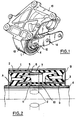
- FIG. 1 illustrates the overall arrangement of the device used as an elastic support for a powertrain.
- An external rigid tube (1) generally metallic, intended to be force-fitted - for example during the preparation operation, outside the production line - into the bore of a fastening element (13) integral of the casing (15) of the powertrain to be suspended, is assembled, by means of an elastic connection, on an internal rigid tube (4), generally metallic or made of plastic material, thick enough to admit the tightening of a through bolt (12), fixed by means of a connecting element (14) to the chassis, as shown, or else axially clamped in a yoke playing the same role.
- Figure 2 is an axial section on a vertical plane showing the components of the device in place.
- the external rigid tube (1), intended for fitting into the bore of the hanging machine, and the second intermediate rigid tube (3), concentric, are bonded, during the vulcanization operation, by methods well known in the rubber processing industry, with the second elastic side wall (B).
- the first intermediate rigid tube (2) and the internal rigid tube (4) are likewise adhered to the first lateral elastic wall (A), opposite, the internal rigid tube (4) being intended for fixing, by a yoke. or by a cantilever bolt on the fixed frame.
- the first intermediate rigid tube (2) is fitted, locally, in a sealed manner, into the external rigid tube (1), either axially or by a radial shrinking machine, crushing, over at most half the length of said first intermediate rigid tube (2), a thin layer of elastomeric composition (5) to seal with the first lateral elastic wall (A).
- the first intermediate rigid tube (2) is constricted, over the part of its length which is not in contact with the thin layer of elastomeric composition (5), in a zone (6) of revolution, substantially in the median plane of all.
- the holes (8) must, however, be arranged on either side of the bosses in elastomeric composition formed by local protuberance of the first lateral elastic wall (A) and of the second lateral elastic wall (B) to close the two chambers , in a substantially horizontal plane, for the figure.
- the second intermediate rigid tube (3) is fitted, in a simultaneous operation, over the internal rigid tube (4), either axially or by the expansion of said internal rigid tube (4), by crushing a film of elastomeric composition (9 ) to ensure, in certain configurations of the device, a seal in the annular recess (10).
- Thin membranes (11), in elastomeric composition, are formed, in the simplest way, by filling with the elastomeric composition, during molding, of the gaps constituted by large windows drilled in the second intermediate rigid tube (3). . Therefore, the thin membranes (11) are integral parts of the second intermediate rigid tube (3) of which they constitute a geometric extension in the window areas.
- the annular recess (10), formed between the second intermediate rigid tube (3) and the internal rigid tube (4), contains air.
- a venting groove is formed locally in the film of elastomeric composition (9), crushed between the second intermediate rigid tube (3) and the internal rigid tube (4).
- damping liquid is trapped in the annular recess (10), during the simultaneous fitting operation carried out within the damping liquid according to a process called "underwater".
- the windows drilled in the second intermediate rigid tube (3) have the same dimension, the deformation of the thin membranes (11) which close them will be equal and opposite and, the volume of the annular recess (10) being substantially constant, the passage damping liquid which is confined there, from one window to another, will have a parasitic mass effect, analogous to that of the main column of damping liquid of the laminar channel (7). It will then be possible to play on these two different mass effects to block the relative rigidity of the device at two different frequencies, that is to say it will become possible to have a minimum of rigidity between the two resonances, in the range of races that it is desirable to control, according to the needs of the intended application.
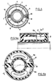
- Figure 3 is a half section, identical to Figure 2, but showing the components of the device before the fitting or shrinking operation carried out, for example, in "submarine", the constituent elements immersed in the liquid amortization.
- View 3a shows the first component, manufactured as an elastic joint of rubber / metal type, which consists of the first intermediate rigid tube (2), adhered via the first lateral elastic wall (A) to the internal rigid tube ( 4).
- this component will be defined, in the following, as the tubular assembly (2-A-4).
- the shape of the first lateral elastic wall (A) is shown, by way of nonlimiting example, of generally circular section, with the exception of bosses (20), located in the horizontal plane, to close the left half of the chambers. high and low enclosing the damping liquid.
- the first intermediate rigid tube (2) is covered, externally, and at least over the non-constricted length, with a thin layer of elastomeric composition (5) intended to ensure sealing.
- Said first rigid intermediate tube (2) is constricted in a zone (6) not in contact with the end of the first lateral elastic wall (A) to form a channel providing passage to the column of damping liquid.
- Two holes (8) located on either side of the horizontal plane, ensure, after having been rid of their burrs of elastomeric composition, the communication between the chambers and said column of damping liquid.
- the end (16) of the first intermediate rigid tube (2) which is used for fitting into the base of the second lateral elastic wall (B), adhered to the external rigid tube (1) will, advantageously, be chamfered, in this goal.
- View 3b shows the second component, also made as an elastic joint of rubber / metal type, which. consists of the external rigid tube (1), adhered through the second lateral elastic wall (B) to the second intermediate rigid tube (3).
- This second component will be defined, below, as the tubular assembly (1-B-3).
- the shape of the second lateral elastic wall (B) can be very similar to that of the first lateral elastic wall (A) and, as shown by way of nonlimiting example, of generally circular section, with the exception of bosses ( 20), located in the horizontal plane, to close the right half of the upper and lower chambers enclosing the damping liquid.
- bosses ( 20) located in the horizontal plane, to close the right half of the upper and lower chambers enclosing the damping liquid.
- the end (18) of the boss (20) of the second lateral elastic wall (B) comes into contact with the end (17) of the boss (20) carried by the first lateral elastic wall (A) .
- the second intermediate rigid tube (3) is coated, on a part of its internal face, with the film of elastomeric composition (9) intended, in certain configurations, to ensure sealing on the internal rigid tube (4). Its free end (19) being used for fitting over the area of the first lateral elastic wall (A) which is adhered to the internal rigid tube (4) will advantageously be chamfered for this purpose.
- the thin membranes (11) of the second intermediate rigid tube (3) are obtained by sealing with the elastomeric composition, during molding, the windows cut in the wall of said second intermediate rigid tube (3).
- View 3c shows the exterior of the internal rigid tube (4) and of the first intermediate rigid tube (2) with its narrowed zone (6) comprising the holes (8) for communication with the chambers containing the damping liquid.
- Figure 4 sectioned through the median plane of Figure 2 through the laminar channel (7), details the arrangement of communications between the chambers.
- FIG. 5 represents a variant of the elastic anti-vibration isolation device, where the communication between the chambers, provided by the holes (8) in FIG. 2, is produced by a groove (8a), formed in the second lateral elastic wall ( B), on either side of the boss end (18), molded with the second elastic side wall (B).
- View 5a shows the position of a sealed rivet (21) allowing, in a variant of the "submarine" mounting, the filling of the device by means of the vacuum created by the orifice subsequently closed by said rivet.
- View 5b is a section of the device through plane C of view 5a. Unlike Figure 4, this view does not cut the first rigid intermediate tube (2) which is only seen at the end, as is the first lateral elastic wall (A) which is illustrated a possibility of disposing of the cells in accordance with the section of FIG. 2. This view also shows the communication between the annular chambers filled with damping liquid, via the grooves (8a) beyond the boss end (18).
- the fitting force is exerted, then, by circular stops offset on the outer rim of each of the rigid tubes, at a speed adjusted so that an appropriate internal pressure is maintained by the inherent rigidity of the first lateral elastic wall (A) and the second lateral elastic wall (B).
- Another method uses, for the assembly, a machine for radial shrinking of the first intermediate rigid tube (2) and an expansion of the internal rigid tube (4).
- a variant of the method consists in applying a vacuum to the enclosure, prior to filling with the liquid intended to ensure the damping function, then in closing off the filling orifice with a sealed blind rivet such as that illustrated in (21 ) in Figure 5.
- This adaptability could be used to achieve, on a vehicle leaving the factory, a modification of the device allowing a harmonization of the mechanical characteristics of the suspension and of the tires, for example.
- the device with hydraulic damping of the radial elasticity is intended to provide the antivibration isolation of machines or vehicle engines.
Landscapes
- Engineering & Computer Science (AREA)
- General Engineering & Computer Science (AREA)
- Mechanical Engineering (AREA)
- Combined Devices Of Dampers And Springs (AREA)
- Springs (AREA)
- Insulators (AREA)
- Lubricants (AREA)
- Arrangement Or Mounting Of Propulsion Units For Vehicles (AREA)
- Supports For Pipes And Cables (AREA)
Claims (5)
Priority Applications (1)
| Application Number | Priority Date | Filing Date | Title |
|---|---|---|---|
| AT88400058T ATE53246T1 (de) | 1987-01-23 | 1988-01-13 | Schwingungsdaempfungsvorrichtung mit hydraulischer daempfung der radialen elastizitaet und verfahren zur herstellung einer derartigen vorrichtung. |
Applications Claiming Priority (2)
| Application Number | Priority Date | Filing Date | Title |
|---|---|---|---|
| FR8700762 | 1987-01-23 | ||
| FR8700762A FR2610055B1 (fr) | 1987-01-23 | 1987-01-23 | Dispositif d'isolation antivibratoire a amortissement hydraulique de l'elasticite radiale et procedes de realisation d'un tel dispositif |
Publications (2)
| Publication Number | Publication Date |
|---|---|
| EP0278801A1 EP0278801A1 (de) | 1988-08-17 |
| EP0278801B1 true EP0278801B1 (de) | 1990-05-30 |
Family
ID=9347188
Family Applications (1)
| Application Number | Title | Priority Date | Filing Date |
|---|---|---|---|
| EP88400058A Expired - Lifetime EP0278801B1 (de) | 1987-01-23 | 1988-01-13 | Schwingungsdämpfungsvorrichtung mit hydraulischer Dämpfung der radialen Elastizität und Verfahren zur Herstellung einer derartigen Vorrichtung |
Country Status (10)
| Country | Link |
|---|---|
| US (1) | US4893799A (de) |
| EP (1) | EP0278801B1 (de) |
| JP (1) | JPS63308244A (de) |
| AT (1) | ATE53246T1 (de) |
| BR (1) | BR8800199A (de) |
| CA (1) | CA1287826C (de) |
| DE (1) | DE3860189D1 (de) |
| ES (1) | ES2015336B3 (de) |
| FR (1) | FR2610055B1 (de) |
| GR (1) | GR3000611T3 (de) |
Families Citing this family (26)
| Publication number | Priority date | Publication date | Assignee | Title |
|---|---|---|---|---|
| US5044813A (en) * | 1988-01-26 | 1991-09-03 | The Goodyear Tire & Rubber Company | Bush type hydraulically damped engine or transmission mount |
| DE3827905A1 (de) * | 1988-08-17 | 1990-03-08 | Boge Ag | Hydraulisch daempfendes gummilager |
| JPH0650134B2 (ja) * | 1988-11-25 | 1994-06-29 | 鬼怒川ゴム工業株式会社 | 防振ゴムブッシュ |
| DE59005986D1 (de) * | 1989-03-25 | 1994-07-14 | Opel Adam Ag | Verspannbares, hydraulisch gedämpftes Lagerelement. |
| FR2645609B1 (fr) * | 1989-04-10 | 1994-04-01 | Caoutchouc Manufacture Plastique | Manchon elastique a amortissement hydraulique de l'elasticite radiale et decouplage en rigidite |
| JP2894497B2 (ja) * | 1989-05-15 | 1999-05-24 | 株式会社ブリヂストン | 防振装置 |
| US5221077A (en) * | 1989-05-15 | 1993-06-22 | Bridgestone Corporation | Vibration isolating apparatus |
| JPH0694889B2 (ja) * | 1989-06-15 | 1994-11-24 | 東海ゴム工業株式会社 | 流体封入式筒型マウント装置 |
| JPH0336541U (de) * | 1989-08-23 | 1991-04-09 | ||
| US5158269A (en) * | 1990-10-11 | 1992-10-27 | Gencorp Inc. | Dual/slipper shock mount |
| JPH0771513A (ja) * | 1993-09-03 | 1995-03-17 | Tokai Rubber Ind Ltd | 高粘性流体封入式筒型マウント |
| JP3477920B2 (ja) * | 1995-06-23 | 2003-12-10 | 東海ゴム工業株式会社 | 流体封入式防振支持体 |
| US6273406B1 (en) * | 1997-06-04 | 2001-08-14 | Honda Giken Kogyo Kabushiki Kaisha | Liquid-encapsulated bushing |
| GB2333573B (en) * | 1998-01-22 | 2001-10-03 | Draftex Ind Ltd | Vibration damping apparatus |
| JP2000074131A (ja) * | 1998-08-26 | 2000-03-07 | Honda Motor Co Ltd | 液体封入防振装置 |
| GB2342978B (en) * | 1998-10-22 | 2002-08-21 | Draftex Ind Ltd | Hydroelastic articulating joints |
| US20040016390A1 (en) * | 2002-07-29 | 2004-01-29 | Mcmillan Robert E. | Short-term indenting memory device and method |
| CA2511210A1 (en) * | 2004-07-14 | 2006-01-14 | The Pullman Company | Multi-direction tuned mass damper with unique assembly |
| US7644911B2 (en) * | 2005-09-22 | 2010-01-12 | The Pullman Company | Isolator |
| DE102005054852A1 (de) * | 2005-11-15 | 2007-05-24 | Zf Friedrichshafen Ag | Hydrolager und Verfahren zur Herstellung eines Hydrolagers |
| DE102007015239B4 (de) * | 2007-03-29 | 2012-03-29 | Trelleborg Automotive Germany Gmbh | Elastische Lagerbuchse |
| US7883071B2 (en) * | 2008-05-21 | 2011-02-08 | Raytheon Company | Methods and apparatus for isolation system |
| US8308149B2 (en) * | 2009-04-13 | 2012-11-13 | Hydro-Alre, Inc. | Shock and vibration isolation for aircraft brake control valve |
| JP6221954B2 (ja) | 2013-08-05 | 2017-11-01 | 東京エレクトロン株式会社 | 現像方法、現像装置及び記憶媒体 |
| US9360052B2 (en) | 2014-02-04 | 2016-06-07 | Innovation First, Inc. | Shaft collar |
| US9618077B2 (en) | 2015-07-23 | 2017-04-11 | Honeywell International Inc. | Isolators including main spring linear guide systems |
Family Cites Families (21)
| Publication number | Priority date | Publication date | Assignee | Title |
|---|---|---|---|---|
| FR2335744A1 (fr) * | 1975-12-15 | 1977-07-15 | Citroen Sa | Assemblage elastique a rigidite differentielle |
| DE2841505C2 (de) * | 1978-09-23 | 1983-04-07 | Boge Gmbh, 5208 Eitorf | Hydraulisch dämpfendes Gummilager |
| JPS5570636U (de) * | 1978-11-09 | 1980-05-15 | ||
| FR2462618A2 (fr) * | 1979-08-03 | 1981-02-13 | Peugeot | Cale elastique, notamment pour la suspension d'un moteur de vehicule |
| FR2443615A1 (fr) * | 1978-12-07 | 1980-07-04 | Peugeot | Cale elastique, notamment pour la suspension d'un moteur de vehicule |
| FR2467724A1 (fr) * | 1979-10-22 | 1981-04-30 | Peugeot | Cale elastique, notamment pour la suspension d'un moteur de vehicule |
| DE3028631C2 (de) * | 1980-07-29 | 1984-02-09 | Boge Gmbh, 5208 Eitorf | Axial belastbare Hülsengummifeder |
| JPS5794146A (en) * | 1980-12-02 | 1982-06-11 | Kinugawa Rubber Ind Co Ltd | Manufacture of bushing type anti-vibration device supporter |
| JPS5794147A (en) * | 1980-12-03 | 1982-06-11 | Kinugawa Rubber Ind Co Ltd | Manufacturing of bush-type vibro-isolating supporter |
| DE3046419A1 (de) * | 1980-12-10 | 1982-07-29 | Volkswagenwerk Ag, 3180 Wolfsburg | "daempfendes lager, insbesondere fuer eine fahrzeug-brennkraftmaschine" |
| JPS58203242A (ja) * | 1982-05-22 | 1983-11-26 | Tokai Rubber Ind Ltd | サスペンシヨンブツシユ並びにその製造法 |
| JPS6034542A (ja) * | 1983-08-05 | 1985-02-22 | Bridgestone Corp | 防振装置の製造方法 |
| DE3330462C2 (de) * | 1983-08-24 | 1986-11-06 | Fa. Carl Freudenberg, 6940 Weinheim | Hydraulisch bedämpftes Motorlager |
| JPS6049147A (ja) * | 1983-08-27 | 1985-03-18 | Tokai Rubber Ind Ltd | 流体入りブッシュ |
| JPS60184740A (ja) * | 1984-03-01 | 1985-09-20 | Kurashiki Kako Kk | 弾性ブツシユ |
| DE3519016A1 (de) * | 1985-05-25 | 1986-12-04 | Boge Gmbh, 5208 Eitorf | Axial belastbares lager |
| JP2583212B2 (ja) * | 1985-05-27 | 1997-02-19 | 日産自動車株式会社 | 振動減衰装置 |
| DE3531182A1 (de) * | 1985-08-31 | 1987-03-12 | Porsche Ag | Hydraulisch daempfendes lager |
| JPS6288834A (ja) * | 1985-10-15 | 1987-04-23 | Bridgestone Corp | 防振装置 |
| JPH06103056B2 (ja) * | 1985-11-25 | 1994-12-14 | 日産自動車株式会社 | 防振装置 |
| FR2595426B2 (fr) * | 1986-01-22 | 1989-09-15 | Peugeot | Articulation hydro-elastique |
-
1987
- 1987-01-23 FR FR8700762A patent/FR2610055B1/fr not_active Expired - Lifetime
-
1988
- 1988-01-13 AT AT88400058T patent/ATE53246T1/de not_active IP Right Cessation
- 1988-01-13 DE DE8888400058T patent/DE3860189D1/de not_active Expired - Lifetime
- 1988-01-13 EP EP88400058A patent/EP0278801B1/de not_active Expired - Lifetime
- 1988-01-13 ES ES88400058T patent/ES2015336B3/es not_active Expired - Lifetime
- 1988-01-21 BR BR8800199A patent/BR8800199A/pt not_active IP Right Cessation
- 1988-01-22 JP JP63012453A patent/JPS63308244A/ja active Pending
- 1988-01-22 CA CA000557209A patent/CA1287826C/fr not_active Expired - Lifetime
- 1988-01-22 US US07/147,296 patent/US4893799A/en not_active Expired - Fee Related
-
1990
- 1990-06-29 GR GR89400317T patent/GR3000611T3/el unknown
Also Published As
| Publication number | Publication date |
|---|---|
| FR2610055B1 (fr) | 1991-07-19 |
| DE3860189D1 (de) | 1990-07-05 |
| US4893799A (en) | 1990-01-16 |
| GR3000611T3 (en) | 1991-09-27 |
| ES2015336B3 (es) | 1990-08-16 |
| EP0278801A1 (de) | 1988-08-17 |
| JPS63308244A (ja) | 1988-12-15 |
| ATE53246T1 (de) | 1990-06-15 |
| CA1287826C (fr) | 1991-08-20 |
| FR2610055A1 (fr) | 1988-07-29 |
| BR8800199A (pt) | 1989-09-05 |
Similar Documents
| Publication | Publication Date | Title |
|---|---|---|
| EP0278801B1 (de) | Schwingungsdämpfungsvorrichtung mit hydraulischer Dämpfung der radialen Elastizität und Verfahren zur Herstellung einer derartigen Vorrichtung | |
| CA1310312C (fr) | Support elastique a amortissement hydraulique integre avec cloison rigidea circuit de liquide ajustable | |
| FR2486183A1 (fr) | Support amortisseur pour la suspension d'un corps oscillant a une structure de support | |
| FR2670552A1 (fr) | Attache hydroelastique de suspension et biellette de liaison geometrique liee a cette attache. | |
| FR2461165A1 (fr) | Monture d'amortissement de chocs | |
| CA1302441C (fr) | Dispositif elastique d'isolation antivibratoire a amortissement hydraulique integre et butees de limitation de debattements internes | |
| FR2601740A1 (fr) | Manchonnage elastique a remplissage de fluide | |
| FR2896842A1 (fr) | Support antivibratoire hydraulique et son procede de fabrication | |
| EP0910769B1 (de) | Schwingungsdampfer für kraftfahrzeugkupplungsausrückpedal | |
| FR2626947A1 (fr) | Manchonnage elastique a remplissage de fluide comportant un corps elastique pre-comprime radialement vers l'interieur | |
| EP0236161B1 (de) | Hydro-elastisches Lager mit zentraler Aufhängung, insbesondere für die Aufhängung eines Fahrzeugmotors | |
| EP0255434A1 (de) | Hydraulische Dämpfungslager | |
| EP0287455A1 (de) | Hydroelastisches Lager, insbesondere für Aufhängung eines Fahrzeugmotors | |
| EP1645773B1 (de) | Hydraulisches schwingungsdämpfendes Lager für ein Kraftfahrzeug und Herstellungsverfahren einer solchen Vorrichtung | |
| EP0392909B1 (de) | Elastische, hydraulisch gedämpfte Buchse mit radialer Elastizität und Entkoppelung der Steifigkeiten | |
| FR2973463A1 (fr) | Dispositif d'amortissement de vibration rempli de fluide du type a amortissement de vibration multidirectionnel | |
| FR2730537A1 (fr) | Manchon antivibratoire hydraulique et son procede de fabrication | |
| FR2655113A1 (fr) | Dispositif d'amortissement en elastomere rempli d'un fluide. | |
| FR2832477A1 (fr) | Cale hydroelastique | |
| FR2739668A1 (fr) | Dispositif perfectionne d'obturation a guide centreur lubrifie pour tube d'amortisseur hydraulique pressurise | |
| FR2578612A1 (fr) | Support d'absorption de vibrations | |
| EP0957286A1 (de) | Hydroelastisches Lager für die Lagerung einer Antriebseinheit in einer Fahrzeugkarosserie | |
| JPS63130944A (ja) | 粘性流体封入式ブツシユの製作方法 | |
| FR2662773A1 (fr) | Support rempli par un fluide et comportant une gorge a orifice menagee dans un corps elastique le long d'une decoupe menagee dans un manchon intermediaire du support. | |
| FR2814521A1 (fr) | Articulation hydroelastique a comportement dynamique haute frequence |
Legal Events
| Date | Code | Title | Description |
|---|---|---|---|
| PUAI | Public reference made under article 153(3) epc to a published international application that has entered the european phase |
Free format text: ORIGINAL CODE: 0009012 |
|
| AK | Designated contracting states |
Kind code of ref document: A1 Designated state(s): AT BE DE ES FR GB GR IT LU NL SE |
|
| 17P | Request for examination filed |
Effective date: 19880909 |
|
| 17Q | First examination report despatched |
Effective date: 19890519 |
|
| GRAA | (expected) grant |
Free format text: ORIGINAL CODE: 0009210 |
|
| AK | Designated contracting states |
Kind code of ref document: B1 Designated state(s): AT BE DE ES FR GB GR IT LU NL SE |
|
| REF | Corresponds to: |
Ref document number: 53246 Country of ref document: AT Date of ref document: 19900615 Kind code of ref document: T |
|
| ITF | It: translation for a ep patent filed | ||
| REF | Corresponds to: |
Ref document number: 3860189 Country of ref document: DE Date of ref document: 19900705 |
|
| GBT | Gb: translation of ep patent filed (gb section 77(6)(a)/1977) | ||
| REG | Reference to a national code |
Ref country code: GR Ref legal event code: FG4A Free format text: 3000611 |
|
| PLBE | No opposition filed within time limit |
Free format text: ORIGINAL CODE: 0009261 |
|
| STAA | Information on the status of an ep patent application or granted ep patent |
Free format text: STATUS: NO OPPOSITION FILED WITHIN TIME LIMIT |
|
| 26N | No opposition filed | ||
| REG | Reference to a national code |
Ref country code: GB Ref legal event code: 711G |
|
| PGFP | Annual fee paid to national office [announced via postgrant information from national office to epo] |
Ref country code: BE Payment date: 19921127 Year of fee payment: 6 |
|
| PGFP | Annual fee paid to national office [announced via postgrant information from national office to epo] |
Ref country code: AT Payment date: 19921207 Year of fee payment: 6 |
|
| PGFP | Annual fee paid to national office [announced via postgrant information from national office to epo] |
Ref country code: LU Payment date: 19921209 Year of fee payment: 6 |
|
| PGFP | Annual fee paid to national office [announced via postgrant information from national office to epo] |
Ref country code: SE Payment date: 19921214 Year of fee payment: 6 |
|
| PGFP | Annual fee paid to national office [announced via postgrant information from national office to epo] |
Ref country code: GB Payment date: 19930104 Year of fee payment: 6 |
|
| PGFP | Annual fee paid to national office [announced via postgrant information from national office to epo] |
Ref country code: ES Payment date: 19930114 Year of fee payment: 6 |
|
| PGFP | Annual fee paid to national office [announced via postgrant information from national office to epo] |
Ref country code: FR Payment date: 19930121 Year of fee payment: 6 |
|
| ITTA | It: last paid annual fee | ||
| PGFP | Annual fee paid to national office [announced via postgrant information from national office to epo] |
Ref country code: NL Payment date: 19930131 Year of fee payment: 6 |
|
| EPTA | Lu: last paid annual fee | ||
| PGFP | Annual fee paid to national office [announced via postgrant information from national office to epo] |
Ref country code: DE Payment date: 19930331 Year of fee payment: 6 |
|
| PG25 | Lapsed in a contracting state [announced via postgrant information from national office to epo] |
Ref country code: LU Free format text: LAPSE BECAUSE OF NON-PAYMENT OF DUE FEES Effective date: 19940113 Ref country code: GB Effective date: 19940113 Ref country code: AT Effective date: 19940113 |
|
| PG25 | Lapsed in a contracting state [announced via postgrant information from national office to epo] |
Ref country code: SE Effective date: 19940114 Ref country code: ES Free format text: LAPSE BECAUSE OF NON-PAYMENT OF DUE FEES Effective date: 19940114 |
|
| PG25 | Lapsed in a contracting state [announced via postgrant information from national office to epo] |
Ref country code: BE Effective date: 19940131 |
|
| PGFP | Annual fee paid to national office [announced via postgrant information from national office to epo] |
Ref country code: GR Payment date: 19940610 Year of fee payment: 7 |
|
| BERE | Be: lapsed |
Owner name: CAOUTCHOUC MANUFACTURE ET PLASTIQUES Effective date: 19940131 |
|
| PG25 | Lapsed in a contracting state [announced via postgrant information from national office to epo] |
Ref country code: NL Effective date: 19940801 |
|
| GBPC | Gb: european patent ceased through non-payment of renewal fee |
Effective date: 19940113 |
|
| NLV4 | Nl: lapsed or anulled due to non-payment of the annual fee | ||
| PG25 | Lapsed in a contracting state [announced via postgrant information from national office to epo] |
Ref country code: FR Effective date: 19940930 |
|
| PG25 | Lapsed in a contracting state [announced via postgrant information from national office to epo] |
Ref country code: DE Effective date: 19941001 |
|
| REG | Reference to a national code |
Ref country code: FR Ref legal event code: ST |
|
| EUG | Se: european patent has lapsed |
Ref document number: 88400058.9 Effective date: 19940810 |
|
| PG25 | Lapsed in a contracting state [announced via postgrant information from national office to epo] |
Ref country code: GR Free format text: THE PATENT HAS BEEN ANNULLED BY A DECISION OF A NATIONAL AUTHORITY Effective date: 19950731 |
|
| REG | Reference to a national code |
Ref country code: GR Ref legal event code: MM2A Free format text: 3000611 |
|
| REG | Reference to a national code |
Ref country code: ES Ref legal event code: FD2A Effective date: 19990405 |
|
| PG25 | Lapsed in a contracting state [announced via postgrant information from national office to epo] |
Ref country code: IT Free format text: LAPSE BECAUSE OF NON-PAYMENT OF DUE FEES;WARNING: LAPSES OF ITALIAN PATENTS WITH EFFECTIVE DATE BEFORE 2007 MAY HAVE OCCURRED AT ANY TIME BEFORE 2007. THE CORRECT EFFECTIVE DATE MAY BE DIFFERENT FROM THE ONE RECORDED. Effective date: 20050113 |