EP0277255A1 - Poutrelle composite - Google Patents
Poutrelle composite Download PDFInfo
- Publication number
- EP0277255A1 EP0277255A1 EP87101536A EP87101536A EP0277255A1 EP 0277255 A1 EP0277255 A1 EP 0277255A1 EP 87101536 A EP87101536 A EP 87101536A EP 87101536 A EP87101536 A EP 87101536A EP 0277255 A1 EP0277255 A1 EP 0277255A1
- Authority
- EP
- European Patent Office
- Prior art keywords
- trimmed
- carrier according
- logs
- stampings
- nail
- Prior art date
- Legal status (The legal status is an assumption and is not a legal conclusion. Google has not performed a legal analysis and makes no representation as to the accuracy of the status listed.)
- Withdrawn
Links
- 239000002131 composite material Substances 0.000 title claims abstract description 32
- 230000003068 static effect Effects 0.000 claims abstract description 4
- 230000015572 biosynthetic process Effects 0.000 claims description 5
- 238000004080 punching Methods 0.000 claims description 5
- 230000000630 rising effect Effects 0.000 claims description 3
- 210000001503 joint Anatomy 0.000 description 5
- 238000004519 manufacturing process Methods 0.000 description 5
- 230000001070 adhesive effect Effects 0.000 description 4
- 238000010276 construction Methods 0.000 description 2
- 230000007774 longterm Effects 0.000 description 2
- 235000014277 Clidemia hirta Nutrition 0.000 description 1
- 241000069219 Henriettea Species 0.000 description 1
- 230000007423 decrease Effects 0.000 description 1
- 230000000694 effects Effects 0.000 description 1
- 230000007794 irritation Effects 0.000 description 1
- 239000002184 metal Substances 0.000 description 1
- 238000009966 trimming Methods 0.000 description 1
- 239000002916 wood waste Substances 0.000 description 1
Images


Classifications
-
- F—MECHANICAL ENGINEERING; LIGHTING; HEATING; WEAPONS; BLASTING
- F16—ENGINEERING ELEMENTS AND UNITS; GENERAL MEASURES FOR PRODUCING AND MAINTAINING EFFECTIVE FUNCTIONING OF MACHINES OR INSTALLATIONS; THERMAL INSULATION IN GENERAL
- F16B—DEVICES FOR FASTENING OR SECURING CONSTRUCTIONAL ELEMENTS OR MACHINE PARTS TOGETHER, e.g. NAILS, BOLTS, CIRCLIPS, CLAMPS, CLIPS OR WEDGES; JOINTS OR JOINTING
- F16B15/00—Nails; Staples
- F16B15/0023—Nail plates
- F16B15/003—Nail plates with teeth cut out from the material of the plate
- F16B15/0046—Nail plates with teeth cut out from the material of the plate from the body of the plate
-
- E—FIXED CONSTRUCTIONS
- E04—BUILDING
- E04C—STRUCTURAL ELEMENTS; BUILDING MATERIALS
- E04C3/00—Structural elongated elements designed for load-supporting
- E04C3/02—Joists; Girders, trusses, or trusslike structures, e.g. prefabricated; Lintels; Transoms; Braces
- E04C3/12—Joists; Girders, trusses, or trusslike structures, e.g. prefabricated; Lintels; Transoms; Braces of wood, e.g. with reinforcements, with tensioning members
- E04C3/14—Joists; Girders, trusses, or trusslike structures, e.g. prefabricated; Lintels; Transoms; Braces of wood, e.g. with reinforcements, with tensioning members with substantially solid, i.e. unapertured, web
-
- E—FIXED CONSTRUCTIONS
- E04—BUILDING
- E04C—STRUCTURAL ELEMENTS; BUILDING MATERIALS
- E04C3/00—Structural elongated elements designed for load-supporting
- E04C3/02—Joists; Girders, trusses, or trusslike structures, e.g. prefabricated; Lintels; Transoms; Braces
- E04C3/12—Joists; Girders, trusses, or trusslike structures, e.g. prefabricated; Lintels; Transoms; Braces of wood, e.g. with reinforcements, with tensioning members
- E04C3/17—Joists; Girders, trusses, or trusslike structures, e.g. prefabricated; Lintels; Transoms; Braces of wood, e.g. with reinforcements, with tensioning members with non-parallel upper and lower edges, e.g. roof trusses
-
- E—FIXED CONSTRUCTIONS
- E04—BUILDING
- E04C—STRUCTURAL ELEMENTS; BUILDING MATERIALS
- E04C3/00—Structural elongated elements designed for load-supporting
- E04C3/02—Joists; Girders, trusses, or trusslike structures, e.g. prefabricated; Lintels; Transoms; Braces
- E04C3/12—Joists; Girders, trusses, or trusslike structures, e.g. prefabricated; Lintels; Transoms; Braces of wood, e.g. with reinforcements, with tensioning members
- E04C3/18—Joists; Girders, trusses, or trusslike structures, e.g. prefabricated; Lintels; Transoms; Braces of wood, e.g. with reinforcements, with tensioning members with metal or other reinforcements or tensioning members
-
- E—FIXED CONSTRUCTIONS
- E04—BUILDING
- E04C—STRUCTURAL ELEMENTS; BUILDING MATERIALS
- E04C3/00—Structural elongated elements designed for load-supporting
- E04C3/38—Arched girders or portal frames
- E04C3/42—Arched girders or portal frames of wood, e.g. units for rafter roofs
-
- Y—GENERAL TAGGING OF NEW TECHNOLOGICAL DEVELOPMENTS; GENERAL TAGGING OF CROSS-SECTIONAL TECHNOLOGIES SPANNING OVER SEVERAL SECTIONS OF THE IPC; TECHNICAL SUBJECTS COVERED BY FORMER USPC CROSS-REFERENCE ART COLLECTIONS [XRACs] AND DIGESTS
- Y10—TECHNICAL SUBJECTS COVERED BY FORMER USPC
- Y10S—TECHNICAL SUBJECTS COVERED BY FORMER USPC CROSS-REFERENCE ART COLLECTIONS [XRACs] AND DIGESTS
- Y10S52/00—Static structures, e.g. buildings
- Y10S52/06—Toothed connecting means
Definitions
- the invention relates to composite beams, at least partially consisting of trimmed logs, which are connected by means of nail plates.
- the known composite beams of this type are composed of rectangular or square prismatic beams that are trimmed on all sides.
- the manufacture of these beams is based on the smaller diameter at the end of the braid of a log, which, depending on the length of the beam to be created, results in relatively large sections at the foot end, which result in a loss of a stable cross-section.
- the diameter per linear meter increases or decreases by 1 cm, so that a tree trunk, for example 10 m long, has a diameter difference of about 10 cm between the end of the foot and the braid.
- connection of the beams with the known nail plates has also proven to be room for improvement. It has been found that with vibrating loads and peak loads, the nails loosen and the load-bearing capacity of the composite beam is reduced.
- the object of the present invention is to provide composite girders which at least partially consist of logs which are lined in accordance with the consistent course of logs and are associated with one another in accordance with the static requirements with the same or opposite conicity and which have a particularly high load-bearing capacity and long-term durability .
- logs are trimmed according to the conical shape of wooden trunks and are connected to one another according to the static requirements with rectified or oppositely directed conicity by means of nail plates, which are made of tongue-shaped stampings which are arranged parallel to the longitudinal edges of the nail plate , Has formed nails, and the front edge and / or rear edge is formed like a step.
- the invention has the advantage that it enables particularly cost-effective production of particularly load-bearing composite beams.
- the advantage of the particularly high and also particularly long-term load-bearing capacity is achieved by using the specially designed nail plate.
- the base rows of the nails do not run parallel to the grain of the bars to be connected to one another by the nail plate. If this nail plate z. B. with their lateral edges arranged approximately parallel to the butt joint of two beams to be joined together, both the rows of nail base points, which are arranged transversely on the nail plate, and the rows of nail base points, which are arranged parallel to the long sides of the nail plate , diagonally to the butt joint of the beams to be connected.
- the wide flat side of the individual flat nails also runs diagonally to the butt joint. This increases the adhesion of the row of nails and considerably reduces the risk of loosening the connection in the case of vibrating loads and in the case of peak irritation.
- the composite carrier consists of round timbers, which are trimmed on four sides to form truncated pyramid-shaped round timbers with a rectangular or square cross-section and are connected to one another with their tapered ends, ie in the same direction.
- the composite carrier consists of round timbers, which are trimmed on the sides designated as contact surfaces in accordance with the conical shape of the logs, but are trimmed on the sides receiving the nail plates to form parallel curses, the round timbers with oppositely directed ones Taper, that is connected to each other with the pigtail end lying on the foot end.
- the composite beam can consist of conically trimmed logs, which are connected to a rectangular or square cross-section with prismatic beams, the width of which is chosen to be equal to the distance between the parallel surfaces of the logs.
- the front edge and the rear edge of the nail plate can go from one side edge to the other side edge be designed in the same direction as rising or falling steps.
- This form of training has the advantage that the nail plate is approximately rhombus-shaped in its outer circumference, as a result of which the associated advantages are achieved.
- the steps of the front edge of the nail plate are formed relative to one another in each case at the same intervals as the steps of the rear edge relative to one another.
- This form of embodiment of the invention has the advantage, on the one hand, that the nail plates can be produced inexpensively because the step-like cuts can each be carried out with the same tool.
- these nail plates if it is expedient or even necessary, can be arranged directly next to one another, without a gap between them.
- laterally adjacent stampings are each oriented in opposite directions. This further development has the advantage that the nail plate itself maintains maximum stability.
- the base points are expediently at a distance from the base points of the nails of a row of nails extending transversely from one side edge to the other, from the base points of the counter-shaped base plates arranged between them, which is greater than the length of the base plates.
- This form of education of the invention also contributes to that maximum stability of the nail plate is maintained.
- the nail plate can consist of relatively thin sheet metal, which in turn keeps the cost of the nail plate low.
- the distances between the rows of punchings aligned in the same direction can each be the same size.
- the base points of a row of stampings each lie between two rows of base points of counter-aligned stampings.
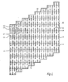
- a log (3) is illustrated, from which logs (1) are formed by trimming on four sides according to its conical shape.
- Such logs which therefore have a truncated pyramid shape, can be connected to a carrier unit by means of nail plates (2) according to FIG.
- the composite carrier has the same cross-sectional shape, the round timbers (1) with the opposite tapering end having the tapered, tapered end lying on the foot end, on the conical contact surfaces (4), through the nail plates (10) connected with each other. Those surfaces (5) that receive the nail plates (10) are trimmed parallel to each other, which results in the rectangular cross section.
- FIG. 4 shows a composite carrier with omission of the nail plates (10), which is formed from round timbers (1), which, as shown in FIG. 3, are arranged with the tapered ends opposite to the pigtail.
- a bar (6) with a rectangular or square cross-section is arranged between these logs (1). The width of this bar (6) corresponds to the distance between the surfaces of the logs (1) lying parallel to one another.
- FIG. 5 shows, again with the nail plates (10) omitted, a top view of a composite carrier according to FIGS. 3 and 4.
- FIG. 6 shows a plan view of a nail plate 10 according to the invention.
- the punchings 12 are aligned and bent parallel to the longitudinal edges 16 and 18 of the plate 10 so that they form nails. Alternately, a row of punchings is always aligned in one sense, parallel to the side edges 16 and 18, and the next row of diecuts in the direction of the side edges is aligned in opposite directions.
- These die cuts are arranged so that the tips 20 of a series of die cuts extend between two opposing die cuts. However, the distance between the base points 24 of the one row of die cuts is so far from the base points 26 of the die cuts punched with it that the tips 20 are each arranged on a transverse row which extend between the base row of two nested rows. In this way, the area between two base points 24, 24 and 26, 26 is not interrupted by any punching. This ensures a particularly high stability of the nail plate.
- the front edge 30 and the rear edge 32 of the nail plate are stepped, rising from the bottom left to the top right.
- This embodiment of the invention brings about the desired effect that the nail plate 10 itself is approximately rhombus-shaped in its outer circumference.
- FIG. 7 shows a composite carrier which consists of two beams 34 and 36 which are connected to one another by the nail plates 10 according to the invention.
- the support wedges 38 show two supports on which the composite support rests with its two ends.
- the nail plates 10 according to the invention are nailed to the two beams in such a way that the stepped front and rear edges 30 and 32 of the nail plate are approximately parallel to the butt joint 33 between the two interconnected bars 34 and 36 are arranged.
- both the rows of nails, which extend parallel to the long side 16 or 18 of the nail plate 10 and the rows of nails, which run transversely to the nail plate, run obliquely to the butt joint 33.
- a particularly great adhesive effect is thereby achieved.
- the entire surface area of the nail plate 10 is available for attaching nails.
- the adhesive effect of the composite carrier is particularly great.
- FIG. 8 shows a roof beam construction comprising a carrier 40 and two gable beams 42 and two further inclined supports 44.
- the supports 40 and the gable blocks 42 are each connected to one another by nail plates 10 according to the present invention.
- the cross member 40 and the inclined supports 44 are each closely connected by nail plates 10 according to the invention.
- the nail plates 10 according to the invention can also be used together with other nail plates 46 for the production of composite structures.
- the present invention allows a variety of similar embodiments of the nail plate and a variety of advantageous applications that will occur to those skilled in the art from the above description. Such embodiments fall within the scope of the present invention.
Landscapes
- Engineering & Computer Science (AREA)
- Architecture (AREA)
- Civil Engineering (AREA)
- Structural Engineering (AREA)
- Life Sciences & Earth Sciences (AREA)
- Wood Science & Technology (AREA)
- General Engineering & Computer Science (AREA)
- Mechanical Engineering (AREA)
- Joining Of Building Structures In Genera (AREA)
Priority Applications (3)
| Application Number | Priority Date | Filing Date | Title |
|---|---|---|---|
| EP87101536A EP0277255A1 (fr) | 1987-02-05 | 1987-02-05 | Poutrelle composite |
| US07/152,479 US4833859A (en) | 1987-02-05 | 1988-02-05 | Composite beam |
| PL27048688A PL270486A1 (en) | 1987-02-05 | 1988-02-05 | Multipiece girder |
Applications Claiming Priority (1)
| Application Number | Priority Date | Filing Date | Title |
|---|---|---|---|
| EP87101536A EP0277255A1 (fr) | 1987-02-05 | 1987-02-05 | Poutrelle composite |
Publications (1)
| Publication Number | Publication Date |
|---|---|
| EP0277255A1 true EP0277255A1 (fr) | 1988-08-10 |
Family
ID=8196717
Family Applications (1)
| Application Number | Title | Priority Date | Filing Date |
|---|---|---|---|
| EP87101536A Withdrawn EP0277255A1 (fr) | 1987-02-05 | 1987-02-05 | Poutrelle composite |
Country Status (3)
| Country | Link |
|---|---|
| US (1) | US4833859A (fr) |
| EP (1) | EP0277255A1 (fr) |
| PL (1) | PL270486A1 (fr) |
Families Citing this family (7)
| Publication number | Priority date | Publication date | Assignee | Title |
|---|---|---|---|---|
| FI3491U1 (fi) * | 1997-12-05 | 1998-07-30 | Pentti Kalevi Pelkonen | Rakennuspalkki |
| US9719257B2 (en) | 2013-12-06 | 2017-08-01 | Jack Walters & Sons, Corp. | Friction fit composite column |
| US9234350B1 (en) | 2013-12-06 | 2016-01-12 | Jack Walters & Sons, Corp. | System and method of constructing a composite assembly |
| US9528265B1 (en) * | 2013-12-06 | 2016-12-27 | Jack Walters & Sons, Corp. | System and method of constructing a composite assembly |
| WO2017100178A1 (fr) | 2015-12-08 | 2017-06-15 | Jack Walters & Sons, Corp. | Colonne composite à ajustement par frottement |
| US10443240B2 (en) | 2017-10-02 | 2019-10-15 | Jack Walters & Son, Corp. | Reinforced composite column |
| DE102019106602A1 (de) * | 2019-03-15 | 2020-09-17 | Adolf Würth Gmbh & Co Kg | Reibplatte für eine Holzverbindung |
Citations (3)
| Publication number | Priority date | Publication date | Assignee | Title |
|---|---|---|---|---|
| FR962589A (fr) * | 1950-06-16 | |||
| US4510724A (en) * | 1981-10-13 | 1985-04-16 | Karl Magnuson | Building structure |
| EP0181854A2 (fr) * | 1984-10-29 | 1986-05-21 | Johann Wolf GmbH KG | Connecteur à griffes pour la fabrication de poutres composites |
Family Cites Families (8)
| Publication number | Priority date | Publication date | Assignee | Title |
|---|---|---|---|---|
| US705626A (en) * | 1902-03-17 | 1902-07-29 | Ernest H Vogel | Metallic strap. |
| US3016586A (en) * | 1959-10-06 | 1962-01-16 | Timber Truss Connectors Inc | Connector plate |
| DE1459885A1 (de) * | 1963-01-10 | 1969-05-08 | Automated Building Components | Metallisches Anschlussstueck zum Verbinden von hoelzernen Strukturgliedern und unter Verwendung eines solchen Stuecks hergestellte Verbindung |
| US3487866A (en) * | 1966-08-08 | 1970-01-06 | Runnion Ernest E | Production of lumber and pulp chips from small-diameter logs |
| US3494645A (en) * | 1968-05-06 | 1970-02-10 | Automated Building Components | High section splice plate and joint therewith |
| US4562683A (en) * | 1982-05-24 | 1986-01-07 | Gang-Nail Systems, Inc. | Hinged metal webs for truss structures |
| US4442649A (en) * | 1982-10-18 | 1984-04-17 | Robert Birckhead | Fabricated beam |
| US4476663A (en) * | 1983-08-15 | 1984-10-16 | Bikales Victor W | Structure with composite members |
-
1987
- 1987-02-05 EP EP87101536A patent/EP0277255A1/fr not_active Withdrawn
-
1988
- 1988-02-05 US US07/152,479 patent/US4833859A/en not_active Expired - Fee Related
- 1988-02-05 PL PL27048688A patent/PL270486A1/xx unknown
Patent Citations (3)
| Publication number | Priority date | Publication date | Assignee | Title |
|---|---|---|---|---|
| FR962589A (fr) * | 1950-06-16 | |||
| US4510724A (en) * | 1981-10-13 | 1985-04-16 | Karl Magnuson | Building structure |
| EP0181854A2 (fr) * | 1984-10-29 | 1986-05-21 | Johann Wolf GmbH KG | Connecteur à griffes pour la fabrication de poutres composites |
Non-Patent Citations (1)
| Title |
|---|
| FRICK/KNÖLL/NEUMANN "Baukonstruktionslehre Teil 1", 27. Auflage, 1983, Seite 79, B.G. Teubner, Stuttgart; * |
Also Published As
| Publication number | Publication date |
|---|---|
| US4833859A (en) | 1989-05-30 |
| PL270486A1 (en) | 1989-01-23 |
Similar Documents
| Publication | Publication Date | Title |
|---|---|---|
| EP2208835B1 (fr) | Panneau, en particulier panneau de sol | |
| EP0131841B1 (fr) | Ancrage pour un panneau stratifié | |
| DE1291882B (de) | Krallenplatte zum Verbinden von Holzstaeben | |
| DE19718319A1 (de) | Parkettelement | |
| EP0181854B1 (fr) | Connecteur à griffes pour la fabrication de poutres composites | |
| DE1400753B2 (fr) | ||
| DE2206973C3 (de) | Räumliches Bauelement zur Bildung von Trag- und Stützwerken | |
| EP0277255A1 (fr) | Poutrelle composite | |
| EP0332061B1 (fr) | Plate-forme d'échafaudage | |
| EP0277256A1 (fr) | Connecteur à griffes | |
| DE2727575A1 (de) | Metallgitterrost sowie verfahren und vorrichtung zu seiner herstellung | |
| DE2908335A1 (de) | Verfahren und vorrichtung zum gleichzeitigen ausschneiden von mindestens drei kammartig zusammenhaengenden teilen aus einem blechband | |
| DE3335702A1 (de) | Aus einem stahlblechstreifen geformtes befestigungselement wie nagel od. dgl. | |
| DE2613522C3 (de) | Für Holzverbindungen bestimmte Krallenplatte | |
| DE602004010196T2 (de) | Baurahmenprofil | |
| EP0625438B1 (fr) | Maillon à étai pour chaînes de pneu | |
| DE2646432C2 (de) | Verbindung eines Balkens mit einem Stützbalken | |
| CH328681A (de) | Holzbalken | |
| EP0384015B1 (fr) | Caillebottis métallique | |
| DE1945239A1 (de) | Wandelement | |
| DE102006018089A1 (de) | Verbundanker basiertes Tragwerk | |
| DE19548334A1 (de) | Holzverbinder | |
| DE3210928A1 (de) | I-foermiger leichtbautraeger | |
| DE844813C (de) | Hoelzerner Gittertraeger oder Gittermast | |
| DE1297316B (de) | Krallenplatte zum Verbinden von Bauteilen aus Holz |
Legal Events
| Date | Code | Title | Description |
|---|---|---|---|
| PUAI | Public reference made under article 153(3) epc to a published international application that has entered the european phase |
Free format text: ORIGINAL CODE: 0009012 |
|
| AK | Designated contracting states |
Kind code of ref document: A1 Designated state(s): AT DE FR GB IT SE |
|
| 17P | Request for examination filed |
Effective date: 19881021 |
|
| 17Q | First examination report despatched |
Effective date: 19891205 |
|
| STAA | Information on the status of an ep patent application or granted ep patent |
Free format text: STATUS: THE APPLICATION IS DEEMED TO BE WITHDRAWN |
|
| 18D | Application deemed to be withdrawn |
Effective date: 19910829 |
|
| RIN1 | Information on inventor provided before grant (corrected) |
Inventor name: WOLF, JOHANN |