EP0275984A2 - Installation d'allumage capacitif, particulièrement pour petits moteurs, avec dispositif de retard - Google Patents
Installation d'allumage capacitif, particulièrement pour petits moteurs, avec dispositif de retard Download PDFInfo
- Publication number
- EP0275984A2 EP0275984A2 EP88100723A EP88100723A EP0275984A2 EP 0275984 A2 EP0275984 A2 EP 0275984A2 EP 88100723 A EP88100723 A EP 88100723A EP 88100723 A EP88100723 A EP 88100723A EP 0275984 A2 EP0275984 A2 EP 0275984A2
- Authority
- EP
- European Patent Office
- Prior art keywords
- capacitor
- charging
- ignition
- coil
- switch
- Prior art date
- Legal status (The legal status is an assumption and is not a legal conclusion. Google has not performed a legal analysis and makes no representation as to the accuracy of the status listed.)
- Granted
Links
Images
Classifications
-
- F—MECHANICAL ENGINEERING; LIGHTING; HEATING; WEAPONS; BLASTING
- F02—COMBUSTION ENGINES; HOT-GAS OR COMBUSTION-PRODUCT ENGINE PLANTS
- F02P—IGNITION, OTHER THAN COMPRESSION IGNITION, FOR INTERNAL-COMBUSTION ENGINES; TESTING OF IGNITION TIMING IN COMPRESSION-IGNITION ENGINES
- F02P5/00—Advancing or retarding ignition; Control therefor
- F02P5/04—Advancing or retarding ignition; Control therefor automatically, as a function of the working conditions of the engine or vehicle or of the atmospheric conditions
- F02P5/145—Advancing or retarding ignition; Control therefor automatically, as a function of the working conditions of the engine or vehicle or of the atmospheric conditions using electrical means
- F02P5/155—Analogue data processing
-
- F—MECHANICAL ENGINEERING; LIGHTING; HEATING; WEAPONS; BLASTING
- F02—COMBUSTION ENGINES; HOT-GAS OR COMBUSTION-PRODUCT ENGINE PLANTS
- F02P—IGNITION, OTHER THAN COMPRESSION IGNITION, FOR INTERNAL-COMBUSTION ENGINES; TESTING OF IGNITION TIMING IN COMPRESSION-IGNITION ENGINES
- F02P1/00—Installations having electric ignition energy generated by magneto- or dynamo- electric generators without subsequent storage
- F02P1/08—Layout of circuits
- F02P1/086—Layout of circuits for generating sparks by discharging a capacitor into a coil circuit
-
- F—MECHANICAL ENGINEERING; LIGHTING; HEATING; WEAPONS; BLASTING
- F02—COMBUSTION ENGINES; HOT-GAS OR COMBUSTION-PRODUCT ENGINE PLANTS
- F02P—IGNITION, OTHER THAN COMPRESSION IGNITION, FOR INTERNAL-COMBUSTION ENGINES; TESTING OF IGNITION TIMING IN COMPRESSION-IGNITION ENGINES
- F02P3/00—Other installations
- F02P3/06—Other installations having capacitive energy storage
- F02P3/08—Layout of circuits
- F02P3/0853—Layout of circuits for control of the dwell or anti-dwell time
- F02P3/0861—Closing the discharge circuit of the storage capacitor with semiconductor devices
-
- F—MECHANICAL ENGINEERING; LIGHTING; HEATING; WEAPONS; BLASTING
- F02—COMBUSTION ENGINES; HOT-GAS OR COMBUSTION-PRODUCT ENGINE PLANTS
- F02P—IGNITION, OTHER THAN COMPRESSION IGNITION, FOR INTERNAL-COMBUSTION ENGINES; TESTING OF IGNITION TIMING IN COMPRESSION-IGNITION ENGINES
- F02P5/00—Advancing or retarding ignition; Control therefor
- F02P5/04—Advancing or retarding ignition; Control therefor automatically, as a function of the working conditions of the engine or vehicle or of the atmospheric conditions
- F02P5/145—Advancing or retarding ignition; Control therefor automatically, as a function of the working conditions of the engine or vehicle or of the atmospheric conditions using electrical means
- F02P5/155—Analogue data processing
- F02P5/1558—Analogue data processing with special measures for starting
-
- F—MECHANICAL ENGINEERING; LIGHTING; HEATING; WEAPONS; BLASTING
- F02—COMBUSTION ENGINES; HOT-GAS OR COMBUSTION-PRODUCT ENGINE PLANTS
- F02P—IGNITION, OTHER THAN COMPRESSION IGNITION, FOR INTERNAL-COMBUSTION ENGINES; TESTING OF IGNITION TIMING IN COMPRESSION-IGNITION ENGINES
- F02P9/00—Electric spark ignition control, not otherwise provided for
- F02P9/002—Control of spark intensity, intensifying, lengthening, suppression
- F02P9/005—Control of spark intensity, intensifying, lengthening, suppression by weakening or suppression of sparks to limit the engine speed
-
- Y—GENERAL TAGGING OF NEW TECHNOLOGICAL DEVELOPMENTS; GENERAL TAGGING OF CROSS-SECTIONAL TECHNOLOGIES SPANNING OVER SEVERAL SECTIONS OF THE IPC; TECHNICAL SUBJECTS COVERED BY FORMER USPC CROSS-REFERENCE ART COLLECTIONS [XRACs] AND DIGESTS
- Y02—TECHNOLOGIES OR APPLICATIONS FOR MITIGATION OR ADAPTATION AGAINST CLIMATE CHANGE
- Y02T—CLIMATE CHANGE MITIGATION TECHNOLOGIES RELATED TO TRANSPORTATION
- Y02T10/00—Road transport of goods or passengers
- Y02T10/10—Internal combustion engine [ICE] based vehicles
- Y02T10/40—Engine management systems
Definitions
- the invention relates to a capacitor ignition system for small gasoline engines with a charging capacitor arranged in the primary circuit of the ignition coil, a charging coil in which the permanent magnet of a magnet wheel induces the charging voltage and with an electronic ignition switch discharging the charging capacitor via the primary winding of the ignition coil, in particular a thyristor, the of which a trigger circuit controlled control circuit - to achieve a late adjustment - is bridged by a second capacitor in series with a late adjustment switch which can be controlled via a delay capacitor connected in parallel with a charging coil, to which a limiting resistor is connected in parallel.
- Condenser ignition systems have been known for many years. They are characterized by a very simple, robust structure. When the permanent magnet of the magnet wheel moves past, a voltage is first induced in the charging coil, which charges the charging capacitor via a diode. Via trigger circuits of different configurations, the charging capacitor is discharged via the primary winding of the ignition coil at a desired point in time after the charging capacitor has been fully charged, and the desired ignition pulse is thus induced in the secondary winding.
- capacitor ignition systems with external triggering already exist, in which a corresponding adjustment of the ignition timing is possible via complex electronics.
- these ignition systems are extremely complicated due to the necessary delay electronics, so that they cannot be used, in particular for small petrol engines, for economic reasons alone.
- the invention is therefore based on the object of designing a capacitor ignition system of the type mentioned at the outset in such a way that the use of a separate coil is avoided with an even greater late adjustment range.
- the trigger circuit contains a separate charging capacitor lying parallel to the charging coil and a parallel discharge branch made of resistors and a blocking switch, preferably in the form of a transistor, with a tap arranged between them for the control electrode of the ignition switch, the blocking switch during the charging phase of the Charging capacitor is turned on.
- the trigger circuit controls the actual ignition switch and, as a result, discharges the charging capacitor at the end of the charging voltage half-wave.
- the switching of the coils is preferably carried out in such a way that the ignition takes place at the end of the second (strongest) voltage half-wave of the three half-waves induced by the magnet wheel with each revolution in each coil.
- the control electrode of the ignition switch is connected to ground via the cut-off switch, so that ignition is impossible.
- a blocking capacitor that reliably switches the blocking switch beyond the end of the charging half-wave is provided - does the transition of the blocking capacitor into the blocking position make it possible to discharge the separate charging capacitor via the control path of the ignition switch and thus to switch it through.
- control electrode of the blocking switch is connected to the charging coil of the charging capacitor via a resistor.
- trigger-lock control of the lock switch can additionally be provided via a transistor actuated by the pole wheel charging pulse in the primary winding of the ignition coil on the control circuit of the lock switch.
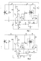
- a rotating permanent magnet M of a magnet wheel generates three voltage half-waves in each of the coils sitting on an iron core, the charging coil L1, the primary winding L2 and the secondary winding L3 of the ignition coil.
- the charging coil L1 is connected so that the strongest, namely the second voltage half-wave, generates a positive voltage at output A.
- the transistor T1 forming a blocking switch is turned on via the resistor R7, and thereby the gate of the actual ignition switch of the thyristor Thy 1 is kept at ground.
- the thyristor Thy 1 is ignited and the charging capacitor C3 discharges through the primary winding L2 of the ignition coil. An ignition spark is generated on the secondary side of the ignition coil.
- a particular advantage of the capacitor ignition system according to FIG. 1 described above is that no additional coils are required and that in particular the speed-dependent voltage is tapped directly at the primary coil of the ignition coil via a diode D6. Furthermore, it is particularly favorable to arrange the coils so that the ignition at the end of the second voltage half-wave, i.e. the strongest of the half-waves induced by the magnet wheel.
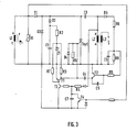
- FIG. 2 A modification of the circuit according to FIG. 1 using this triggering by the primary coil of the ignition coil is shown in FIG. 2.
- the resistor R7 which has switched on the transistor T1 forming the blocking circuit during the charging of the charging capacitor C3 and thereby prevented ignition, is connected to the cathode of the tens diode Z1 in the embodiment according to FIG. 2.
- the blocking switch transistor T1
- the delay in the ignition by the capacitor C4 and the delay switch T2 which is more or less switched as a function of the speed remains unchanged as in the circuit according to FIG. 1
- the ignition can be delayed only as long as the pulse of the primary coil L2 lasts. In practice, this is sometimes too short.
Landscapes
- Engineering & Computer Science (AREA)
- Chemical & Material Sciences (AREA)
- Combustion & Propulsion (AREA)
- Mechanical Engineering (AREA)
- General Engineering & Computer Science (AREA)
- Signal Processing (AREA)
- Ignition Installations For Internal Combustion Engines (AREA)
Applications Claiming Priority (2)
| Application Number | Priority Date | Filing Date | Title |
|---|---|---|---|
| DE19873701753 DE3701753A1 (de) | 1987-01-22 | 1987-01-22 | Kondensatorzuendanlage, insbesondere fuer benzinkleinmotoren, mit spaetverstellung |
| DE3701753 | 1987-01-22 |
Publications (3)
| Publication Number | Publication Date |
|---|---|
| EP0275984A2 true EP0275984A2 (fr) | 1988-07-27 |
| EP0275984A3 EP0275984A3 (en) | 1989-01-25 |
| EP0275984B1 EP0275984B1 (fr) | 1992-06-03 |
Family
ID=6319289
Family Applications (1)
| Application Number | Title | Priority Date | Filing Date |
|---|---|---|---|
| EP88100723A Expired - Lifetime EP0275984B1 (fr) | 1987-01-22 | 1988-01-20 | Installation d'allumage capacitif, particulièrement pour petits moteurs, avec dispositif de retard |
Country Status (3)
| Country | Link |
|---|---|
| EP (1) | EP0275984B1 (fr) |
| DE (1) | DE3701753A1 (fr) |
| ES (1) | ES2031933T3 (fr) |
Cited By (3)
| Publication number | Priority date | Publication date | Assignee | Title |
|---|---|---|---|---|
| FR2714118A1 (fr) * | 1993-12-16 | 1995-06-23 | Stihl Andreas | Procédé et dispositif pour l'allumage adapté à la vitesse de rotation d'un moteur deux temps dans une tronçonneuse à chaîne. |
| EP1146226A3 (fr) * | 2000-04-13 | 2003-10-29 | Walbro Corporation | Système d'allumage de moteur par décharge de condensateur avec commande automatique d'avance/retard de synchronisation d'allumage |
| CN102384000A (zh) * | 2011-10-14 | 2012-03-21 | 成都市翻鑫家科技有限公司 | 触点式电子点火系统 |
Family Cites Families (7)
| Publication number | Priority date | Publication date | Assignee | Title |
|---|---|---|---|---|
| DE2263244A1 (de) * | 1971-12-28 | 1973-07-12 | Yamaha Motor Co Ltd | Zuendanlage fuer brennkraftmaschinen |
| DE2419776A1 (de) * | 1974-04-24 | 1976-02-19 | Bosch Gmbh Robert | Elektronisch gesteuerte zuendanlage fuer brennkraftmaschinen mit einem magnetgenerator |
| JPS5572655A (en) * | 1978-11-27 | 1980-05-31 | Honda Motor Co Ltd | Ignition time delay angle control device for internal combustion engine |
| US4576138A (en) * | 1983-04-25 | 1986-03-18 | Wabash, Inc. | Capacitor discharge ignition system with improved control circuit |
| JPS611668U (ja) * | 1984-06-11 | 1986-01-08 | 株式会社共立 | 点火装置 |
| US4566425A (en) * | 1984-07-02 | 1986-01-28 | Kokusan Denki Co., Ltd. | Ignition system of the condensor-discharge type for internal combustion engine |
| DE3610934A1 (de) * | 1986-04-02 | 1987-10-08 | Prufrex Elektro App | Kondensatorzuendanlage, insbesondere fuer benzinkleinmotoren |
-
1987
- 1987-01-22 DE DE19873701753 patent/DE3701753A1/de active Granted
-
1988
- 1988-01-20 ES ES198888100723T patent/ES2031933T3/es not_active Expired - Lifetime
- 1988-01-20 EP EP88100723A patent/EP0275984B1/fr not_active Expired - Lifetime
Cited By (4)
| Publication number | Priority date | Publication date | Assignee | Title |
|---|---|---|---|---|
| FR2714118A1 (fr) * | 1993-12-16 | 1995-06-23 | Stihl Andreas | Procédé et dispositif pour l'allumage adapté à la vitesse de rotation d'un moteur deux temps dans une tronçonneuse à chaîne. |
| US5575260A (en) * | 1993-12-16 | 1996-11-19 | Andreas Stihl | Method and device for controlling ignition of an internal combustion engine as a function of engine RPM |
| EP1146226A3 (fr) * | 2000-04-13 | 2003-10-29 | Walbro Corporation | Système d'allumage de moteur par décharge de condensateur avec commande automatique d'avance/retard de synchronisation d'allumage |
| CN102384000A (zh) * | 2011-10-14 | 2012-03-21 | 成都市翻鑫家科技有限公司 | 触点式电子点火系统 |
Also Published As
| Publication number | Publication date |
|---|---|
| EP0275984A3 (en) | 1989-01-25 |
| EP0275984B1 (fr) | 1992-06-03 |
| DE3701753A1 (de) | 1988-08-04 |
| ES2031933T3 (es) | 1993-01-01 |
| DE3701753C2 (fr) | 1989-11-30 |
Similar Documents
| Publication | Publication Date | Title |
|---|---|---|
| DE68927847T2 (de) | Verfahren zur Zündung eines Turbinenmotors | |
| DE2606890C2 (de) | Hochleistungszündanlage für Brennkraftmaschinen | |
| DE2261156C2 (de) | Zündeinrichtung für Brennkraftmaschinen | |
| DE3334791C2 (de) | Mehrfachfunken-Kondensatorzündeinrichtung für Brennkraftmaschinen | |
| DE2637102A1 (de) | Kondensator-zuendeinrichtung fuer brennkraftmaschinen | |
| DE2636945A1 (de) | Zuendanlage fuer brennkraftmaschinen mit einem magnetgenerator | |
| DE2700677A1 (de) | Zuendanlage, insbesondere fuer brennkraftmaschinen | |
| DE2257489A1 (de) | Synchrongeneratorgespeiste zuendanlage mit kapazitiver entladung | |
| DE2829828C2 (de) | Für eine Brennkraftmaschine bestimmte Zündanlage | |
| DE2709745C2 (de) | Zündanlage für Brennkraftmaschinen mit einem Magnetgenerator | |
| DE2701750A1 (de) | Zuendanlage fuer brennkraftmaschinen mit einem magnetgenerator | |
| DE2630261A1 (de) | Zuendvorrichtung mit drehzahlbegrenzung fuer brennkraftmaschinen | |
| DE3201534A1 (de) | Zuendanlage fuer brennkraftmaschinen mit einem magnetgenerator | |
| EP0275984B1 (fr) | Installation d'allumage capacitif, particulièrement pour petits moteurs, avec dispositif de retard | |
| DE2362024A1 (de) | Kondensatorzuendsystem mit einer zuendfunkendauer-verlaengerungsschaltung | |
| DE2712695A1 (de) | Zuendanlage fuer brennkraftmaschinen mit einem magnetgenerator | |
| DE3817187C2 (fr) | ||
| DE2731746C2 (de) | Zündeinrichtung für eine Brennkraftmaschine | |
| DE2811149A1 (de) | Elektrischer stromkreis mit einem schalttransistor und mit einem induktiven widerstand, insbesondere mit der primaerwicklung einer zu einer brennkraftmaschine gehoerenden zuendspule | |
| DE2313273A1 (de) | Zuendanlage mit speicherkondensator fuer brennkraftmaschinen | |
| DE2443403C2 (de) | Schaltungsanordnung zur Unterdrückung einzelner Zündvorgänge in einer Zündanlage für Brennkraftmaschinen | |
| DE3708250A1 (de) | Vorrichtung zum steuern der triggerfolge bei zuendsystemen | |
| DE2821084A1 (de) | Zuendanlage fuer eine brennkraftmaschine | |
| EP0230405A1 (fr) | Installation d'allumage a generateur magnetique pour moteur a combustion interne. | |
| DE2832512A1 (de) | Schaltungsanordnung zur ausloesung von drehzahlabhaengigen schaltvorgaengen an brennkraftmaschinen |
Legal Events
| Date | Code | Title | Description |
|---|---|---|---|
| PUAI | Public reference made under article 153(3) epc to a published international application that has entered the european phase |
Free format text: ORIGINAL CODE: 0009012 |
|
| AK | Designated contracting states |
Kind code of ref document: A2 Designated state(s): ES NL |
|
| PUAL | Search report despatched |
Free format text: ORIGINAL CODE: 0009013 |
|
| AK | Designated contracting states |
Kind code of ref document: A3 Designated state(s): ES NL |
|
| 17P | Request for examination filed |
Effective date: 19890224 |
|
| 17Q | First examination report despatched |
Effective date: 19910627 |
|
| GRAA | (expected) grant |
Free format text: ORIGINAL CODE: 0009210 |
|
| AK | Designated contracting states |
Kind code of ref document: B1 Designated state(s): ES NL |
|
| REG | Reference to a national code |
Ref country code: ES Ref legal event code: FG2A Ref document number: 2031933 Country of ref document: ES Kind code of ref document: T3 |
|
| PLBE | No opposition filed within time limit |
Free format text: ORIGINAL CODE: 0009261 |
|
| STAA | Information on the status of an ep patent application or granted ep patent |
Free format text: STATUS: NO OPPOSITION FILED WITHIN TIME LIMIT |
|
| 26N | No opposition filed | ||
| PGFP | Annual fee paid to national office [announced via postgrant information from national office to epo] |
Ref country code: ES Payment date: 19950130 Year of fee payment: 8 |
|
| PG25 | Lapsed in a contracting state [announced via postgrant information from national office to epo] |
Ref country code: ES Free format text: LAPSE BECAUSE OF NON-PAYMENT OF DUE FEES Effective date: 19960122 |
|
| PGFP | Annual fee paid to national office [announced via postgrant information from national office to epo] |
Ref country code: NL Payment date: 19960131 Year of fee payment: 9 |
|
| PG25 | Lapsed in a contracting state [announced via postgrant information from national office to epo] |
Ref country code: NL Effective date: 19970801 |
|
| NLV4 | Nl: lapsed or anulled due to non-payment of the annual fee |
Effective date: 19970801 |
|
| REG | Reference to a national code |
Ref country code: ES Ref legal event code: FD2A Effective date: 19990301 |