EP0274096B1 - Transportwalze - Google Patents
Transportwalze Download PDFInfo
- Publication number
- EP0274096B1 EP0274096B1 EP87118678A EP87118678A EP0274096B1 EP 0274096 B1 EP0274096 B1 EP 0274096B1 EP 87118678 A EP87118678 A EP 87118678A EP 87118678 A EP87118678 A EP 87118678A EP 0274096 B1 EP0274096 B1 EP 0274096B1
- Authority
- EP
- European Patent Office
- Prior art keywords
- skin
- roller
- foam
- transport roller
- pores
- Prior art date
- Legal status (The legal status is an assumption and is not a legal conclusion. Google has not performed a legal analysis and makes no representation as to the accuracy of the status listed.)
- Expired - Lifetime
Links
- 239000006260 foam Substances 0.000 claims abstract description 21
- 239000011148 porous material Substances 0.000 claims abstract description 11
- 239000000463 material Substances 0.000 claims abstract description 9
- 239000012858 resilient material Substances 0.000 claims abstract 2
- 238000004873 anchoring Methods 0.000 claims description 7
- 239000013013 elastic material Substances 0.000 abstract 1
- 239000007788 liquid Substances 0.000 description 5
- 238000000576 coating method Methods 0.000 description 3
- 230000000875 corresponding effect Effects 0.000 description 3
- 230000002093 peripheral effect Effects 0.000 description 3
- 238000005096 rolling process Methods 0.000 description 3
- RTZKZFJDLAIYFH-UHFFFAOYSA-N Diethyl ether Chemical compound CCOCC RTZKZFJDLAIYFH-UHFFFAOYSA-N 0.000 description 2
- 230000001070 adhesive effect Effects 0.000 description 2
- 230000015572 biosynthetic process Effects 0.000 description 2
- 238000005266 casting Methods 0.000 description 2
- 239000011248 coating agent Substances 0.000 description 2
- 230000006835 compression Effects 0.000 description 2
- 238000007906 compression Methods 0.000 description 2
- 230000000694 effects Effects 0.000 description 2
- 239000011888 foil Substances 0.000 description 2
- 230000035515 penetration Effects 0.000 description 2
- 229920002635 polyurethane Polymers 0.000 description 2
- 239000004814 polyurethane Substances 0.000 description 2
- 238000005507 spraying Methods 0.000 description 2
- 239000004698 Polyethylene Substances 0.000 description 1
- 229910000831 Steel Inorganic materials 0.000 description 1
- 239000000853 adhesive Substances 0.000 description 1
- 239000000428 dust Substances 0.000 description 1
- 150000002148 esters Chemical class 0.000 description 1
- 230000002349 favourable effect Effects 0.000 description 1
- 239000006261 foam material Substances 0.000 description 1
- 238000004519 manufacturing process Methods 0.000 description 1
- 239000002184 metal Substances 0.000 description 1
- 238000000034 method Methods 0.000 description 1
- 230000005012 migration Effects 0.000 description 1
- 238000013508 migration Methods 0.000 description 1
- 238000006386 neutralization reaction Methods 0.000 description 1
- 239000004033 plastic Substances 0.000 description 1
- 229920003023 plastic Polymers 0.000 description 1
- -1 polyethylene Polymers 0.000 description 1
- 229920000573 polyethylene Polymers 0.000 description 1
- 229920001296 polysiloxane Polymers 0.000 description 1
- 230000001846 repelling effect Effects 0.000 description 1
- 239000010959 steel Substances 0.000 description 1
Images


Classifications
-
- B—PERFORMING OPERATIONS; TRANSPORTING
- B65—CONVEYING; PACKING; STORING; HANDLING THIN OR FILAMENTARY MATERIAL
- B65G—TRANSPORT OR STORAGE DEVICES, e.g. CONVEYORS FOR LOADING OR TIPPING, SHOP CONVEYOR SYSTEMS OR PNEUMATIC TUBE CONVEYORS
- B65G39/00—Rollers, e.g. drive rollers, or arrangements thereof incorporated in roller-ways or other types of mechanical conveyors
- B65G39/02—Adaptations of individual rollers and supports therefor
- B65G39/06—Adaptations of individual rollers and supports therefor the roller sleeves being shock-absorbing, e.g. formed by helically-wound wires
-
- B—PERFORMING OPERATIONS; TRANSPORTING
- B41—PRINTING; LINING MACHINES; TYPEWRITERS; STAMPS
- B41J—TYPEWRITERS; SELECTIVE PRINTING MECHANISMS, i.e. MECHANISMS PRINTING OTHERWISE THAN FROM A FORME; CORRECTION OF TYPOGRAPHICAL ERRORS
- B41J13/00—Devices or arrangements of selective printing mechanisms, e.g. ink-jet printers or thermal printers, specially adapted for supporting or handling copy material in short lengths, e.g. sheets
- B41J13/02—Rollers
-
- B—PERFORMING OPERATIONS; TRANSPORTING
- B65—CONVEYING; PACKING; STORING; HANDLING THIN OR FILAMENTARY MATERIAL
- B65H—HANDLING THIN OR FILAMENTARY MATERIAL, e.g. SHEETS, WEBS, CABLES
- B65H27/00—Special constructions, e.g. surface features, of feed or guide rollers for webs
-
- B—PERFORMING OPERATIONS; TRANSPORTING
- B65—CONVEYING; PACKING; STORING; HANDLING THIN OR FILAMENTARY MATERIAL
- B65H—HANDLING THIN OR FILAMENTARY MATERIAL, e.g. SHEETS, WEBS, CABLES
- B65H2404/00—Parts for transporting or guiding the handled material
- B65H2404/10—Rollers
- B65H2404/18—Rollers composed of several layers
- B65H2404/185—Rollers composed of several layers easy deformable
-
- Y—GENERAL TAGGING OF NEW TECHNOLOGICAL DEVELOPMENTS; GENERAL TAGGING OF CROSS-SECTIONAL TECHNOLOGIES SPANNING OVER SEVERAL SECTIONS OF THE IPC; TECHNICAL SUBJECTS COVERED BY FORMER USPC CROSS-REFERENCE ART COLLECTIONS [XRACs] AND DIGESTS
- Y10—TECHNICAL SUBJECTS COVERED BY FORMER USPC
- Y10T—TECHNICAL SUBJECTS COVERED BY FORMER US CLASSIFICATION
- Y10T428/00—Stock material or miscellaneous articles
- Y10T428/13—Hollow or container type article [e.g., tube, vase, etc.]
- Y10T428/1352—Polymer or resin containing [i.e., natural or synthetic]
- Y10T428/1376—Foam or porous material containing
-
- Y—GENERAL TAGGING OF NEW TECHNOLOGICAL DEVELOPMENTS; GENERAL TAGGING OF CROSS-SECTIONAL TECHNOLOGIES SPANNING OVER SEVERAL SECTIONS OF THE IPC; TECHNICAL SUBJECTS COVERED BY FORMER USPC CROSS-REFERENCE ART COLLECTIONS [XRACs] AND DIGESTS
- Y10—TECHNICAL SUBJECTS COVERED BY FORMER USPC
- Y10T—TECHNICAL SUBJECTS COVERED BY FORMER US CLASSIFICATION
- Y10T428/00—Stock material or miscellaneous articles
- Y10T428/23—Sheet including cover or casing
- Y10T428/233—Foamed or expanded material encased
-
- Y—GENERAL TAGGING OF NEW TECHNOLOGICAL DEVELOPMENTS; GENERAL TAGGING OF CROSS-SECTIONAL TECHNOLOGIES SPANNING OVER SEVERAL SECTIONS OF THE IPC; TECHNICAL SUBJECTS COVERED BY FORMER USPC CROSS-REFERENCE ART COLLECTIONS [XRACs] AND DIGESTS
- Y10—TECHNICAL SUBJECTS COVERED BY FORMER USPC
- Y10T—TECHNICAL SUBJECTS COVERED BY FORMER US CLASSIFICATION
- Y10T428/00—Stock material or miscellaneous articles
- Y10T428/23—Sheet including cover or casing
- Y10T428/239—Complete cover or casing
-
- Y—GENERAL TAGGING OF NEW TECHNOLOGICAL DEVELOPMENTS; GENERAL TAGGING OF CROSS-SECTIONAL TECHNOLOGIES SPANNING OVER SEVERAL SECTIONS OF THE IPC; TECHNICAL SUBJECTS COVERED BY FORMER USPC CROSS-REFERENCE ART COLLECTIONS [XRACs] AND DIGESTS
- Y10—TECHNICAL SUBJECTS COVERED BY FORMER USPC
- Y10T—TECHNICAL SUBJECTS COVERED BY FORMER US CLASSIFICATION
- Y10T428/00—Stock material or miscellaneous articles
- Y10T428/24—Structurally defined web or sheet [e.g., overall dimension, etc.]
- Y10T428/24744—Longitudinal or transverse tubular cavity or cell
-
- Y—GENERAL TAGGING OF NEW TECHNOLOGICAL DEVELOPMENTS; GENERAL TAGGING OF CROSS-SECTIONAL TECHNOLOGIES SPANNING OVER SEVERAL SECTIONS OF THE IPC; TECHNICAL SUBJECTS COVERED BY FORMER USPC CROSS-REFERENCE ART COLLECTIONS [XRACs] AND DIGESTS
- Y10—TECHNICAL SUBJECTS COVERED BY FORMER USPC
- Y10T—TECHNICAL SUBJECTS COVERED BY FORMER US CLASSIFICATION
- Y10T428/00—Stock material or miscellaneous articles
- Y10T428/249921—Web or sheet containing structurally defined element or component
- Y10T428/249953—Composite having voids in a component [e.g., porous, cellular, etc.]
- Y10T428/249955—Void-containing component partially impregnated with adjacent component
- Y10T428/249958—Void-containing component is synthetic resin or natural rubbers
-
- Y—GENERAL TAGGING OF NEW TECHNOLOGICAL DEVELOPMENTS; GENERAL TAGGING OF CROSS-SECTIONAL TECHNOLOGIES SPANNING OVER SEVERAL SECTIONS OF THE IPC; TECHNICAL SUBJECTS COVERED BY FORMER USPC CROSS-REFERENCE ART COLLECTIONS [XRACs] AND DIGESTS
- Y10—TECHNICAL SUBJECTS COVERED BY FORMER USPC
- Y10T—TECHNICAL SUBJECTS COVERED BY FORMER US CLASSIFICATION
- Y10T428/00—Stock material or miscellaneous articles
- Y10T428/249921—Web or sheet containing structurally defined element or component
- Y10T428/249953—Composite having voids in a component [e.g., porous, cellular, etc.]
- Y10T428/24996—With internal element bridging layers, nonplanar interface between layers, or intermediate layer of commingled adjacent foam layers
-
- Y—GENERAL TAGGING OF NEW TECHNOLOGICAL DEVELOPMENTS; GENERAL TAGGING OF CROSS-SECTIONAL TECHNOLOGIES SPANNING OVER SEVERAL SECTIONS OF THE IPC; TECHNICAL SUBJECTS COVERED BY FORMER USPC CROSS-REFERENCE ART COLLECTIONS [XRACs] AND DIGESTS
- Y10—TECHNICAL SUBJECTS COVERED BY FORMER USPC
- Y10T—TECHNICAL SUBJECTS COVERED BY FORMER US CLASSIFICATION
- Y10T428/00—Stock material or miscellaneous articles
- Y10T428/249921—Web or sheet containing structurally defined element or component
- Y10T428/249953—Composite having voids in a component [e.g., porous, cellular, etc.]
- Y10T428/249987—With nonvoid component of specified composition
- Y10T428/249988—Of about the same composition as, and adjacent to, the void-containing component
-
- Y—GENERAL TAGGING OF NEW TECHNOLOGICAL DEVELOPMENTS; GENERAL TAGGING OF CROSS-SECTIONAL TECHNOLOGIES SPANNING OVER SEVERAL SECTIONS OF THE IPC; TECHNICAL SUBJECTS COVERED BY FORMER USPC CROSS-REFERENCE ART COLLECTIONS [XRACs] AND DIGESTS
- Y10—TECHNICAL SUBJECTS COVERED BY FORMER USPC
- Y10T—TECHNICAL SUBJECTS COVERED BY FORMER US CLASSIFICATION
- Y10T428/00—Stock material or miscellaneous articles
- Y10T428/249921—Web or sheet containing structurally defined element or component
- Y10T428/249953—Composite having voids in a component [e.g., porous, cellular, etc.]
- Y10T428/249987—With nonvoid component of specified composition
- Y10T428/249991—Synthetic resin or natural rubbers
Definitions
- the invention relates to a transport roller consisting of elastic, open-cell plastic, according to the preamble of patent claim 1.
- a transport roller of this type is known from US-A-4 287 649.
- Your roller body consists of elastic, preferably open-cell foam.
- the cylindrical outer surface of the transport roller is rattled.
- the skin is anchored in the foam pores.
- both end faces of the transport roller are skinless; likewise the skin is not realized in the area of the central cavity, which central cavity receives an axis of rotation made of inelastic material.
- the skin of the transport roller forms air pockets. It is not entirely clear whether the skin is closed.
- the air pockets formed have the task of repelling paper dust during the rolling process of the roller body, through a kind of aspiration.
- US-A-3 711 912 discloses a transport roller containing a central axis and an associated roller body, which, however, is formed by a closed-cell foam (a pore-exceeding migration of the enclosed air is expressly not supposed to occur), as is that skin surrounding the roller body.
- the formation of the skin should be such that it contributes to stiffening the roller body. It is relatively hard. This affects the overall flexibility of the material.
- the stub axles forming the axis of rotation even originate directly from skin sections which act like end flanges.
- a metal foil such as a Steel foil addressed. The stub axles are then welded to the end wall panels.
- the object of the present invention is to develop a generic transport roller in a manner which is advantageous in terms of manufacture and use, in such a way that, with a high degree of elasticity, there is an optimal solution with regard to the wear properties and mechanical strength.
- the subclaim represents an advantageous embodiment of the transport roller according to the invention.
- a transport roller of the type specified is achieved, which is characterized by a more favorable pressure-deformation behavior, with considerably improved wear behavior.
- This is achieved through a hermetically sealed, completely skin-sealed roller body.
- the transport roller like an air cushion or pneumatic tire, is closed with the foam structure as the filling. This means that no liquid can get into the foam, which would mean partial neutralization.
- the air displaced through the pores during the contact deformation is displaced without hindrance.
- an advantageous feature of the invention is that the anchoring depth of the skin in the foam pores is approximately equal to the thickness of the skin.
- the skin which appears as a closed top layer, has a thickness of between 0.1 and 0.3 mm, depending on the area of application, roller diameter, etc. With such thin coatings, the pressure-deformation behavior and resilience are optimal reach, only more wear resistant. As a result of the partial elastic deflection, there is a larger contact area and thus a far safer transport; the radial compression forces change into a transverse, practically only local expansion component. Spraying has proven to be an efficient way of applying the skin to liquid components. On the other hand, the type of assignment of the casting is also advantageous, as is the rolling or doctoring.
- the transport roller shown has a roller body 1 consisting of open-cell, soft foam. At least its outer surface has a skin 2 made of flexible material.
- the compressive strength of 15-30 k Pa is used for polyurethane.
- ester / ether polyethylene, silicone, etc. are also suitable. This is based on a good fine cell structure of the material (from approx. 30 PPI).
- the harder, more wear-resistant skin 2 also consists of polyurethane with a Shore A hardness of 73-83 and an elongation at break of 400%.
- a corresponding all-round coating results in a hermetic seal.
- a roller body therefore acts like a softly filled "cushion".
- the enclosed foam acts as a well-resilient, always quickly returning filling with regard to the shift in the contact surface system.
- FIG. 3 There is then an elasticity effect both from the corresponding properties of the foam and a pneumatic elasticity effect.
- the fixation of the skin 2 to the roller body 1 which can be achieved without the use of adhesives is particularly durable by the skin-forming material engaging in the open-cell foam structure.
- Fig. 4 While the outer surface 2 ⁇ of the skin 2 runs smoothly arched, the inner surface 2 ′′ covering the porous shell 5 of the honeycomb body 1 continues into the skin projections 6 which protrude inwards of the roller. These are anchored in the pores 7 of the foam structure 8.
- the foam pores 7 are different Depending on the gate, they expand considerably on the scaffold side Undercut surfaces 7 ⁇ . Since adjacent pores 7 are connected to one another via transverse shafts as a result of the continuously open-cell structure, z. T. contiguous skin anchoring loops. Overall, a highly stable anchoring of the skin 2 is achieved, optionally supported by a certain adhesive effect of the two materials to one another.
- the skin thickness is expediently in the order of 0.1 to 3.0 mm, depending on the size of the roller and the specific application.
- the anchoring depth x of the skin 2 in the foam pores 8 is approximately equal to the thickness y of the skin.
- the arrow 12 drawn in FIG. 3 indicates the direction of rotation of the transport roller.
Landscapes
- Engineering & Computer Science (AREA)
- Mechanical Engineering (AREA)
- Rolls And Other Rotary Bodies (AREA)
- Delivering By Means Of Belts And Rollers (AREA)
- Rollers For Roller Conveyors For Transfer (AREA)
- Registering, Tensioning, Guiding Webs, And Rollers Therefor (AREA)
Description
- Die Erfindung betrifft eine aus elastischem, offenzelligem Kunststoff bestehende Transportwalze gemäß dem Oberbegriff des Patentanspruchs 1.
- Eine Transportwalze dieser Art ist durch die US-A-4 287 649 bekannt. Ihr Walzenkörper besteht aus elastischem, vorzugsweise offenzelligem Schaumstoff. Die zylindrische Mantelfläche der Transportwalze ist verhautet. Die Haut ist in den Schaumstoffporen verankert. Beide Stirnflächen der Transportwalze sind dagegen hautlos; ebenso ist die Haut nicht im Bereich der zentralen Höhlung realisiert, welche zentrale Höhlung eine Drehachse aus unelastischem Material aufnimmt. Die Haut der Transportwalze bildet Lufttaschen. Es ist nicht zweifelsfrei erkennbar, ob es sich um eine geschlossene Haut handelt. Die gebildeten Lufttaschen haben die Aufgabe, Papierstaub beim Walkprozess des Walzenkörpers abzustoßen, und zwar durch eine Art Aspiration.
- Durch die US-A-3 711 912 ist dagegen eine Transportwalze bekannt, enthaltend eine zentrale Achse und einen damit verbundenen Walzenkörper, der jedoch von einem geschlossenporigen Schaumstoff (ein porenüberschreiten-des Wandern der eingeschlossenen Luft soll ausdrücklich nicht auftreten) gebildet ist, ebenso die den Walzenkörper umschließende Haut. Die Ausbildung der Haut soll dabei so sein, daß sie zu einer Versteifung des Walzenkörpers beiträgt. Sie ist relativ hart. Das beeinträchtigt die Nachgiebigkeit des Materiales insgesamt. Beim Ausführungsbeispiel gemäß Figur 5 der genannten US-A gehen die die Drehachse bildenden Achsstummel sogar direkt von Hautabschnitten aus, welche wie Stirnflansche wirken. Alternativ ist eine Metallfolie, z.B. eine Stahlfolie angesprochen. Die Achsstummel sind dort dann an die Stirnwandplatten angeschweißt.
- Aufgabe der vorliegenden Erfindung ist es, eine gattungsgemäße Transportwalze in herstellungsgünstiger, gebrauchsvorteilhafter Weise so weiterzubilden, daß bei hohem Elastizitätsgrad hinsichtlich der Verschleißeigenschaften und mechanischen Belastbarkeit eine optimale Lösung vorliegt.
- Gelöst ist diese Aufgabe durch die im Anspruch 1 angegebene Erfindung.
- Der Unteranspruch stellt eine vorteilhafte Ausgestaltung der erfindungsgemäßen Transportwalze dar.
- Zufolge solcher Ausgestaltung ist eine Transportwalze der aufgeführten Gattung erzielt, die sich durch ein günstigeres Druck-Verformungsverhalten auszeichnet, dies bei erheblich verbessertem Verschleißverhalten. Erreicht ist dies durch einen hermetisch oberflächenverschlossenen, vollständig verhauteten Walzenkörper. Dadurch ist die Transportwalze wie ein Luftkissen oder Luftreifen mit dem Schaumstoffgerüst als Füllung verschlossen. So kann keine Flüssigkeit in den Schaumstoff gelangen, was partielle Neutralisierung bedeuten würde. Die bei der Berührungsdeformation durch die Poren hindurch verlagerte Luft wird ohne Behinderung verdrängt. Endlich besteht noch ein vorteilhaftes Merkmal der Erfindung darin, daß die Verankerungstiefe der Haut in den Schaumstoffporen etwa gleich der Dicke der Haut ist. Die als geschlossene Deckschicht auftretende Haut hat je nach Einsatzgebiet, Walzendurchmesser etc.eine Dicke zwischen 0,1 und 0,3 mm. Bei derart dünnen Beschichtungen läßt das Druck-Verformungsverhalten sowie Rückstellvermögen optimal erreichen, nur verschleißfester. Es ergibt sich zufolge des partiellen elastischen Ausweichens eine größere Berührungsfläche und damit ein weit sichererer Transport; die radialen Komprimierungskräfte gehen in eine quergerichtete, praktisch nur lokale Dehnungs-Komponente über. Als rationelle Auftragsweise für die Haut erweist sich bei flüssigen Komponenten das Sprühen. Andererseits ist auch die Zuordnungsart des Gießens vorteilhaft, ferner das Aufwalzen bzw. Aufrakeln.
- Der Gegenstand der Erfindung ist nachstehend anhand eines zeichnerisch veranschaulichten Ausführungsbeispieles näher erläutert. Es zeigt:
- Fig. 1
- die erfindungsgemäß ausgebildete Transportwalze in Seitenansicht,
- Fig. 2
- dieselbe in Stirnansicht,
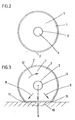
- Fig. 3
- eine der Fig. 2 entsprechende Darstellung in peripherem Berührungszustand der Transportwalze und
- Fig. 4
- einen vergrößerten Randschnitt der Transportwalze unter Verdeutlichung der Verankerung der Haut in den peripheren Poren des offenzelligen Schaumstoffmateriales.
- Die dargestellte Transportwalze besitzt einen aus offenzelligem, weichem Schaumstoff bestehenden Walzenkörper 1. Mindestens dessen Mantelfläche trägt eine Haut 2 aus nachgiebigem Material.
- Bezüglich des offenzelligen Schaumstoffes ist beispielsweise auf Polyurethan der Stauchhärte von 15-30 k Pa zurückgegriffen. Auf dem Gebiet der leichten weichen Schaumstoffe bieten sich auch Ester-/Ether-Polyethylen, Silikon etc. an. Dabei ist auf eine gute Feinzelligkeit des Materiales abgestellt (ab ca. 30 PPI).
- Die demgegenüber härtere, verschleißfestere Haut 2 besteht ebenfalls aus Polyurethan mit einer Shore-A-Härte von 73-83 und einer Bruchdehnung von 400%.
- Bei Anwendung einer flüssigen hautbildenden Beschichtung ist bezüglich der Auftragsweise auf das Sprühen zurückgegriffen. Andererseits ist aber auch eine gießtechnische Zuordnung ebenso denkbar wie das Rakeln oder Walzen. In all diesen Fällen kann eine so hochgradige Geschlossenheit der Haut eingestellt werden, daß das Eindringen von Flüssigkeit durch den so beschichteten Walzenmantel hindurch ausgeschlossen ist. Bei entsprechendem Einsatz, wo das Eindringen von Flüssigkeit in den offenzelligen Schaumstoff des Walzenkörpers generell ausgeschlossen werden soll, empfiehlt es sich, auch die beiden kreisringförmigen Stirnflächen 1ʹ des zylindrisch gestalteten Walzenkörpers 1 zu schließen. Einbezogen werden kann auch die zentrale Höhlung 3, welche eine Drehachse 4 aus unelastischem Material aufnimmt, die mit dem Walzenkörper 1 drehfest verbunden ist.
- Durch eine entsprechend allseitige Beschichtung ergibt sich ein hermetischer Abschluß. Ein solcher Walzenkörper wirkt daher wie ein weich gefülltes "Kissen". Der eingeschlossene Schaumstoff fungiert als gut nachgiebige, sich stets schnell zurückstellende Füllung im Hinblick auf die Verlagerung bei Berührungsflächenanlage. Diesbezüglich wird auf die Situation in Fig. 3 verwiesen. Es liegt dann eine Elastizitäteffekt sowohl aus den entsprechenden Eigenschaften des Schaumstoffes vor wie auch ein pneumatischer Elastizitätseffekt.
- Die ohne den Einsatz von Klebern erreichbare Fixierung der Haut 2 am Walzenkörper 1 ist besonders haltbar durch Eingriff des hautbildenden Materiales in die offenzellige Schaumstoffstruktur. Dies geht augenfällig aus Fig. 4 hervor. Während die Außenfläche 2ʹ der Haut 2 glatt gewölbt verläuft, setzt sich die den porösen Mantel 5 des Wabenkörpers 1 abdeckende Innenfläche 2" in letztere walzeneinwärts überragende Hautvorsprünge 6 fort. Diese verankern sich in den Poren 7 des Schaumstoffgerüsts 8. Die Schaumstoffporen 7 sind von unterschiedlicher Gestalt. Je nach Anschnitt weiten sie sich gerüstseitig erheblich. So entstehen Hinterschneidungsflächen 7ʹ. Da benachbarte Poren 7 zufolge der durchgehend offenzelligen Struktur auch über Querschächte miteinander verbunden sind, ergeben sich z. T. zusammenhängende Haut-Verankerungsschlaufen. Insgesamt ist eine hochgradig stabile Verankerung der Haut 2 erzielt gegebenenfalls unterstützt noch durch eine gewisse Haftwirkung der beiden Materialien zueinander.
- Die Hautdicke liegt zweckmäßig in einer Größenordnung von 0,1 bis 3,0 mm, je nach Größe der Walze und dem speziellen Einsatzzweck. Dabei ist die Verankerungstiefe x der Haut 2 in den Schaumstoffporen 8 etwa gleich der Dicke y der Haut. Zurückkommend auf das in Fig. 3 gezeigte Einsatzbild der Transportwalze erfolgt ein radial gerichtete Komprimierung unter Verdrängung eines kreisabschnittförmigen Walzenbereichs, welcher sich unter Bildung von mit Pfeil 9 bezeichneten Ausgleichskomponenten seitlich zur Radialen R verteilt. Der ideelle Umfangsabschnitt der Transportwalze ist mit 10 bezeichnet. Die Ausläufer des kreisabschnittförmigen Abschnitts gehen in in je eine Auswellung 11 über, die die Berührungsfläche praktisch noch weiter vergrößern.
- Der in Fig. 3 eingezeichnete Pfeil 12 gibt die Umlaufrichtung der Transportwalze an.
Claims (2)
- Aus elastischem offenzelligem Schaumstoff bestehende Transportwalze mit einer sich durch Eingriff in die Schaumstoffporen (7) verankernden geschlossene Haut (2) aus nachgiebigem Material, welche Transportwalze eine in zentraler Höhlung (3) angeordnete Drehachse (4) aus unelastischem Material aufweist, gekennzeichnet durch einen hermetisch oberflächenverschlossenen, vollständig verhauteten Walzenkörper (1).
- Transportwalze nach Anspruch 1, dadurch gekennzeichnet, daß die Verankerungstiefe (x) der Haut (2) in den Schaumstoffporen (7) etwa gleich der Dicke (y) der Haut (2) ist.
Priority Applications (1)
| Application Number | Priority Date | Filing Date | Title |
|---|---|---|---|
| AT87118678T ATE70021T1 (de) | 1987-01-07 | 1987-12-16 | Transportwalze. |
Applications Claiming Priority (2)
| Application Number | Priority Date | Filing Date | Title |
|---|---|---|---|
| DE8700258U DE8700258U1 (de) | 1987-01-07 | 1987-01-07 | Transportwalze |
| DE8700258U | 1987-01-07 |
Publications (2)
| Publication Number | Publication Date |
|---|---|
| EP0274096A1 EP0274096A1 (de) | 1988-07-13 |
| EP0274096B1 true EP0274096B1 (de) | 1991-12-04 |
Family
ID=6803393
Family Applications (1)
| Application Number | Title | Priority Date | Filing Date |
|---|---|---|---|
| EP87118678A Expired - Lifetime EP0274096B1 (de) | 1987-01-07 | 1987-12-16 | Transportwalze |
Country Status (7)
| Country | Link |
|---|---|
| US (1) | US4837064A (de) |
| EP (1) | EP0274096B1 (de) |
| JP (1) | JPS63176240A (de) |
| AT (1) | ATE70021T1 (de) |
| DE (2) | DE8700258U1 (de) |
| ES (1) | ES2028040T3 (de) |
| GR (1) | GR3003290T3 (de) |
Families Citing this family (27)
| Publication number | Priority date | Publication date | Assignee | Title |
|---|---|---|---|---|
| FR2663311B1 (fr) * | 1990-06-14 | 1992-10-09 | Bourges Inst Univers Technolog | Trieur pour convoyeur. |
| US5146022A (en) * | 1990-08-23 | 1992-09-08 | Mobil Oil Corporation | High VI synthetic lubricants from cracked slack wax |
| US5160020A (en) * | 1990-11-09 | 1992-11-03 | Lindberg Corporation | Drive system for endless belt conveyors with rollers having driving, supporting and aligning features |
| US5449063A (en) * | 1990-11-09 | 1995-09-12 | Lindberg Corporation | Modified drive system for endless belt conveyors with rollers having driving, supporting and aligning features |
| FI92419C (fi) * | 1990-11-19 | 1994-11-10 | Valmet Paper Machinery Inc | Menetelmä telan pinnoittamiseksi ja telapinnoite |
| GB9104104D0 (en) * | 1991-02-27 | 1991-04-17 | Watkiss Automation Ltd | Sheet feeding device |
| US5363129A (en) * | 1991-10-31 | 1994-11-08 | Hewlett-Packard Company | Printing media feed and retaining apparatus for a thermal ink jet printer/plotter |
| GB2265438A (en) * | 1992-01-03 | 1993-09-29 | Tong Chi Kwan | A roller, having an outer skin, for a printing press conveyor |
| FR2689871A1 (fr) * | 1992-04-10 | 1993-10-15 | Interroll Sa | Transporteur accumulateur à rouleaux montés fous sur des arbres transversaux entraînés en rotation . |
| US5206992A (en) * | 1992-06-12 | 1993-05-04 | American Roller Company | Compressible roller |
| EP0590561A1 (de) * | 1992-10-01 | 1994-04-06 | SCM S.p.A. | Antriebsrolle für zu bearbeitende Stücke |
| JPH07172615A (ja) * | 1993-12-15 | 1995-07-11 | Nec Corp | プレッシャローラ装置 |
| DE4414396C3 (de) * | 1994-04-26 | 2002-02-07 | Jagenberg Papiertech Gmbh | Trag- oder Stützwalze für eine Wickelmaschine |
| DE59610725D1 (de) * | 1995-02-21 | 2003-10-30 | Voith Paper Gmbh & Co Kg | Vorrichtung zum Auf bzw. Abwickeln von bahnförmigem Gut, insbesondere von Faserstoffbahnen |
| DE19505870C2 (de) * | 1995-02-21 | 2000-01-13 | Voith Sulzer Papiermasch Gmbh | Vorrichtung zum Auf- bzw. Abwickeln von bahnförmigem Gut, insbesondere von Faserstoffbahnen |
| DE19543516C2 (de) * | 1995-11-22 | 1999-04-29 | Enbi Nuth Bv | Transportelement für flächiges Gut |
| ES2145568T3 (es) * | 1996-01-30 | 2000-07-01 | Jagenberg Papiertech Gmbh | Rodillo para una maquina bobinadora. |
| WO1998056703A1 (en) * | 1997-06-13 | 1998-12-17 | Minnesota Mining And Manufacturing Company | Pinch wheels for an ink jet printer |
| GB2341569A (en) * | 1998-09-15 | 2000-03-22 | Rover Group | Stock support for a press tool |
| US6615490B2 (en) | 2000-01-21 | 2003-09-09 | Newell Operating Company | Method of manufacture of paint application |
| JP4366122B2 (ja) * | 2003-06-24 | 2009-11-18 | 日立オムロンターミナルソリューションズ株式会社 | 紙葉類搬送装置 |
| ES2453144T3 (es) | 2006-08-29 | 2014-04-04 | Agfa Healthcare | Dispositivo y método para la lectura de placas luminiscentes de almacenamiento |
| US20090045029A1 (en) * | 2007-08-16 | 2009-02-19 | Deur Delwyn G | Conveyor roller and cartridge bearing assembly for same |
| DE102012103966A1 (de) | 2012-05-07 | 2013-11-07 | Contitech Transportbandsysteme Gmbh | Förderanlage mit verbessertem Trommelbelag für die Antriebstrommel und / oder Umkehrtrommel und / oder Tragtrommel |
| KR101669128B1 (ko) | 2012-10-19 | 2016-10-25 | 사토 홀딩스 가부시키가이샤 | 탄성체 롤러 |
| JP6012404B2 (ja) * | 2012-10-31 | 2016-10-25 | サトーホールディングス株式会社 | 弾性体ローラー、弾性体ローラーによる帯状部材の移送方法および貼付け方法 |
| JP6484121B2 (ja) * | 2015-06-15 | 2019-03-13 | 株式会社イノアック技術研究所 | ロールおよびロールの製造方法 |
Family Cites Families (8)
| Publication number | Priority date | Publication date | Assignee | Title |
|---|---|---|---|---|
| US2157096A (en) * | 1939-05-09 | Thermal insulation | ||
| US2354430A (en) * | 1941-04-03 | 1944-07-25 | Firestone Tire & Rubber Co | Method of strengthening porous rubber articles and article produced |
| US2594348A (en) * | 1947-01-18 | 1952-04-29 | Dayton Rubber Company | Rubber covered roll |
| US3511738A (en) * | 1966-06-13 | 1970-05-12 | John S Mcguire | Hollow structural members and method of treating an interior surface thereof |
| DE2005211C3 (de) * | 1970-02-05 | 1974-10-31 | Fritz Teske | Tragrolle für Fördervorrichtungen, Förderbänder u.dgl |
| US4287649A (en) * | 1978-08-04 | 1981-09-08 | Truly Magic Products, Inc. | Roller construction for paper feeding |
| CA1197359A (en) * | 1982-03-24 | 1985-12-03 | Yutaka Hirano | Construction material and method of manufacturing the same |
| JPS61150370U (de) * | 1985-03-08 | 1986-09-17 |
-
1987
- 1987-01-07 DE DE8700258U patent/DE8700258U1/de not_active Expired
- 1987-12-16 EP EP87118678A patent/EP0274096B1/de not_active Expired - Lifetime
- 1987-12-16 DE DE8787118678T patent/DE3775022D1/de not_active Expired - Fee Related
- 1987-12-16 ES ES198787118678T patent/ES2028040T3/es not_active Expired - Fee Related
- 1987-12-16 AT AT87118678T patent/ATE70021T1/de not_active IP Right Cessation
- 1987-12-30 US US07/139,465 patent/US4837064A/en not_active Expired - Fee Related
-
1988
- 1988-01-07 JP JP63000795A patent/JPS63176240A/ja active Pending
-
1991
- 1991-12-05 GR GR91401899T patent/GR3003290T3/el unknown
Also Published As
| Publication number | Publication date |
|---|---|
| US4837064A (en) | 1989-06-06 |
| GR3003290T3 (en) | 1993-02-17 |
| JPS63176240A (ja) | 1988-07-20 |
| DE8700258U1 (de) | 1988-05-05 |
| EP0274096A1 (de) | 1988-07-13 |
| ATE70021T1 (de) | 1991-12-15 |
| DE3775022D1 (de) | 1992-01-16 |
| ES2028040T3 (es) | 1992-07-01 |
Similar Documents
| Publication | Publication Date | Title |
|---|---|---|
| EP0274096B1 (de) | Transportwalze | |
| DE10200387B4 (de) | Stent | |
| EP0847733B1 (de) | Stent | |
| EP0178483B1 (de) | Prothese als Ersatz für eine amputierte Brust | |
| DE60124772T2 (de) | Verfahren und vorrichtung zur herstellung eines intravaskulären stents | |
| DE2841505C2 (de) | Hydraulisch dämpfendes Gummilager | |
| DE3307475C2 (de) | ||
| DE2329719A1 (de) | Becherfoermige vorrichtung zum auffangen von menstruationsfluessigkeit zur inneren anwendung | |
| EP1136043A2 (de) | Stent | |
| DE3320063A1 (de) | Dichtring fuer radialwaelzlager | |
| DE4225379C2 (de) | Verfahren zur Herstellung einer Flachdichtung | |
| WO2004043295A1 (de) | Tragstruktur | |
| EP1212992B1 (de) | Implantat | |
| DE3229401A1 (de) | Hydraulische daempfungsvorrichtung | |
| DE3146673C2 (de) | Zier- oder Dichtleiste mit U-Profil | |
| DE102004045224A1 (de) | Stützprothese | |
| WO2001008990A1 (de) | Behälter mit innenbeutel | |
| WO2012110235A1 (de) | Verfahren zur herstellung eines behälters für ein füllgut | |
| DE20207243U1 (de) | Hülse mit verformbarer, harter Außenschicht, und mittels einer derartigen Hülse gebildeter Flexodruckkörper | |
| DE3802580C2 (de) | ||
| DE1026647B (de) | Notlaufring fuer Fahrzeugluftreifen und Verfahren zu seiner Herstellung und Einbringung | |
| DE4211347C2 (de) | Pfanne für eine Hüftgelenk-Endoprothese | |
| DE19909046B4 (de) | Akustischer Mehrschichtenabsorber, Verfahren zu dessen Herstellung und dessen Verwendung | |
| AT521339B1 (de) | Lackierwalze | |
| DE2237516A1 (de) | Torsionselastisches federungselement, insbesondere drehfederachse fuer ein fahrzeug, und verfahren zum herstellen eines federungselementes |
Legal Events
| Date | Code | Title | Description |
|---|---|---|---|
| PUAI | Public reference made under article 153(3) epc to a published international application that has entered the european phase |
Free format text: ORIGINAL CODE: 0009012 |
|
| AK | Designated contracting states |
Kind code of ref document: A1 Designated state(s): AT BE CH DE ES FR GB GR IT LI LU NL SE |
|
| 17P | Request for examination filed |
Effective date: 19881003 |
|
| 17Q | First examination report despatched |
Effective date: 19891201 |
|
| GRAA | (expected) grant |
Free format text: ORIGINAL CODE: 0009210 |
|
| AK | Designated contracting states |
Kind code of ref document: B1 Designated state(s): AT BE CH DE ES FR GB GR IT LI LU NL SE |
|
| REF | Corresponds to: |
Ref document number: 70021 Country of ref document: AT Date of ref document: 19911215 Kind code of ref document: T |
|
| ET | Fr: translation filed | ||
| REF | Corresponds to: |
Ref document number: 3775022 Country of ref document: DE Date of ref document: 19920116 |
|
| ITF | It: translation for a ep patent filed | ||
| GBT | Gb: translation of ep patent filed (gb section 77(6)(a)/1977) | ||
| REG | Reference to a national code |
Ref country code: ES Ref legal event code: FG2A Ref document number: 2028040 Country of ref document: ES Kind code of ref document: T3 |
|
| PLBE | No opposition filed within time limit |
Free format text: ORIGINAL CODE: 0009261 |
|
| STAA | Information on the status of an ep patent application or granted ep patent |
Free format text: STATUS: NO OPPOSITION FILED WITHIN TIME LIMIT |
|
| REG | Reference to a national code |
Ref country code: GR Ref legal event code: FG4A Free format text: 3003290 |
|
| 26N | No opposition filed | ||
| PGFP | Annual fee paid to national office [announced via postgrant information from national office to epo] |
Ref country code: GR Payment date: 19931229 Year of fee payment: 7 |
|
| EPTA | Lu: last paid annual fee | ||
| PGFP | Annual fee paid to national office [announced via postgrant information from national office to epo] |
Ref country code: SE Payment date: 19941215 Year of fee payment: 8 |
|
| EAL | Se: european patent in force in sweden |
Ref document number: 87118678.9 |
|
| PG25 | Lapsed in a contracting state [announced via postgrant information from national office to epo] |
Ref country code: GR Free format text: THE PATENT HAS BEEN ANNULLED BY A DECISION OF A NATIONAL AUTHORITY Effective date: 19950630 |
|
| REG | Reference to a national code |
Ref country code: GR Ref legal event code: MM2A Free format text: 3003290 |
|
| PGFP | Annual fee paid to national office [announced via postgrant information from national office to epo] |
Ref country code: LU Payment date: 19951101 Year of fee payment: 9 |
|
| PGFP | Annual fee paid to national office [announced via postgrant information from national office to epo] |
Ref country code: FR Payment date: 19951129 Year of fee payment: 9 |
|
| PGFP | Annual fee paid to national office [announced via postgrant information from national office to epo] |
Ref country code: AT Payment date: 19951213 Year of fee payment: 9 |
|
| PG25 | Lapsed in a contracting state [announced via postgrant information from national office to epo] |
Ref country code: SE Effective date: 19951217 |
|
| PGFP | Annual fee paid to national office [announced via postgrant information from national office to epo] |
Ref country code: CH Payment date: 19960124 Year of fee payment: 9 |
|
| PG25 | Lapsed in a contracting state [announced via postgrant information from national office to epo] |
Ref country code: LU Free format text: LAPSE BECAUSE OF NON-PAYMENT OF DUE FEES Effective date: 19961216 Ref country code: AT Effective date: 19961216 |
|
| PG25 | Lapsed in a contracting state [announced via postgrant information from national office to epo] |
Ref country code: LI Effective date: 19961231 Ref country code: CH Effective date: 19961231 |
|
| PGFP | Annual fee paid to national office [announced via postgrant information from national office to epo] |
Ref country code: BE Payment date: 19970214 Year of fee payment: 10 |
|
| REG | Reference to a national code |
Ref country code: CH Ref legal event code: PL |
|
| PG25 | Lapsed in a contracting state [announced via postgrant information from national office to epo] |
Ref country code: FR Effective date: 19970829 |
|
| REG | Reference to a national code |
Ref country code: FR Ref legal event code: ST |
|
| PGFP | Annual fee paid to national office [announced via postgrant information from national office to epo] |
Ref country code: GB Payment date: 19971114 Year of fee payment: 11 |
|
| PGFP | Annual fee paid to national office [announced via postgrant information from national office to epo] |
Ref country code: NL Payment date: 19971118 Year of fee payment: 11 |
|
| PGFP | Annual fee paid to national office [announced via postgrant information from national office to epo] |
Ref country code: ES Payment date: 19971230 Year of fee payment: 11 |
|
| PG25 | Lapsed in a contracting state [announced via postgrant information from national office to epo] |
Ref country code: BE Free format text: LAPSE BECAUSE OF NON-PAYMENT OF DUE FEES Effective date: 19971231 |
|
| BERE | Be: lapsed |
Owner name: IRBIT RESEARCH + CONSULTING A.G. Effective date: 19971231 |
|
| PG25 | Lapsed in a contracting state [announced via postgrant information from national office to epo] |
Ref country code: GB Free format text: LAPSE BECAUSE OF NON-PAYMENT OF DUE FEES Effective date: 19981216 |
|
| PG25 | Lapsed in a contracting state [announced via postgrant information from national office to epo] |
Ref country code: NL Free format text: LAPSE BECAUSE OF NON-PAYMENT OF DUE FEES Effective date: 19990701 |
|
| GBPC | Gb: european patent ceased through non-payment of renewal fee |
Effective date: 19981216 |
|
| NLV4 | Nl: lapsed or anulled due to non-payment of the annual fee |
Effective date: 19990701 |
|
| PGFP | Annual fee paid to national office [announced via postgrant information from national office to epo] |
Ref country code: DE Payment date: 19991203 Year of fee payment: 13 |
|
| PG25 | Lapsed in a contracting state [announced via postgrant information from national office to epo] |
Ref country code: ES Free format text: LAPSE BECAUSE OF NON-PAYMENT OF DUE FEES Effective date: 19991217 |
|
| PG25 | Lapsed in a contracting state [announced via postgrant information from national office to epo] |
Ref country code: DE Free format text: LAPSE BECAUSE OF NON-PAYMENT OF DUE FEES Effective date: 20011002 |
|
| REG | Reference to a national code |
Ref country code: ES Ref legal event code: FD2A Effective date: 20000114 |
|
| PG25 | Lapsed in a contracting state [announced via postgrant information from national office to epo] |
Ref country code: IT Free format text: LAPSE BECAUSE OF NON-PAYMENT OF DUE FEES;WARNING: LAPSES OF ITALIAN PATENTS WITH EFFECTIVE DATE BEFORE 2007 MAY HAVE OCCURRED AT ANY TIME BEFORE 2007. THE CORRECT EFFECTIVE DATE MAY BE DIFFERENT FROM THE ONE RECORDED. Effective date: 20051216 |