EP0274080B1 - Système de commande des embrayages de marche avant et marche arrière d'une transmission continue de vitesse à courroie - Google Patents
Système de commande des embrayages de marche avant et marche arrière d'une transmission continue de vitesse à courroie Download PDFInfo
- Publication number
- EP0274080B1 EP0274080B1 EP87118317A EP87118317A EP0274080B1 EP 0274080 B1 EP0274080 B1 EP 0274080B1 EP 87118317 A EP87118317 A EP 87118317A EP 87118317 A EP87118317 A EP 87118317A EP 0274080 B1 EP0274080 B1 EP 0274080B1
- Authority
- EP
- European Patent Office
- Prior art keywords
- pressure
- line
- clutch
- accumulator
- valve
- Prior art date
- Legal status (The legal status is an assumption and is not a legal conclusion. Google has not performed a legal analysis and makes no representation as to the accuracy of the status listed.)
- Expired - Lifetime
Links
- 230000005540 biological transmission Effects 0.000 title claims description 23
- 239000012530 fluid Substances 0.000 claims description 22
- 230000001105 regulatory effect Effects 0.000 claims description 16
- 230000007935 neutral effect Effects 0.000 claims description 8
- 238000004891 communication Methods 0.000 claims description 4
- 238000013022 venting Methods 0.000 claims description 2
- 238000004804 winding Methods 0.000 description 9
- 230000000694 effects Effects 0.000 description 3
- 238000010586 diagram Methods 0.000 description 2
- 238000006073 displacement reaction Methods 0.000 description 2
- 230000003213 activating effect Effects 0.000 description 1
- 230000033228 biological regulation Effects 0.000 description 1
- 230000003750 conditioning effect Effects 0.000 description 1
- 230000001276 controlling effect Effects 0.000 description 1
- 238000013016 damping Methods 0.000 description 1
- 230000003247 decreasing effect Effects 0.000 description 1
- 230000001419 dependent effect Effects 0.000 description 1
- 230000013011 mating Effects 0.000 description 1
- 230000000630 rising effect Effects 0.000 description 1
- 238000007789 sealing Methods 0.000 description 1
- 239000007858 starting material Substances 0.000 description 1
- 238000011144 upstream manufacturing Methods 0.000 description 1
Images


Classifications
-
- B—PERFORMING OPERATIONS; TRANSPORTING
- B60—VEHICLES IN GENERAL
- B60W—CONJOINT CONTROL OF VEHICLE SUB-UNITS OF DIFFERENT TYPE OR DIFFERENT FUNCTION; CONTROL SYSTEMS SPECIALLY ADAPTED FOR HYBRID VEHICLES; ROAD VEHICLE DRIVE CONTROL SYSTEMS FOR PURPOSES NOT RELATED TO THE CONTROL OF A PARTICULAR SUB-UNIT
- B60W30/00—Purposes of road vehicle drive control systems not related to the control of a particular sub-unit, e.g. of systems using conjoint control of vehicle sub-units
- B60W30/18—Propelling the vehicle
-
- B—PERFORMING OPERATIONS; TRANSPORTING
- B60—VEHICLES IN GENERAL
- B60W—CONJOINT CONTROL OF VEHICLE SUB-UNITS OF DIFFERENT TYPE OR DIFFERENT FUNCTION; CONTROL SYSTEMS SPECIALLY ADAPTED FOR HYBRID VEHICLES; ROAD VEHICLE DRIVE CONTROL SYSTEMS FOR PURPOSES NOT RELATED TO THE CONTROL OF A PARTICULAR SUB-UNIT
- B60W10/00—Conjoint control of vehicle sub-units of different type or different function
- B60W10/04—Conjoint control of vehicle sub-units of different type or different function including control of propulsion units
-
- B—PERFORMING OPERATIONS; TRANSPORTING
- B60—VEHICLES IN GENERAL
- B60W—CONJOINT CONTROL OF VEHICLE SUB-UNITS OF DIFFERENT TYPE OR DIFFERENT FUNCTION; CONTROL SYSTEMS SPECIALLY ADAPTED FOR HYBRID VEHICLES; ROAD VEHICLE DRIVE CONTROL SYSTEMS FOR PURPOSES NOT RELATED TO THE CONTROL OF A PARTICULAR SUB-UNIT
- B60W10/00—Conjoint control of vehicle sub-units of different type or different function
- B60W10/10—Conjoint control of vehicle sub-units of different type or different function including control of change-speed gearings
- B60W10/101—Infinitely variable gearings
-
- B—PERFORMING OPERATIONS; TRANSPORTING
- B60—VEHICLES IN GENERAL
- B60W—CONJOINT CONTROL OF VEHICLE SUB-UNITS OF DIFFERENT TYPE OR DIFFERENT FUNCTION; CONTROL SYSTEMS SPECIALLY ADAPTED FOR HYBRID VEHICLES; ROAD VEHICLE DRIVE CONTROL SYSTEMS FOR PURPOSES NOT RELATED TO THE CONTROL OF A PARTICULAR SUB-UNIT
- B60W30/00—Purposes of road vehicle drive control systems not related to the control of a particular sub-unit, e.g. of systems using conjoint control of vehicle sub-units
- B60W30/18—Propelling the vehicle
- B60W30/1819—Propulsion control with control means using analogue circuits, relays or mechanical links
-
- F—MECHANICAL ENGINEERING; LIGHTING; HEATING; WEAPONS; BLASTING
- F16—ENGINEERING ELEMENTS AND UNITS; GENERAL MEASURES FOR PRODUCING AND MAINTAINING EFFECTIVE FUNCTIONING OF MACHINES OR INSTALLATIONS; THERMAL INSULATION IN GENERAL
- F16H—GEARING
- F16H61/00—Control functions within control units of change-speed- or reversing-gearings for conveying rotary motion ; Control of exclusively fluid gearing, friction gearing, gearings with endless flexible members or other particular types of gearing
- F16H61/66—Control functions within control units of change-speed- or reversing-gearings for conveying rotary motion ; Control of exclusively fluid gearing, friction gearing, gearings with endless flexible members or other particular types of gearing specially adapted for continuously variable gearings
- F16H61/662—Control functions within control units of change-speed- or reversing-gearings for conveying rotary motion ; Control of exclusively fluid gearing, friction gearing, gearings with endless flexible members or other particular types of gearing specially adapted for continuously variable gearings with endless flexible members
- F16H61/66254—Control functions within control units of change-speed- or reversing-gearings for conveying rotary motion ; Control of exclusively fluid gearing, friction gearing, gearings with endless flexible members or other particular types of gearing specially adapted for continuously variable gearings with endless flexible members controlling of shifting being influenced by a signal derived from the engine and the main coupling
- F16H61/66259—Control functions within control units of change-speed- or reversing-gearings for conveying rotary motion ; Control of exclusively fluid gearing, friction gearing, gearings with endless flexible members or other particular types of gearing specially adapted for continuously variable gearings with endless flexible members controlling of shifting being influenced by a signal derived from the engine and the main coupling using electrical or electronical sensing or control means
-
- F—MECHANICAL ENGINEERING; LIGHTING; HEATING; WEAPONS; BLASTING
- F16—ENGINEERING ELEMENTS AND UNITS; GENERAL MEASURES FOR PRODUCING AND MAINTAINING EFFECTIVE FUNCTIONING OF MACHINES OR INSTALLATIONS; THERMAL INSULATION IN GENERAL
- F16H—GEARING
- F16H61/00—Control functions within control units of change-speed- or reversing-gearings for conveying rotary motion ; Control of exclusively fluid gearing, friction gearing, gearings with endless flexible members or other particular types of gearing
- F16H61/66—Control functions within control units of change-speed- or reversing-gearings for conveying rotary motion ; Control of exclusively fluid gearing, friction gearing, gearings with endless flexible members or other particular types of gearing specially adapted for continuously variable gearings
- F16H2061/6604—Special control features generally applicable to continuously variable gearings
- F16H2061/6605—Control for completing downshift at hard braking
-
- F—MECHANICAL ENGINEERING; LIGHTING; HEATING; WEAPONS; BLASTING
- F16—ENGINEERING ELEMENTS AND UNITS; GENERAL MEASURES FOR PRODUCING AND MAINTAINING EFFECTIVE FUNCTIONING OF MACHINES OR INSTALLATIONS; THERMAL INSULATION IN GENERAL
- F16H—GEARING
- F16H61/00—Control functions within control units of change-speed- or reversing-gearings for conveying rotary motion ; Control of exclusively fluid gearing, friction gearing, gearings with endless flexible members or other particular types of gearing
- F16H61/66—Control functions within control units of change-speed- or reversing-gearings for conveying rotary motion ; Control of exclusively fluid gearing, friction gearing, gearings with endless flexible members or other particular types of gearing specially adapted for continuously variable gearings
- F16H2061/6604—Special control features generally applicable to continuously variable gearings
- F16H2061/6608—Control of clutches, or brakes for forward-reverse shift
Definitions
- This invention relates to a system for actuating forward drive and reverse drive clutches in a continually variable transmission.
- a continuously variable transmission of the kind as for example shown in EP-A-0 061 732 includes an endless belt which is driveably engaged with a primary pulley and a secondary pulley. Each pulley is supported rotatably on a shaft that includes an axially displaceable sheave which is moved by a fluid-operated servo to change the radial position of the belt on the pulley in accordance with a commanded drive ratio.
- Forward drive and reverse drive are provided by a pair of gearsets which are driven by the secondary pulley on the same axis as the conventional differential wherey the selection of any of these forward and reverse drives is made via mechanical controlled hydraulically activated multiple disc clutches.
- the hydraulic circuit activating the operation of these clutches includes in general a source of line pressure which is normally a regulator valve connected to the discharge side of a hydraulic pump and further manual valve means being selectively movable manually by the vehicle operator among reverse drive, neutral and forward drive positions for directing fluid to the clutches in accordance with the selected drive position.
- the system also includes valve means for producing line control pressure in accordance with a command for clutch engagement.
- the present invention deals with the object of providing a forward and reverse clutch actuating system which secures a smooth engagement of the particularly selected clutch with the aid of some increased volume of the hydraulic fluid as added to the volumetric flow rate of the hydraulic pump to thereby minimize at the same time the usual delay in the engagement of the clutches.
- the clutch when the command for engagement of the particular clutch is received, the clutch is then filled by a connection of the line pressure source through an orifice and by adding to the orifice flow the flow from the accumulator which bypasses the orifice.
- the variable force solenoid pressure When the clearances of the clutch components are taken up and the friction surfaces of the plates are in position to transmit torque, the variable force solenoid pressure then regulates pressure in the clutch cylinder while allowing the accumulator to refill through a connection to the line pressure source. This permits a moderate rate of flow to the cylinder through the orifice, thereby avoiding harsh engagement and minimizing engagement delay.
- Only one accumulator and one orifice is required to feed both the forward and the reverse clutches because all of the flow from the accumulator and the orifice is directed by the manual valve to the selected clutch.
- Each clutch is vented through the manual valve when it is moved to the neutral position located between the forward drive positions and the reverse drive position.
- the manual valve directs hydraulic fluid from the accumulator and from the line pressure source to the forward clutch when the PRNDL selector is moved to any of the forward drive positions.
- the deceleration disconnect valve is located so that the flow from the accumulator and the line pressure source to the manual valve actually passes through this valve.
- the deceleration disconnect valve closes the flow to the forward clutch and the pressure in the clutch cylinder is then regulated in accordance with a pulse width modulated signal energizing and deenergizing the winding of its operational solenoid to a pressure sufficient to hold the friction surfaces of the clutch discs in contact but not to transmit any appreciable torque.
- the regulated pressure during the hard braking condition is thusly maintained at a pressure such that the force on the clutch piston slightly exceeds the force of the return spring, thereby assuring that the clearances within the clutch are removed and the clutch is disposed for immediate torque transmittal.
- Disengagement of the forward clutch during a hard braking condition assures that the pulleys of the transmission can continue to turn sufficiently to bring the transmission to the lowest drive ratio condition and also assures that the vehicle can be reaccelerated immediately and without delay after the braking condition is concluded.
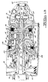
- Figures 1A and 1B form a schematic diagram of a transmission whose operation is suitably controlled by this invention.
- Figure 2 is a schematic diagram of the electronic and hydraulic components of the control system for operating an automatic transmission.
- FIGS 3A and 3B show the details of the hydraulic and electrical control.
- an automatic transmission in particular a continually variable transmission for use in front-wheel drive vehicle whose engine and transmission are transversely mounted, includes a torque converter 10 driveably connected to an engine crankshaft 12, a primary or input variable diameter pulley 14, a secondary or output variable diameter pulley 16, final drive gearing and a differential mechanism 20.
- the flywheel 22 fixed to the crankshaft has a starter gear 24 carried on its circumference.
- the torque converter includes an impeller 26, which is driven mechanically from the crankshaft, a turbine 28 driven hydrodynamically from the impeller and connected mechanically to a shaft 30, and a stator 32 connected by a one-way clutch 34 whose inner surfaces are splined to the rotor of a fixed displacement hydraulic pump 36.
- the turbine When the turbine is driven hydrodynamically from the impeller by the fluid contained in the torque converter, the transmission operates in the converter mode.
- the disc 38 which connects the crankshaft to the blades of the impeller 26, and the adjacent disc 40, which is joined by a spline to shaft 30, carry mating friction surfaces and form collectively a lockup or slipping clutch 42 that selectively produces a mechanical connection between impeller 26 and turbine 28 when clutch 42 is engaged, or permits a hydrodynamic drive connection between them when the clutch is disengaged.
- Lockup clutch pressure supplied to the converter casing in cylinder 44 causes or tends to cause the clutch friction surfaces to driveably engage.
- Converter feed pressure supplied in passage 46 tends to separate the friction surfaces and allows clutch 42 to slip while some frictional contact is maintained on its friction surfaces, or to entirely disengage the clutch depending upon the magnitude of the hydraulic pressure supplied through line 46 and the opposing effect of the hydraulic pressure within cylinder 44.
- the primary pulley 14 includes a fixed sheave 48, which is rotatably mounted on the support surfaces provided on the surface of pump 36 and at a bearing 50 on the transmission case.
- a displaceable sheave 52 is supported on the outer surface of sheave 48 for sliding movement toward and away from the fixed sheave.
- Sheave 52 is connected by a spline 66 to a disc 68 on which is formed angularly spaced teeth 72, which pass in front of a variable reluctance primary pulley speed sensor 74 to produce a signal whose frequency is a measure of the rotational speed of the primary pulley 14.
- Drive belt 64 is continually engaged also with the output or secondary pulley 16, which includes a fixed sheave 76 and a displaceable sheave 78.
- the rotational speed of the output pulley is determined by a signal produced by a variable reluctance speed sensor 88 located so that the teeth 90 on the outer surface of disc 92 pass in front of the speed sensor.
- Disc 92 supports on one end the diaphragm seals 80, 82, their other end being supported on displaceable sheave 78.
- Pressurized hydraulic fluid supplied through hydraulic passage 96 flows through spline 94 into cylinder 84 and pressurizes the outer surface of sheave 78, thereby moving drive belt 64 to a greater radial position on the secondary pulley 16 and to a lesser radial position on input pulley 14.
- Disc 92 is splined at 98 to the fixed sheave and provides driving continuity through spline 94 to sheave 78.
- Disc 68 is splined at 60 to fixed sheave 48 and at spline 66 to displaceable sheave 52, thereby driveably connecting sheaves 48 and 52.
- Sun gears 100 and 102 are formed integrally on a gear wheel that is splined at 104 to the sheaves that form the secondary pulley 16.
- Ring gear 110 is driveably connected to carrier 114 and ring gear 116 is selectively connected to the casing of the transmission through a forward drive clutch 118.
- Reverse drive clutch 120 selectively connects carrier 108 to the transmission casing.
- Clutch 120 includes a first set of clutch discs 126 splined to the transmission casing and a second set of discs 128 splined to carrier 108.
- Pressure block 130 reacts the pressure force developed on the face of the clutch piston 132 when the pressurized hydraulic fluid is admitted to clutch cylinder 134.
- Forward drive clutch 118 includes a first set of clutch discs 136 splined to the transmission casing and a second set of clutch discs 138 splined to disc 140, which is fixed to ring gear 116.
- Pressure block 142 reacts the pressure forces developed on the face of clutch piston 144 when hydraulic fluid is admitted to clutch cylinder 146.
- Spring 148 driveably disconnects clutch discs 136, 138 when cylinder 146 is vented.
- Figure 2 shows the various electric input signals supplied to a central processing unit and computer memory 172, the output signals produced by the computer and sent to the control elements of a valve body 174 and the hydraulic actuation signals produced by the valve body.
- Signal 176 representing the speed of the engine crankshaft and signal 178 representing the effective throttle angle position are taken from the engine and supplied as input to computer 172.
- a signal 180 representing the position of a PRNDL selector 182, controlled by the vehicle operator; a transmission oil temperature signal 184; a belt pressure signal 186; a lockup clutch pressure signal 188; the primary pulley speed signal 190; and secondary pulley speed signal 192 also are supplied as input to the computer.
- Output signals sent from the computer and its associated conditioning circuits to variable force solenoids or to pulse width modulation solenoids located in or adjacent the valve body include: ratio control solenoid signal 194, lockup clutch control solenoid signal 196, line/belt load control solenoid signal 198 and decel disconnect signal 200.
- the computer produces signals convertible to digital displays observable by the vehicle operator.
- the components of the valve body 174 produce from the three electrical control solenoid signals produced by the computer various hydraulic pressures that include line regulator pressure 202' in line 202, ratio control pressure in line 204, belt load pressure in line 206, lockup clutch pressure 208' in line 208, converter pressure regulation in line 210, forward/reverse clutch apply pressure in line 212, converter feed pressure 214' in line 214 and line boost pressure 216.
- a manual valve 220 (manual valve means 220), which is a six-position, two-land valve that provides park, reverse, neutral, drive, drive 2, and hill brake HB operation.
- manual valve means 220 When the manual valve is in the park position, reverse clutch 120 and forward clutch 118 are vented at the manual valve.
- the forward clutch is vented at the manual valve and regulated line or pump discharge pressure is supplied through lines 222, 232 and 396 to the manual valve. Input is directed to cylinder 134 of the reverse clutch through line 122.
- the manual valve is in the neutral position, the reverse and forward clutches are exhausted at the manual valve.
- the reverse clutch is vented and the forward clutch is pressurized from line 396 through line 226.
- the valve body 174 includes an accumulator control valve 228 and an accumulator 230, which rapidly fills alternately the reverse and forward clutches 120, 118.
- Control valve 228 provides flow control to the accumulator as a function of a magnitude of the throttle angle, as determined by computer input signal 178 and in accordance with the control pressure output by line and belt load control valve 240 (line control valve 240).
- the discharge side of the pump is connected by line 222 to the input of valve 228 and by line 232 through orifice 234 to a first end of accumulator 230, whose piston 236 is moved thereby to the left end of the accumulator cylinder as it is filled with fluid. Fluid remaining in the cylinder at the left side of the piston is vented from the second accumulator end through line 237, whose pressure forces the spool of valve 228 to the left end of the valve and closes input line 222. Springs 239, arranged coaxially and in parallel, bias piston 236 toward the first end of the accumulator. The forward and reverse clutch cylinders 146, 134 are exhausted through manual valve 220.
- decel disconnect valve deceleration disconnect valve means 370, which includes a spool 372 biased by a spring 374 to the position in Figure 3B; a first feedback passage 376 in the spool; solenoid 378; concentric axial passages (second feedback means) 380, 382; ball 384; seat 386 and plunger 388. Passages 390 and 392 connect the accumulator and the source of line pressure to valve 370.
- solenoid 378 is deenergized, ball 384 moves off seat 386 and opens passage 382 and 392, thereby aiding spring 374 to move spool 372 to the position of Figure 3B.
- the fluid is forced from the first end of the accumulator because accumulator control valve 228 receives a first control pressure in lines 202, 238 from belt/line control valve 240 when a command signal from the computer is applied to the windings of solenoid 242 in response to a shift of the PRNDL to a forward drive position from the neutral position and an increase in engine throttle position.
- the control pressure in line 238 forces spool 229 rightward, closes the connection between line 237 and the vent port of valve 228, and opens line pressure to the second end of the accumulator through line 237 and valve 228.
- clutch cylinder 146 is vented through valve 220 as the PRNDL selector moves to the neutral position; then the reverse clutch cylinder 134 is filled rapidly with flow through orifice 234 and from accumulator 230 through lines 390, 396 and 122.
- the computer produces a signal to the windings of solenoid 242, which moves spool 229 of control valve 228 to the right, thereby opening line 222 to the second end of the accumulator and forcing, with the force of springs 239, fluid from the right hand side of piston 236.
- the forward clutch pressure is controlled following this condition through operation of the decel disconnect solenoid, which receives a pulse width modulated PWM signal applied to its winding from the computer output when the hard braking condition is detected from the values supplied as input to the computer.
- Valve 370 is used to control the rate of pressure rise in clutch cylinder 146 to produce smooth engagement. Then the signal is removed from solenoid 378 and the forward clutch is pressurized with slight flow through orifice 234 from the line pressure source and through valves 370 and 220.
- the suction side of the fixed displacement pump 36 is supplied with hydraulic fluid from the sump through a screen 246, and the discharge side of the pump is connected by line 248 to the main regulator valve 244.
- the output from line boost valve 250 is carried in line 252 through orifice 254 and produces a pressure force on land 256, which combines with the force of spring 258 to oppose a net pressure force acting downward on land 259 of spool 260 to regulate the converter regulated feed pressure carried in line 262. If the pump discharge pressure is too high, spool 260 moves downward and connects line 248 to suction line 265, thereby reducing the pump pressure. If discharge pressure is too low, spool 260 moves upward due to the effect of line boost pressure and the force of spring 258, thereby sealing vent line 265 and allowing the discharge pressure to rise. Orifices 254 and 264 are provided to improve damping.
- Line boost valve 250 includes a spool 266 biased downward by a spring 268, a vent port 270, input line 272 connected by line 222 to the discharge side of the pump and an output port connected by line 252 to the end of regulator valve 244.
- Line boost valve 250 is used to regulate line boost pressure as a function of the line and belt load control VFS pressure carried in lines 238, 202.
- the output from the line boost valve is an input to the main regulator valve 244, which is used to increase line pressure in accordance with the magnitude of engine torque.
- boost valve 250 When line control VFS pressure in line 238 is between zero and a first predetermined pressure, boost valve 250 is not regulating and line control VFS pressure is ported directly to the main regulator valve in line 252.
- VFS pressure is equal to or greater than the first predetermined pressures, spool 266 moves upward against the force of spring 268 and line boost pressure in line 252 is regulated in accordance with line control VFS pressure which varies with engine torque.
- Lockup clutch control valve 274 is an unbalanced regulator valve used to modulate lockup clutch pressure in lines 214 and 282 as a function of the lockup clutch control VFS pressure carried in line 208.
- Clutch control VFS pressure is produced as output from the clutch control VFS valve 276 in accordance with a signal applied to the terminals 196 of clutch control variable force solenoid 278 for producing fluid flow to the clutch.
- the lockup clutch pressure causes the friction surfaces of lockup clutch 42 to engage and is modulated over a pressure range by modulating lockup clutch control VFS pressure.
- the minimum lockup clutch pressure is supplied in lines 282 and 214 to converter cylinder 44 when valve 274 is wide open, i.e. when lockup clutch control VFS pressure carried in line 208 is a maximum.
- Lube pressure is set at a low value determined by the spring 290 and the area of piston 292 of the lube relief valve 294. This sets the minimum pressure in converter cylinder 44, which opposes the effect of pressure within passage 46 of lockup clutch 42.
- the lockup clutch control VFS pressure declines as the engine throttle opens, thereby permitting spool 284 to regulate the pressure to lines 214 and 282 and cylinder 44 from the pressure in line 280.
- Converter regulator valve 296 is an unbalanced area valve used to regulate converter feed pressure as a function of lockup clutch pressure supplied from clutch control valve 274 through line 282.
- lockup clutch pressure force on clutch 42 is greater than the converter feed pressure force
- lockup clutch 42 is engaged and the torque converter is disabled.
- lockup clutch pressure force on clutch 42 is greater than lockup clutch pressure force
- the torque converter is operative.
- lockup clutch pressure is below 10 psi
- converter feed pressure is equal to line pressure less the pressure drop across orifice 264, but as lockup clutch pressure increases, the force it produces on land 300 acting in opposition to the force of spring 302 opens converter feed line 304 and line 298 to the lube relief valve 294 and regulates the converter feed pressure inversely as lockup clutch pressure increases.
- converter feed pressure is supplied from regulator valve 244 through orifice 264, line 262, 210, passage 46 and lockup clutch 42 to torque converter 10. This pressure disengages the friction surfaces of clutch 42 because the pressure force tending to engage clutch 42 is relatively low.
- the lockup clutch control VFS pressure supplied in line 208 to clutch control valve is high; therefore spool 284 closes line 280 and opens converter line 214 from the converter to cooler feed line 215.
- Relief valve 294 sets the maximum pressure in line 215 cooler and the lube circuit at 10 psi. Because converter feed pressure is high relative to lockup clutch pressure, converter regulator valve 296 regulates converter feed line 298 by dumping fluid to the lube relief valve when converter feed pressure exceeds 50-60 psi.
- the variable force solenoid VFS feed valve 306 is an unbalanced area pressure regulator valve used to regulate pump discharge pressure to a magnitude suitable for use by the VFS valves 240, 276 and 308.
- the force of spring 310 moves spool 312 to the fully opened position, thereby connecting regulated line pressure in line 222 to the VFS feed line 314; provided line pressure is below a predetermined value.
- the pressure force developed on land 316 by fluid fed back through line 318 moves spool 312 against the force of spring 310 and closes the connection between line pressure 222 and supply line 314, thereby limiting the VFS feed pressure to about 90 psi.
- Ratio control valve 320 is a pressure compensated flow control valve used to control hydraulic flow into and out of cylinder 58 of the primary belt pulley 14 to change the drive ratio of the belt-pulley system.
- ratio control VFS pressure produced by solenoid-operated valve 308 and supplied to ratio control valve 320 through line 322 is below a predetermined pressure
- regulated line pressure from the discharge side of the pump is directed to the primary pulley cylinder 58 through the ratio control valve, line 62 and orifice 330 to produce an overdrive ratio.
- ratio control VFS pressure is greater than this predetermined magnitude, regulated line pressure is directed away from cylinder 58 and cylinder 84 of the output pulley 16 is pressurized to produce a shift to a lower drive ratio.
- the output pressure range of the ratio control VFS solenoid valve 308 is zero to 90 psi.
- the VFS signal pressure range available is approximately 25 psi.
- the VFS signal pressure range available is 65 psi. Therefore, greater signal response is available when making a wide open throttle angle ratio change to underdrive operation.
- Ratio control valve 320 includes line pressure line 324 communicating with the discharge side of the pump, a first spool 326 biased upward within the valve chamber by spring 328, orifice 330 in the output line 332 through which primary pulley cylinder 58 is supplied, feedback line 334, having an orifice 336, orifice 338 in feedback line 340, and a valve element 342 held by hydraulic pressure force on land 344 in contact with spool 326.
- Pressure compensated flow control is incorporated in ratio control valve 320 so that flow into and out of primary pulley cylinder 58 is directly regulated by the VFS ratio control solenoid electrical signal and pressure in line 322 independently of pressure changes upstream and downstream from the valve.
- the valve is inherently self compensating to either pump discharge pressure or primary pulley cylinder pressure variations. For example, if VFS ratio control pressure is decreased to 20 psi, spool 326 moves upward, thereby connecting regulated line pressure in line 324 to line 332 and cylinder 58 through metering orifice 330. Spool 326 will stop moving upward when the force balance is reestablished. In the steady-state condition, the pressure drop across orifice 330 is proportional to the VFS control pressure. The primary pulley will move toward its overdrive position at a speed related to the fixed flow rate across orifice 330.
- Belt load valve 346 is an unbalanced pressure regulator valve used to control belt clamping load by controlling the pressure on the displaceable sheave 78, which moves in accordance with pressure supplied to cylinder 84 of output pulley 16.
- the belt clamping load requirement on the secondary pulley is a function of engine torque and the drive ratio to be produced by the belt-pulley system.
- Execution of a control algorithm in computer 172 determines the clamping loads, which are then converted to a belt load first control VFS pressure carried in lines 202 and 238 to belt load valve 346.
- Pressure in line 238 produces a force on spool 348 tending to open the connection between line pressure in line 350 and cylinder 84, which is supplied through line 352.
- Pressure carried in feedback line 354 produces a lesser force on spool 348 that opposes the force resulting from the pressure produced by line and belt load control VFS valve 240. Therefore, belt load pressure supplied to cylinder 84 is greater than VFS pressure.
- the secondary pulley servo which includes cylinder 84 and sheave 78, holds maximum engine torque while the torque converter 10 is operating in stall condition and at maximum belt underdrive ratio.
- the secondary sheave clamping loads induce axial loads in the primary sheave due to belt tension.
- variable force solenoids 242, 278 and 360 produce an outward flow from valves 240, 276 and 308, respectively, that is proportional to the input current supplied to the windings of the respective solenoids through terminals 198, 194 and 196.
- VFS feed valve 306 supplies regulated line pressure through line 314 to each of the valves operated by the variable force solenoids.
- Each of the valves includes a spool 362, 364, 366 that opens and closes communication between line 314 and the outlet line 202, 322 and 208 of the respective valve.
- Each output line has a feedback line 367-369 that maintains the valve spool in contact with the plunger whose position is controlled by the current supplied to the winding of the respective solenoid. The position of the spool determines the flow rate of hydraulic fluid from the valve in proportion to the magnitude of current supplied to the solenoid windings.
Landscapes
- Engineering & Computer Science (AREA)
- Mechanical Engineering (AREA)
- Chemical & Material Sciences (AREA)
- Combustion & Propulsion (AREA)
- Transportation (AREA)
- General Engineering & Computer Science (AREA)
- Automation & Control Theory (AREA)
- Control Of Transmission Device (AREA)
- Hydraulic Clutches, Magnetic Clutches, Fluid Clutches, And Fluid Joints (AREA)
- Transmission Devices (AREA)
Claims (6)
- Système pour actionner des embrayages de marche avant et de marche arrière (118, 120) dans une transmission variable en continu comprenant :
une source de pression hydraulique (36, 244)
un moyen de soupape manuelle (220) déplaçable de manière sélective manuellement par un conducteur du véhicule entre des positions de marche arrière, neutre et marche avant pour diriger le fluide vers les embrayages (118, 120) en conformité avec la position de conduite sélectionnée ;
un moyen de soupape (240, 228) pour produire la pression de commande hydraulique en conformité avec un ordre (198) pour l'enclenchement de l'embrayage ;
caractérisé par
un accumulateur (230) définissant un cylindre ayant un piston (236) déplaçable dans celui-ci, une première extrémité étant directement reliée à la source de pression hydraulique et reliée nu moyen de soupape manuelle (220) et une seconde extrémité, située sur le côté opposé du piston (236) à partir de l'emplacement de le première extrémité, étant connectée et déconnectée de la pression de commande hydraulique, si bien que l'embrayage sélectionné (118, 220) reçoit le fluide provenant de l'accumulateur (230) et de la source de pression hydraulique (36, 244). - Système selon la revendication 1, dans lequel le moyen de soupape (240, 228) comporte une soupape de commande d'accumulateur (228) pour relier la source de pression hydraulique (36, 244) à la seconde extrémité de l'accumulateur (230) en réponse à la pression de commande hydraulique et pour décharger la seconde extrémité de l'accumulateur (230).
- Système selon la revendication 1, dans lequel le moyen de soupape (240, 228) comporte de plus une soupape de commande hydraulique (240) actionnée par un électro-aimant (242) pour produire la pression de commande hydraulique en réponse à l'état alimenté et désalimenté de l'électro-aimant (242).
- Système selon la revendication 2, comportant de plus un orifice (234) placé entre la source de pression hydraulique (36, 244) et la première extrémité de l'accumulateur (230), et la soupape de commande de l'accumulateur (228) comprend :
un accès raccordé à la source de pression hydraulique (36, 244) ;
un accès raccordé à un orifice de sortie de la soupape de commande hydraulique (240) ;
un accès d'évacuation ;
un accès raccordé à la seconde extrémité de l'accumulateur (230) ;
un accès de contre-réaction ;
une pièce d'espacement (229) ayant des surfaces d'appui pour permettre et arrêter sélectivement la communication entre la seconde extrémité de l'accumulateur (230), l'accès d'évacuation et l'accès raccordé à la source de pression hydraulique (36, 244), déplaçable par la force de pression produite par la pression de commande hydraulique et la pression dans l'accès de contre-réaction. - Système selon la revendication 1, comprenant de plus :
un moyen de soupape de déconnexion de décélération (370) pour permettre la communication entre la première extrémité de l'accumulateur (230) et la source de pression hydraulique (36, 244) vers le moyen de soupape manuelle (220), pour arrêter ladite communication et pour réguler la pression délivrée au moyen de soupape manuelle (220) à partir de la source de pression hydraulique (36, 244) en conformité avec un ordre pour la commande de déconnexion de décélération. - Système selon la revendication 5, dans lequel le moyen de soupape de déconnexion de décélération (370) comporte :
des premier et second accès raccordés à la source de pression hydraulique (36, 244) et à la première extrémité de l'accumulateur (230) ;
un accès raccordé au moyen de soupape manuelle (220) ;
un accès d'évacuation (394) ;
un ressort (374) ;
une pièce d'espacement de soupape (372) sollicitée par le ressort (374) pour ouvrir le premier accès à l'accès raccordé au moyen de soupape manuelle (220) ;
un premier moyen de contre-réaction (376) sollicitant la pièce d'espacement de la soupape (372) pour fermer le premier accès à l'accès raccordé au moyen de soupape manuelle (220) en opposition à la force de ressort (374), et un second moyen de contre-réaction (380, 382) pour ouvrir le premier accès à l'accès raccordé au moyen de soupape manuelle (220) ;
une soupape commandée par électro-aimant (384) pour ouvrir et fermer le second moyen de contre-réaction (380, 382), et
un moyen pour fermer le second moyen de contre-réaction et pour réguler la pression à l'accès raccordé au moyen de soupape manuelle (220) en conformité avec la sortie de couple du moteur.
Applications Claiming Priority (2)
| Application Number | Priority Date | Filing Date | Title |
|---|---|---|---|
| US07/001,594 US4827805A (en) | 1987-01-08 | 1987-01-08 | Forward and reverse clutch actuation system for a belt-driven continually variable transmission |
| US1594 | 1987-01-08 |
Publications (3)
| Publication Number | Publication Date |
|---|---|
| EP0274080A2 EP0274080A2 (fr) | 1988-07-13 |
| EP0274080A3 EP0274080A3 (en) | 1989-12-27 |
| EP0274080B1 true EP0274080B1 (fr) | 1992-11-19 |
Family
ID=21696868
Family Applications (1)
| Application Number | Title | Priority Date | Filing Date |
|---|---|---|---|
| EP87118317A Expired - Lifetime EP0274080B1 (fr) | 1987-01-08 | 1987-12-10 | Système de commande des embrayages de marche avant et marche arrière d'une transmission continue de vitesse à courroie |
Country Status (4)
| Country | Link |
|---|---|
| US (1) | US4827805A (fr) |
| EP (1) | EP0274080B1 (fr) |
| JP (1) | JPS63180761A (fr) |
| DE (1) | DE3782731T2 (fr) |
Families Citing this family (23)
| Publication number | Priority date | Publication date | Assignee | Title |
|---|---|---|---|---|
| US4768632A (en) * | 1987-01-08 | 1988-09-06 | Ford Motor Company | Lockup control system for an automatic transmission torque converter |
| EP0354008B1 (fr) * | 1988-08-02 | 1994-12-28 | Toyota Jidosha Kabushiki Kaisha | Dispositif de commande à l'aide d'un accumulateur pour la commande hydraulique de transmissions automatiques de véhicule avec commande de la contre-pression en réponse à la puissance du moteur |
| JPH02163563A (ja) * | 1988-12-14 | 1990-06-22 | Fuji Heavy Ind Ltd | 無段変速機の油圧制御装置 |
| JP2592129B2 (ja) * | 1989-04-27 | 1997-03-19 | 日産自動車株式会社 | 自動変速機の液圧制御装置 |
| JP3002474B2 (ja) * | 1989-05-01 | 2000-01-24 | アイシン・エィ・ダブリュ株式会社 | 自動変速機における摩擦クラッチ操作装置 |
| JP2847779B2 (ja) * | 1989-07-24 | 1999-01-20 | 日産自動車株式会社 | 無段変速機 |
| US5007512A (en) * | 1989-08-31 | 1991-04-16 | Borg-Warner Automotive, Inc. | Technique for clutch control in continuously variable transmission systems |
| JPH0820016B2 (ja) * | 1989-12-25 | 1996-03-04 | トヨタ自動車株式会社 | 車両用無段変速機の油圧制御装置 |
| US5048655A (en) * | 1990-05-22 | 1991-09-17 | Deere & Company | Electric declutch mechanism for direct drive crawler |
| JP2570056B2 (ja) * | 1992-05-08 | 1997-01-08 | 三菱自動車工業株式会社 | 無段変速機の油圧制御装置 |
| US5514047A (en) * | 1993-03-08 | 1996-05-07 | Ford Motor Company | Continuously variable transmission |
| US5458540A (en) * | 1993-03-08 | 1995-10-17 | Ford Motor Company | Flow control valve for a continuously variable transmission control system |
| DE19743058A1 (de) * | 1997-09-30 | 1999-04-01 | Bosch Gmbh Robert | Vorrichtung und Verfahren zur Verstellung der Übersetzung eines CVT |
| DE19932339A1 (de) | 1999-07-10 | 2001-01-11 | Zahnradfabrik Friedrichshafen | Stufenloses Getriebe |
| KR20010019805A (ko) * | 1999-08-31 | 2001-03-15 | 이계안 | 자동차용 무단 변속기의 유압 제어 시스템 |
| JP3750523B2 (ja) * | 2000-12-12 | 2006-03-01 | トヨタ自動車株式会社 | 車両用無段変速機の変速制御装置 |
| US6622835B2 (en) * | 2002-02-19 | 2003-09-23 | General Motors Corporation | Engagement control having a multiplexed hydraulic circuit for controlling a torque converter clutch and shifting clutches in an automatic transmission |
| US6800049B2 (en) * | 2003-03-03 | 2004-10-05 | Daimlerchrysler Corporation | Continuously variable transmission with improved response time |
| US7048104B2 (en) * | 2003-09-12 | 2006-05-23 | Ford Global Technologies, Llc | Selective bypass of solenoid-controlled supply to friction elements of an automatic transmission |
| JP4431563B2 (ja) | 2006-11-21 | 2010-03-17 | ジヤトコ株式会社 | 無段変速機の制御装置 |
| WO2008101459A1 (fr) * | 2007-02-21 | 2008-08-28 | Luk Lamellen Und Kupplungsbau Beteiligungs Kg | Système hydraulique pour commander une transmission à variation continue à poulie conique |
| US8069737B2 (en) * | 2007-07-10 | 2011-12-06 | MYTRAK Health System, Inc. | Force sensing system for a tensioned flexible member |
| US20170072793A1 (en) * | 2014-05-28 | 2017-03-16 | Parker-Hannifin Corporation | Power take off having adjustable clutch actuation rate |
Family Cites Families (26)
| Publication number | Priority date | Publication date | Assignee | Title |
|---|---|---|---|---|
| FR2464853B1 (fr) * | 1979-09-12 | 1987-07-31 | Bosch Gmbh Robert | Installation de commande pour variateur de vitesse continu de vehicule automobile |
| JPS5655749A (en) * | 1979-10-15 | 1981-05-16 | Nissan Motor Co Ltd | Speed changing shock reducing device for automatic change gear |
| JPS56138556A (en) * | 1980-03-28 | 1981-10-29 | Aisin Warner Ltd | Hydraulic pressure controlling apparatus for v-belt type stepless transmission for vehicle |
| JPS56138553A (en) * | 1980-03-27 | 1981-10-29 | Toyota Motor Corp | Hydraulic pressure controlling apparatus for automatic transmission for vehicle |
| DE3277777D1 (en) * | 1981-03-28 | 1988-01-14 | Nissan Motor | Hydraulic control system for continuously variable v-belt transmission with hydrodynamic transmission unit |
| US4522086A (en) * | 1981-04-24 | 1985-06-11 | Borg-Warner Corporation | Control system for continuously variable transmission |
| JPS5899548A (ja) * | 1981-12-10 | 1983-06-13 | Honda Motor Co Ltd | ベルト式無段変速機 |
| US4475416A (en) * | 1982-07-27 | 1984-10-09 | Borg-Warner Corporation | Continuously variable transmission down shift control |
| JPS59166752A (ja) * | 1983-03-14 | 1984-09-20 | Nissan Motor Co Ltd | 無段変速機の変速比制御方法 |
| JPS59183150A (ja) * | 1983-03-31 | 1984-10-18 | Aisin Seiki Co Ltd | 直結クラツチ付自動変速機の制御装置 |
| JPS59219567A (ja) * | 1983-05-27 | 1984-12-10 | Mazda Motor Corp | 自動変速機のロツクアツプ制御装置 |
| JPS59222662A (ja) * | 1983-06-01 | 1984-12-14 | Honda Motor Co Ltd | 車両用変速機における流体トルクコンバ−タ用クラツチの作動制御装置 |
| JPS6018650A (ja) * | 1983-07-13 | 1985-01-30 | Toyota Motor Corp | 車両用無段変速機の制御方法 |
| JPS6026357U (ja) * | 1983-07-30 | 1985-02-22 | マツダ株式会社 | 車両用自動変速機の油圧制御装置 |
| JPS6065953A (ja) * | 1983-09-21 | 1985-04-15 | Honda Motor Co Ltd | 流体継手の直結機構制御装置 |
| JPS6084464A (ja) * | 1983-10-14 | 1985-05-13 | Nissan Motor Co Ltd | 自動変速機の油圧制御装置 |
| JPS60104847A (ja) * | 1983-11-11 | 1985-06-10 | Toyota Motor Corp | 自動車用無段変速機のライン圧制御装置 |
| JPS60132161A (ja) * | 1983-12-21 | 1985-07-15 | Fuji Heavy Ind Ltd | 無段変速機の変速比検出装置 |
| DE3546761C2 (fr) * | 1984-04-24 | 1991-11-07 | Nissan Motor Co., Ltd., Yokohama, Kanagawa, Jp | |
| US4619629A (en) * | 1984-05-03 | 1986-10-28 | Toyota Jidosha Kabushiki Kaisha | Hydraulic pressure control apparatus for a continuously variable transmission |
| JPS6199753A (ja) * | 1984-10-19 | 1986-05-17 | Toyota Motor Corp | 自動変速機の変速制御装置 |
| US4682518A (en) * | 1984-10-24 | 1987-07-28 | Toyota Jidosha Kabushiki Kaisha | Method and apparatus for controlling hydraulically-operated power transmitting system including continuously variable transmission |
| JPS61116158A (ja) * | 1984-11-09 | 1986-06-03 | Honda Motor Co Ltd | 車両用油圧作動式変速機の制御装置 |
| JPH0613901B2 (ja) * | 1985-04-24 | 1994-02-23 | トヨタ自動車株式会社 | 車両用自動変速機の油圧制御装置 |
| DE3602137C1 (de) * | 1986-01-24 | 1987-07-02 | Ford Werke Ag | Steuerventilsystem fuer ein stufenlos regelbares Kegelscheiben-Umschlingungsgetriebe,insbesondere fuer Kraftfahrzeuge |
| US4757886A (en) * | 1987-01-20 | 1988-07-19 | Ford Motor Company | Transmission clutch closed loop slip controller and method |
-
1987
- 1987-01-08 US US07/001,594 patent/US4827805A/en not_active Expired - Lifetime
- 1987-12-10 EP EP87118317A patent/EP0274080B1/fr not_active Expired - Lifetime
- 1987-12-10 DE DE8787118317T patent/DE3782731T2/de not_active Expired - Fee Related
-
1988
- 1988-01-07 JP JP63001780A patent/JPS63180761A/ja active Pending
Also Published As
| Publication number | Publication date |
|---|---|
| EP0274080A3 (en) | 1989-12-27 |
| DE3782731T2 (de) | 1993-06-09 |
| JPS63180761A (ja) | 1988-07-25 |
| EP0274080A2 (fr) | 1988-07-13 |
| DE3782731D1 (de) | 1992-12-24 |
| US4827805A (en) | 1989-05-09 |
Similar Documents
| Publication | Publication Date | Title |
|---|---|---|
| EP0274080B1 (fr) | Système de commande des embrayages de marche avant et marche arrière d'une transmission continue de vitesse à courroie | |
| EP0275463B1 (fr) | Régulateur de patinage en boucle fermée d'un embrayage de transmission | |
| EP0274079B1 (fr) | Système de commande de l'accouplement de pontage du convertisseur de couple d'une transmission automatique | |
| US4534243A (en) | Hydraulic control system for a V-belt transmission | |
| US4733582A (en) | Control valve system for a continuously variable belt driven transmission for motor vehicles | |
| EP0274078B1 (fr) | Système de commande d'une poulie dans un variateur continu de vitesse | |
| US4559850A (en) | Stepless automatic transmission for motor vehicles | |
| US6503169B2 (en) | Apparatus for controlling a power transmission device | |
| US3643527A (en) | Hydraulic control system for an automatic transmission for a motor vehicle | |
| EP0101184B1 (fr) | Contrôle hydraulique pour transmission | |
| JP3571607B2 (ja) | ベルト式無段変速機 | |
| US6622835B2 (en) | Engagement control having a multiplexed hydraulic circuit for controlling a torque converter clutch and shifting clutches in an automatic transmission | |
| EP0615080A1 (fr) | Soupape de régulation de débit pour un système de commande de transmission à variation de vitesse infinie | |
| JP4438337B2 (ja) | 無段変速機の油圧制御装置 | |
| JPS5846248A (ja) | 電子制御式油圧制御装置 | |
| JPS61105361A (ja) | 車両用無段変速装置 | |
| JP2792370B2 (ja) | 無段変速機の油圧制御装置 | |
| JPH0531025B2 (fr) | ||
| JPS63176750A (ja) | 車両用vベルト式無段変速機の油圧制御装置 | |
| JPS5999151A (ja) | 車両用無段自動変速機の油圧制御装置 | |
| JPH0231264B2 (ja) | Sharyoyomudanjidohensokukinorainatsuseigyokiko | |
| JPH0470507B2 (fr) | ||
| JPH0238824B2 (fr) | ||
| JPH0440578B2 (fr) | ||
| JPH0327789B2 (fr) |
Legal Events
| Date | Code | Title | Description |
|---|---|---|---|
| PUAI | Public reference made under article 153(3) epc to a published international application that has entered the european phase |
Free format text: ORIGINAL CODE: 0009012 |
|
| AK | Designated contracting states |
Kind code of ref document: A2 Designated state(s): BE DE FR GB IT NL SE |
|
| PUAL | Search report despatched |
Free format text: ORIGINAL CODE: 0009013 |
|
| AK | Designated contracting states |
Kind code of ref document: A3 Designated state(s): BE DE FR GB IT NL SE |
|
| 17P | Request for examination filed |
Effective date: 19900503 |
|
| 17Q | First examination report despatched |
Effective date: 19910820 |
|
| GRAA | (expected) grant |
Free format text: ORIGINAL CODE: 0009210 |
|
| AK | Designated contracting states |
Kind code of ref document: B1 Designated state(s): BE DE FR GB IT NL SE |
|
| REF | Corresponds to: |
Ref document number: 3782731 Country of ref document: DE Date of ref document: 19921224 |
|
| ITF | It: translation for a ep patent filed | ||
| ET | Fr: translation filed | ||
| PLBE | No opposition filed within time limit |
Free format text: ORIGINAL CODE: 0009261 |
|
| STAA | Information on the status of an ep patent application or granted ep patent |
Free format text: STATUS: NO OPPOSITION FILED WITHIN TIME LIMIT |
|
| 26N | No opposition filed | ||
| REG | Reference to a national code |
Ref country code: GB Ref legal event code: 746 Effective date: 19931124 |
|
| PGFP | Annual fee paid to national office [announced via postgrant information from national office to epo] |
Ref country code: NL Payment date: 19931231 Year of fee payment: 7 |
|
| REG | Reference to a national code |
Ref country code: FR Ref legal event code: DL |
|
| PGFP | Annual fee paid to national office [announced via postgrant information from national office to epo] |
Ref country code: SE Payment date: 19941121 Year of fee payment: 8 |
|
| PGFP | Annual fee paid to national office [announced via postgrant information from national office to epo] |
Ref country code: BE Payment date: 19950104 Year of fee payment: 8 |
|
| EAL | Se: european patent in force in sweden |
Ref document number: 87118317.4 |
|
| PG25 | Lapsed in a contracting state [announced via postgrant information from national office to epo] |
Ref country code: NL Effective date: 19950701 |
|
| NLV4 | Nl: lapsed or anulled due to non-payment of the annual fee |
Effective date: 19950701 |
|
| PG25 | Lapsed in a contracting state [announced via postgrant information from national office to epo] |
Ref country code: SE Effective date: 19951211 |
|
| PG25 | Lapsed in a contracting state [announced via postgrant information from national office to epo] |
Ref country code: BE Effective date: 19951231 |
|
| BERE | Be: lapsed |
Owner name: FORD MOTOR CY Effective date: 19951231 |
|
| PGFP | Annual fee paid to national office [announced via postgrant information from national office to epo] |
Ref country code: GB Payment date: 19971126 Year of fee payment: 11 |
|
| PGFP | Annual fee paid to national office [announced via postgrant information from national office to epo] |
Ref country code: FR Payment date: 19971215 Year of fee payment: 11 |
|
| PG25 | Lapsed in a contracting state [announced via postgrant information from national office to epo] |
Ref country code: GB Free format text: LAPSE BECAUSE OF NON-PAYMENT OF DUE FEES Effective date: 19981210 |
|
| GBPC | Gb: european patent ceased through non-payment of renewal fee |
Effective date: 19981210 |
|
| PG25 | Lapsed in a contracting state [announced via postgrant information from national office to epo] |
Ref country code: FR Free format text: LAPSE BECAUSE OF NON-PAYMENT OF DUE FEES Effective date: 19990831 |
|
| REG | Reference to a national code |
Ref country code: FR Ref legal event code: ST |
|
| PG25 | Lapsed in a contracting state [announced via postgrant information from national office to epo] |
Ref country code: IT Free format text: LAPSE BECAUSE OF NON-PAYMENT OF DUE FEES;WARNING: LAPSES OF ITALIAN PATENTS WITH EFFECTIVE DATE BEFORE 2007 MAY HAVE OCCURRED AT ANY TIME BEFORE 2007. THE CORRECT EFFECTIVE DATE MAY BE DIFFERENT FROM THE ONE RECORDED. Effective date: 20051210 |
|
| PGFP | Annual fee paid to national office [announced via postgrant information from national office to epo] |
Ref country code: DE Payment date: 20051230 Year of fee payment: 19 |
|
| PG25 | Lapsed in a contracting state [announced via postgrant information from national office to epo] |
Ref country code: DE Free format text: LAPSE BECAUSE OF NON-PAYMENT OF DUE FEES Effective date: 20070703 |