EP0272963A1 - Dosierungs- und Probenpipette;Verfahren und Vorrichtung für deren Kalibrieren - Google Patents
Dosierungs- und Probenpipette;Verfahren und Vorrichtung für deren Kalibrieren Download PDFInfo
- Publication number
- EP0272963A1 EP0272963A1 EP87402678A EP87402678A EP0272963A1 EP 0272963 A1 EP0272963 A1 EP 0272963A1 EP 87402678 A EP87402678 A EP 87402678A EP 87402678 A EP87402678 A EP 87402678A EP 0272963 A1 EP0272963 A1 EP 0272963A1
- Authority
- EP
- European Patent Office
- Prior art keywords
- volume
- pipette
- sampling
- screw
- brake screw
- Prior art date
- Legal status (The legal status is an assumption and is not a legal conclusion. Google has not performed a legal analysis and makes no representation as to the accuracy of the status listed.)
- Granted
Links
Images


Classifications
-
- B—PERFORMING OPERATIONS; TRANSPORTING
- B01—PHYSICAL OR CHEMICAL PROCESSES OR APPARATUS IN GENERAL
- B01L—CHEMICAL OR PHYSICAL LABORATORY APPARATUS FOR GENERAL USE
- B01L3/00—Containers or dishes for laboratory use, e.g. laboratory glassware; Droppers
- B01L3/02—Burettes; Pipettes
- B01L3/021—Pipettes, i.e. with only one conduit for withdrawing and redistributing liquids
- B01L3/0217—Pipettes, i.e. with only one conduit for withdrawing and redistributing liquids of the plunger pump type
- B01L3/0224—Pipettes, i.e. with only one conduit for withdrawing and redistributing liquids of the plunger pump type having mechanical means to set stroke length, e.g. movable stops
-
- B—PERFORMING OPERATIONS; TRANSPORTING
- B01—PHYSICAL OR CHEMICAL PROCESSES OR APPARATUS IN GENERAL
- B01L—CHEMICAL OR PHYSICAL LABORATORY APPARATUS FOR GENERAL USE
- B01L2300/00—Additional constructional details
- B01L2300/02—Identification, exchange or storage of information
- B01L2300/025—Displaying results or values with integrated means
- B01L2300/026—Drum counters
Definitions
- the present invention relates to a method and a device for calibrating a sampling and dosing pipette as well as to a pipette allowing a fully automated implementation of the method which is the subject of the invention.
- the sampling and dosing pipettes currently available on the market comprise a pipette body 1 allowing the display of the sampling volume.
- the sampling volume is formed by a piston 4 secured to a central rod 5, the piston being movable in the pipette body 1 upon action of the central rod and reaction of a return spring 6.
- An axial adjustment screw 2 meshes display means 20 of the sampling volume, the adjusting screw being secured to a knurled knob 3 allowing the adjustment of the piston stroke in the pipette body.
- the central rod 5, and the piston on reaction of the return spring normally comes into abutment with an adjustable stop in position 7 at the end of the knurled button 3 in order to allow the zero stroke of the central rod 5 to be adjusted. and the piston, and therefore the sample volume.
- this calibration consisting in fact of setting or adjusting the zero of the sample volume.
- the aforementioned calibration operations can hardly be carried out except manually, appreciably, and the production on an industrial scale of such types of pipettes. implies, prior to their placing on the market, the implementation of a calibration station costing labor and equipment, in order to ensure sufficient production.
- the essentially manual nature of the abovementioned calibration operation cannot make it possible to completely avoid errors or faults in adjustment or calibration, precisely because of the human factor which is inevitably a source of errors and imprecision. , the reduction of this type of error requiring for example additional statistical control operations or the like.
- the object of the present invention is to remedy the aforementioned drawbacks by implementing a method and a device for calibrating a sampling and dosing pipette as well as a pipette specially adapted for fully automated calibration.
- Another object of the present invention is the implementation of a method and a device for calibrating a sampling and dosing pipette, in which human intervention is substantially eliminated, the method being carried out in an automated manner. using the device object of the invention.
- Another object of the present invention is also the implementation of a method and a device for calibrating a sampling and dosing pipette allowing very high precision and very high homogeneity to be obtained. calibration on very large batches of pipettes subjected to the process.
- the pipette which is the subject of the invention is remarkable in that the central rod, on reaction of the return spring, abuts at the end of the adjustment screw comprising the knurled button, the stop is formed by a brake screw zero volume adjustment of the sampling chamber, said brake screw being adjustable in translation position relative to the end of the adjusting screw and to the knurled knob by a rotational movement.
- the method and the device for calibrating a sampling and dosing pipette, object of the invention are remarkable in that they consist or successively lead to adjusting the volume of the sampling chamber to zero by means of the knurled button. , then actuate the adjustment brake screw to appreciably cancel the stroke of the piston, adjust the volume of the sampling chamber to a low non-zero volume, then taking a plurality of samples of the aforementioned volume of a reference substance, carrying out following a consistency test of the plurality of aforementioned samples an average of the calculated values of the volumes of the plurality of the aforementioned samples, making a new adjustment of the brake adjusting screw for a number of revolutions corresponding in value and as a sign of the difference between the value of the volume displayed and the aforementioned average value.
- the invention finds application for the adjustment or calibration of devices, sampling or pipettes according to the invention.
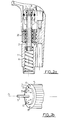
- a sampling and dosing pipette in accordance with the object of the invention will firstly be described in connection with FIG. 2a.
- the sampling and metering pipette which is the subject of the invention comprises, in a similar manner to the pipette of the prior art, as shown in FIG. 1, a pipette body 1 with display of the sampling volume, an adjusting screw 2 meshing with means for displaying the sampling volume, the adjusting screw being secured to a knurled button 3 to allow adjustment of the volume of a sampling chamber formed by a piston 4 secured to a central rod 5.
- the piston 4 is movable in the pipette body 1 on action of the central rod and reaction of a return spring 6.
- the central rod on reaction of the return spring 6 abuts at the end of the adjustment screw 2 comprising the knurled button 3, the stop is advantageously formed by a brake screw 7 for adjustment zero the volume of the sample chamber.
- the brake screw 7 is adjustable in the translational position relative to the end of the adjustment screw 2 and to the knurled knob 3 by a rotational movement for example.
- the brake screw 7 may comprise a threaded element 70 engaged in a thread provided in a housing of the knurled button 3.
- a friction element 71 forming a brake against the wall of the housing is also provided.
- mechanical means 72 are arranged on the external face of the threaded element 70, external face perpendicular to the axis ⁇ of the mechanical means of the threaded element constituting the worm 7.
- the mechanical means 72 arranged on the external face of the threaded element 70, face perpendicular to the axis of the mechanical means of the threaded element 70, can advantageously consist in a plurality of holes arranged for example in a circular arrangement on the above-mentioned external face. These holes are intended to allow the adjustment of the adjusting brake screw 7, by means of a tool specially adapted for this purpose, which will be described later in the description.
- the friction element 71 forming a brake can advantageously be disposed between the external face of the threaded element comprising the above-mentioned mechanical means 72 and a thread intended to be engaged in the thread of the housing of the knurled button 3 as described above.
- the friction element 71 can advantageously be constituted by a rubber ring for example or a ring made of a flexible material, allowing the locking of the threaded element relative to the knurled button 3 in the absence of any setting torque. in rotation exerted on the threaded element 70.
- the actuation of the knurled button 3 by the operator allows the operator to adjust the stroke of the central rod 5 and of the piston 4 and ultimately the choice of sampling volume defined by the stroke of the piston 4 in the body of pipette 1, stroke between the rest position of the piston 4 and the end of the pipette body 1 not shown in the drawing.
- the adjustment of the stroke of the piston and of the central rod 5 is thus carried out by screwing the adjusting screw 2, by means of the knurled button 3, relative to the pipette body 1, the assembly constituted by the knurled button 3, the adjusting screw 2, the central rod 5 and the piston 4 thus moving in translation along the longitudinal axis of symmetry of the pipette.
- the adjusting screw 2 meshing with the means for displaying the sampling volume, this volume is displayed directly in a window provided in the pipette body.
- the zero adjustment of the sampling volume can be obtained by adjusting the relative position of the stop adjustable in position 7, relative to the knurled knob 3 or adjusting screw 2.
- the choice and display of the sampling volume having been carried out by the operator, as described above, he can then actuate the central rod 5 by means of the push button 50, so as to bring the piston 4 into abutment against the end of the body pipette not shown in Figure 1.
- the res recall spell 6 then allows, when the effort on the push button 50 is removed by the operator, the return of the assembly constituted by the piston 4 and the central rod 5 to its initial position, the removal and dosing of the substance to be sampled being thus carried out.
- the volume of the sampling chamber is then adjusted to a value corresponding to a non-zero volume of sampling.
- a plurality of samples of the aforementioned volume of a reference substance can then be taken.
- a consistency test of the plurality of the abovementioned samples can then be carried out.
- An average of the calculated values of the volumes of the plurality of abovementioned samples can then be taken, this average making it possible to define an average value of the volume of samples.
- a new adjustment of the adjustment brake screw 7 is then carried out, the brake screw 7 then being rotated by a number of turns corresponding in value and as a sign of the difference between the value of the volume displayed by the means d display of the pipette body 1 and the average value of the abovementioned sample volume. It is understood that the adjustment of a number of turns corresponding in value and in sign to the difference between the value of the volume displayed and the aforementioned average value, can consist of a fraction of turns of screwing of the brake screw d 'precisely 7.
- the pipette following the step of carrying out the new adjustment of the adjusting brake screw 7, can advantageously be subjected to a control by multiple samples allowing either the acceptance of the pipette as a calibrated pipette, or the resumption of the process the previous step, step consisting in carrying out an average of the values of the volumes of the plurality of withdrawals.
- the consistency test may consist in admitting each of the samples forming the plurality of samples if the latter is included in a dispersion range determined with respect to a reference value.
- the values of the volumes of the plurality of multiple samples can advantageously be calculated by gravimetry.
- the reference substance can consist of any non-volatile substance.
- the pipette can be subjected to a calibration correction in accordance with the steps previously described in the description, steps consisting in carrying out, following a consistency test of the plurality of abovementioned samples, an average of these samples, then in carrying out a new adjustment of the adjustment brake screw 7, of a corresponding number of turns in value and in sign the difference between the value of the displayed volume and the average value displayed.
- the device which is the subject of the invention comprises at least means denoted 100 for driving the brake screw 7 and the knurled knob 3.
- Means denoted 300 for control are also provided, so as to allow control means 100 for driving the brake screw 7 and the knurled button 3.
- the means 100 for driving the brake screw 7 may advantageously include lugs 1020 intended to be mechanically coupled to the mechanical means 72 provided on the external face of the threaded element 70. These lugs allow the application of a torque for rotating the threaded element 70 constituting the brake screw 7.
- a lug pin 102 can be formed by the head of the body of rod 2101 in which the central rod 5 is engaged.
- the rod body 2101 can advantageously be mounted movable in rotation relative to a part with ball bearing 2102.
- the latter to constitute the drive means of the button knurled 3 , may further comprise lugs 2120 intended to come to engage in corresponding orifices denoted 31, 32 of the knurled button 3, in order to immobilize or drive the knurled button 3, with the part 2102, prior to an operation of adjustment, by screwing or unscrewing the brake screw 7.
- the drive means 100 may also comprise a drive motor 101 coupled by a clutch transmission of conventional type by belt by example, to the stem body 2101 and to the piece 2102.
- control means 300 of the drive means 100 of the brake screw can be constituted by a microcomputer, provided with its peripherals.
- Peripherals are understood, of course, permanent memory of the memory type with magnetic support, intercom keyboard with an operator and display monitor, allowing interactive dialogue between the operator and the entire system.
- the implementation of the calibration method, object of the invention, using the device as shown in Figure 4 will now be described.
- the pipette having been brought into position, vis-à-vis respectively of the lugs of the lug pin 102, of the lugs 2120 of the head of the part 2102, firstly, the volume of the sampling chamber is adjusted to zero by means of the knurled knob 3, by means of the motor 101 and the lugs 2120 of part 2102, the latter having the object of driving the knurled knob 3.
- the adjusting brake screw 7 is then actuated by means of the pin 102 with pins 1020, for substantially canceling the stroke of the piston.
- the minimum sample volume noted Vo-Vm corresponding to the position m of the brake screw 7 screwed at the maximum in its housing formed in the knurled button 3, for a volume Vo substantially zero, makes it possible to define a stroke of the piston substantially zero.
- the volume of the sampling chamber is adjusted by rotating the knurled button 3, by means of the motor 101 and of the part 2102 and of the lugs 2120, in order to define an average value of the sampling volume.
- a new adjustment of the adjustment brake screw 7 is carried out by rotation thereof, by means of the motor 101 and the lug pin 1020, by a number of turns corresponding in value and in sign, to l difference between the value of the volume displayed by the display means of the pipette body 1 and the average value of the abovementioned sample volume.
Landscapes
- Health & Medical Sciences (AREA)
- Clinical Laboratory Science (AREA)
- Chemical & Material Sciences (AREA)
- Chemical Kinetics & Catalysis (AREA)
- Sampling And Sample Adjustment (AREA)
- Devices For Use In Laboratory Experiments (AREA)
- Automatic Analysis And Handling Materials Therefor (AREA)
- Investigating Or Analysing Biological Materials (AREA)
Priority Applications (1)
| Application Number | Priority Date | Filing Date | Title |
|---|---|---|---|
| AT87402678T ATE97347T1 (de) | 1986-11-27 | 1987-11-26 | Dosierungs- und probenpipette;verfahren und vorrichtung fuer deren kalibrieren. |
Applications Claiming Priority (2)
| Application Number | Priority Date | Filing Date | Title |
|---|---|---|---|
| FR8616574 | 1986-11-27 | ||
| FR8616574A FR2607407B1 (fr) | 1986-11-27 | 1986-11-27 | Procede et dispositif de calibrage d'une pipette de prelevement et de dosage |
Publications (2)
| Publication Number | Publication Date |
|---|---|
| EP0272963A1 true EP0272963A1 (de) | 1988-06-29 |
| EP0272963B1 EP0272963B1 (de) | 1993-11-18 |
Family
ID=9341292
Family Applications (1)
| Application Number | Title | Priority Date | Filing Date |
|---|---|---|---|
| EP87402678A Expired - Lifetime EP0272963B1 (de) | 1986-11-27 | 1987-11-26 | Dosierungs- und Probenpipette;Verfahren und Vorrichtung für deren Kalibrieren |
Country Status (6)
| Country | Link |
|---|---|
| US (1) | US4790176A (de) |
| EP (1) | EP0272963B1 (de) |
| JP (1) | JPS63141650A (de) |
| AT (1) | ATE97347T1 (de) |
| DE (1) | DE3788198T2 (de) |
| FR (1) | FR2607407B1 (de) |
Families Citing this family (22)
| Publication number | Priority date | Publication date | Assignee | Title |
|---|---|---|---|---|
| FI87740C (fi) * | 1990-05-04 | 1994-04-08 | Biohit Oy | Pipett |
| US5138868A (en) * | 1991-02-13 | 1992-08-18 | Pb Diagnostic Systems, Inc. | Calibration method for automated assay instrument |
| DE4209620C1 (de) * | 1992-03-25 | 1993-12-16 | Eppendorf Geraetebau Netheler | Verfahren zur Korrektur des Volumenfehlers ïV bei einem Pipettiersystem |
| US5460709A (en) * | 1993-06-21 | 1995-10-24 | Helena Laboratories Corporation | Automatic electrophoresis method and apparatus |
| US5370347A (en) * | 1993-07-07 | 1994-12-06 | Helena Laboratories Corporation | Support system for an equipment housing |
| EP1296763B1 (de) * | 2000-06-26 | 2016-05-11 | Vistalab Technologies, Inc. | Handgehaltene pipette |
| US6749812B2 (en) | 2000-06-26 | 2004-06-15 | Vistalab Technologies | Automatic pipette detipping |
| EP1296761A2 (de) * | 2000-06-26 | 2003-04-02 | Vistalab Technologies, Inc. | Verbesserte handgehaltene pipette |
| EP1191312A3 (de) * | 2000-09-21 | 2004-12-22 | Tecan Trading AG | System und Verfahren zur Optimierung der Parameter von Flüssigkeitshandhabungsinstrumenten |
| JP4148894B2 (ja) | 2001-10-16 | 2008-09-10 | マトリックス・テクノロジイズ・コーポレーション | 手持ち式ピペット |
| US7514270B2 (en) | 2002-04-12 | 2009-04-07 | Instrumentation Laboratory Company | Immunoassay probe |
| US7284454B2 (en) | 2004-05-27 | 2007-10-23 | Matrix Technologies Corporation | Hand held pipette |
| US20060027033A1 (en) * | 2002-10-16 | 2006-02-09 | Richard Cote | Hand-held pipette employing voice recognition control |
| US7976793B2 (en) * | 2003-11-27 | 2011-07-12 | Gilson S.A.S. | Electronic pipette |
| FR2862889B1 (fr) * | 2003-11-27 | 2006-09-22 | Gilson Sas | Pipette a main pour le prelevement d'un echantillon liquide sans derive de temperature |
| EP1714116B1 (de) | 2004-02-06 | 2016-06-29 | Seyonic SA | Pipetten-verifikationseinrichtung und pipette |
| US8211386B2 (en) | 2004-06-08 | 2012-07-03 | Biokit, S.A. | Tapered cuvette and method of collecting magnetic particles |
| DE102005033378B4 (de) * | 2005-07-16 | 2012-05-31 | Eppendorf Ag | Kolbenhubpipette |
| EP1887330B1 (de) * | 2006-08-11 | 2009-11-18 | Biohit Oyj | Testverfahren für Pipetten |
| USD620602S1 (en) | 2008-01-03 | 2010-07-27 | Vistalab Technologies, Inc. | Pipette |
| JP5657861B2 (ja) * | 2008-12-30 | 2015-01-21 | 光陽化成有限会社 | マイクロピペット装置 |
| CN114222629B (zh) * | 2019-08-16 | 2023-11-14 | 立洋有限公司 | 移液管的吸入容量校正机构、移液管及其校正方法 |
Citations (4)
| Publication number | Priority date | Publication date | Assignee | Title |
|---|---|---|---|---|
| EP0009013A1 (de) * | 1978-09-04 | 1980-03-19 | Lkb Clinicon Aktiebolag | Pipettier- und Dosiervorrichtung |
| EP0014120A1 (de) * | 1979-01-19 | 1980-08-06 | Marteau d'Autry, Eric | Pipette mit positiver Verstellung |
| EP0067605A1 (de) * | 1981-06-17 | 1982-12-22 | Labsystems Oy | Pipette |
| DE3137423A1 (de) * | 1981-09-19 | 1983-03-31 | Rudolf Brand GmbH & Co, 6980 Wertheim | "mikroliterpipette" |
Family Cites Families (13)
| Publication number | Priority date | Publication date | Assignee | Title |
|---|---|---|---|---|
| US3343539A (en) * | 1964-10-22 | 1967-09-26 | Moorhouse Turkey Hatchery Inc | Piston type artificial insemination syringe having stroke adjusting means |
| US3613952A (en) * | 1970-04-23 | 1971-10-19 | Cole Parmer Instr Co | Fluid dispenser with adjustable stroke piston and register |
| DE2319175A1 (de) * | 1973-04-16 | 1974-10-31 | Oxford Lab | Detail-kolbenpipette |
| DE2330499A1 (de) * | 1973-06-15 | 1975-01-09 | Boepple & Co Kg | Justieranlage fuer pipetten und bueretten |
| SU542547A1 (ru) * | 1974-09-12 | 1977-01-15 | Институт Биохимии И Физиологии Микроорганизмов Ан Ссср | Пипетка |
| US4098125A (en) * | 1977-03-30 | 1978-07-04 | Lee Thomas E | Adjustable volume pipetting device |
| US4096750A (en) * | 1977-06-15 | 1978-06-27 | Oxford Laboratories Inc. | Hand-held micropipettor with fluid transfer volume adjustment mechanism |
| US4165646A (en) * | 1978-07-26 | 1979-08-28 | Shapiro Justin J | Adjustable micro-dispensing liquid pipet |
| US4250755A (en) * | 1979-10-22 | 1981-02-17 | Drummond Scientific Co. | Pipette |
| FR2473124A1 (fr) * | 1980-01-04 | 1981-07-10 | Marteau D Autry Eric | Dispositif de prelevement et de distribution de volumes reglables de liquides, a affichage numerique |
| US4501163A (en) * | 1983-08-30 | 1985-02-26 | Macdermott Bruce R | Adjustable micro-dispensing liquid pipet |
| US4671123A (en) * | 1984-02-16 | 1987-06-09 | Rainin Instrument Co., Inc. | Methods and apparatus for pipetting and/or titrating liquids using a hand held self-contained automated pipette |
| US4672857A (en) * | 1985-09-10 | 1987-06-16 | Labindustries, Inc. | Liquid microdispenser |
-
1986
- 1986-11-27 FR FR8616574A patent/FR2607407B1/fr not_active Expired - Lifetime
- 1986-12-16 US US06/942,392 patent/US4790176A/en not_active Expired - Lifetime
-
1987
- 1987-11-11 JP JP62285149A patent/JPS63141650A/ja active Granted
- 1987-11-26 EP EP87402678A patent/EP0272963B1/de not_active Expired - Lifetime
- 1987-11-26 DE DE3788198T patent/DE3788198T2/de not_active Expired - Lifetime
- 1987-11-26 AT AT87402678T patent/ATE97347T1/de not_active IP Right Cessation
Patent Citations (4)
| Publication number | Priority date | Publication date | Assignee | Title |
|---|---|---|---|---|
| EP0009013A1 (de) * | 1978-09-04 | 1980-03-19 | Lkb Clinicon Aktiebolag | Pipettier- und Dosiervorrichtung |
| EP0014120A1 (de) * | 1979-01-19 | 1980-08-06 | Marteau d'Autry, Eric | Pipette mit positiver Verstellung |
| EP0067605A1 (de) * | 1981-06-17 | 1982-12-22 | Labsystems Oy | Pipette |
| DE3137423A1 (de) * | 1981-09-19 | 1983-03-31 | Rudolf Brand GmbH & Co, 6980 Wertheim | "mikroliterpipette" |
Also Published As
| Publication number | Publication date |
|---|---|
| DE3788198D1 (de) | 1993-12-23 |
| JPH0349616B2 (de) | 1991-07-30 |
| JPS63141650A (ja) | 1988-06-14 |
| FR2607407A1 (fr) | 1988-06-03 |
| EP0272963B1 (de) | 1993-11-18 |
| US4790176A (en) | 1988-12-13 |
| FR2607407B1 (fr) | 1991-08-02 |
| ATE97347T1 (de) | 1993-12-15 |
| DE3788198T2 (de) | 1994-06-16 |
Similar Documents
| Publication | Publication Date | Title |
|---|---|---|
| EP0272963B1 (de) | Dosierungs- und Probenpipette;Verfahren und Vorrichtung für deren Kalibrieren | |
| EP0391757B1 (de) | Vorrichtung zur Nacheichung einer Brillenglasscheifmaschine zum Ausgleich der Schleifscheibenabnutzung | |
| US4141250A (en) | Plural piston, adjustable diluting device having a volume indicator assembly | |
| FR2737569A3 (fr) | Microtome a cryostat | |
| EP0032098B1 (de) | Vorrichtung zum Entnehmen und Wiederabgeben wählbarer Flüssigkeitsmengen mit einer numerischen Anzeige | |
| EP0014120B1 (de) | Pipette mit positiver Verstellung | |
| FR2658328A1 (fr) | Barillet d'objectif zoom a commande electrique. | |
| EP3043913A1 (de) | Probenahmepipette mit verbesserter vorrichtung zur anpassung und anzeige einer zu entnehmenden menge | |
| EP3136071A1 (de) | Kalibriervorrichtung und -verfahren einer höhenmessvorrichtung | |
| EP0873582A1 (de) | Tragbares werkzeug zum crimpen von kontaktstiften an elektrischen leitern | |
| EP0236371B1 (de) | Mikrometer mit numerischer darstellung | |
| EP0260583A1 (de) | Taster zur Dimensionsmessung | |
| EP2981358B1 (de) | Pipettiersystem mit verbesserter steuerung und volumeneinstellung | |
| CH649379A5 (fr) | Appareil de mesure d'alesages. | |
| CA2622094A1 (fr) | Procede et dispositif de reglage de la profondeur d'emmanchement d'un outil dans un porte-outil | |
| FR2680711A1 (fr) | Procede pour la flexion permanente de corps deformables. | |
| EP0360693B1 (de) | Vorrichtung zur Messung der Festigkeit eines verformbaren Gegenstandes | |
| US6453742B1 (en) | System and method for calibrating semiconductor processing equipment | |
| WO2017182049A1 (fr) | Accessoire de centrage d'outils sur une machine d'usinage, procede de centrage et dispositif d'aide au centrage comprenant un tel accessoire | |
| FR2573208A1 (fr) | Dispositif de pompe a mercure destine a la determination de gaz contenus dans les echantillons de roche | |
| WO2004055502A2 (fr) | Procede de mesure d'une quantite de photons proportionnelle a la quantite de photons recus par l'objet et dispositif associe | |
| FR2513376A1 (fr) | Dispositif de pipetage automatique | |
| EP0855575B1 (de) | Messwertgebervorrichtung, insbesondere zum Ermitteln der räumlichen Lage eines Objekts, wie z.B. der Lage einer Fahrzeugwindschutzscheibe relativ zum Fahrzeug | |
| EP1099304B1 (de) | Vorrichtung zur automatischen regelung einer komponente von einer elektronischen karte, insbesondere eines potentiometers | |
| FR2673999A1 (fr) | Dispositif de reglage d'une commande d'orientation d'un systeme optique de projecteur, en particulier pour vehicule automobile. |
Legal Events
| Date | Code | Title | Description |
|---|---|---|---|
| PUAI | Public reference made under article 153(3) epc to a published international application that has entered the european phase |
Free format text: ORIGINAL CODE: 0009012 |
|
| AK | Designated contracting states |
Kind code of ref document: A1 Designated state(s): AT BE CH DE ES GB IT LI NL SE |
|
| 17P | Request for examination filed |
Effective date: 19880816 |
|
| 17Q | First examination report despatched |
Effective date: 19891204 |
|
| GRAA | (expected) grant |
Free format text: ORIGINAL CODE: 0009210 |
|
| AK | Designated contracting states |
Kind code of ref document: B1 Designated state(s): AT BE CH DE ES GB IT LI NL SE |
|
| PG25 | Lapsed in a contracting state [announced via postgrant information from national office to epo] |
Ref country code: IT Free format text: LAPSE BECAUSE OF FAILURE TO SUBMIT A TRANSLATION OF THE DESCRIPTION OR TO PAY THE FEE WITHIN THE PRESCRIBED TIME-LIMIT;WARNING: LAPSES OF ITALIAN PATENTS WITH EFFECTIVE DATE BEFORE 2007 MAY HAVE OCCURRED AT ANY TIME BEFORE 2007. THE CORRECT EFFECTIVE DATE MAY BE DIFFERENT FROM THE ONE RECORDED. Effective date: 19931118 Ref country code: AT Effective date: 19931118 Ref country code: SE Effective date: 19931118 Ref country code: NL Effective date: 19931118 |
|
| REF | Corresponds to: |
Ref document number: 97347 Country of ref document: AT Date of ref document: 19931215 Kind code of ref document: T |
|
| PG25 | Lapsed in a contracting state [announced via postgrant information from national office to epo] |
Ref country code: LI Effective date: 19931130 Ref country code: CH Effective date: 19931130 Ref country code: BE Effective date: 19931130 |
|
| GBT | Gb: translation of ep patent filed (gb section 77(6)(a)/1977) |
Effective date: 19931117 |
|
| REF | Corresponds to: |
Ref document number: 3788198 Country of ref document: DE Date of ref document: 19931223 |
|
| PG25 | Lapsed in a contracting state [announced via postgrant information from national office to epo] |
Ref country code: ES Free format text: LAPSE BECAUSE OF FAILURE TO SUBMIT A TRANSLATION OF THE DESCRIPTION OR TO PAY THE FEE WITHIN THE PRESCRIBED TIME-LIMIT Effective date: 19940228 |
|
| NLV1 | Nl: lapsed or annulled due to failure to fulfill the requirements of art. 29p and 29m of the patents act | ||
| BERE | Be: lapsed |
Owner name: MARTEAU D'AUTRY ERIC Effective date: 19931130 |
|
| REG | Reference to a national code |
Ref country code: CH Ref legal event code: PL |
|
| PLBE | No opposition filed within time limit |
Free format text: ORIGINAL CODE: 0009261 |
|
| STAA | Information on the status of an ep patent application or granted ep patent |
Free format text: STATUS: NO OPPOSITION FILED WITHIN TIME LIMIT |
|
| 26N | No opposition filed | ||
| REG | Reference to a national code |
Ref country code: GB Ref legal event code: IF02 |
|
| REG | Reference to a national code |
Ref country code: GB Ref legal event code: 732E |
|
| PGFP | Annual fee paid to national office [announced via postgrant information from national office to epo] |
Ref country code: GB Payment date: 20061122 Year of fee payment: 20 |
|
| PGFP | Annual fee paid to national office [announced via postgrant information from national office to epo] |
Ref country code: DE Payment date: 20061125 Year of fee payment: 20 |
|
| REG | Reference to a national code |
Ref country code: GB Ref legal event code: PE20 |
|
| PG25 | Lapsed in a contracting state [announced via postgrant information from national office to epo] |
Ref country code: GB Free format text: LAPSE BECAUSE OF EXPIRATION OF PROTECTION Effective date: 20071125 |