EP0272963A1 - Sampling and dosing pipette; process and device for its calibration - Google Patents
Sampling and dosing pipette; process and device for its calibration Download PDFInfo
- Publication number
- EP0272963A1 EP0272963A1 EP87402678A EP87402678A EP0272963A1 EP 0272963 A1 EP0272963 A1 EP 0272963A1 EP 87402678 A EP87402678 A EP 87402678A EP 87402678 A EP87402678 A EP 87402678A EP 0272963 A1 EP0272963 A1 EP 0272963A1
- Authority
- EP
- European Patent Office
- Prior art keywords
- volume
- pipette
- sampling
- screw
- brake screw
- Prior art date
- Legal status (The legal status is an assumption and is not a legal conclusion. Google has not performed a legal analysis and makes no representation as to the accuracy of the status listed.)
- Granted
Links
Images


Classifications
-
- B—PERFORMING OPERATIONS; TRANSPORTING
- B01—PHYSICAL OR CHEMICAL PROCESSES OR APPARATUS IN GENERAL
- B01L—CHEMICAL OR PHYSICAL LABORATORY APPARATUS FOR GENERAL USE
- B01L3/00—Containers or dishes for laboratory use, e.g. laboratory glassware; Droppers
- B01L3/02—Burettes; Pipettes
- B01L3/021—Pipettes, i.e. with only one conduit for withdrawing and redistributing liquids
- B01L3/0217—Pipettes, i.e. with only one conduit for withdrawing and redistributing liquids of the plunger pump type
- B01L3/0224—Pipettes, i.e. with only one conduit for withdrawing and redistributing liquids of the plunger pump type having mechanical means to set stroke length, e.g. movable stops
-
- B—PERFORMING OPERATIONS; TRANSPORTING
- B01—PHYSICAL OR CHEMICAL PROCESSES OR APPARATUS IN GENERAL
- B01L—CHEMICAL OR PHYSICAL LABORATORY APPARATUS FOR GENERAL USE
- B01L2300/00—Additional constructional details
- B01L2300/02—Identification, exchange or storage of information
- B01L2300/025—Displaying results or values with integrated means
- B01L2300/026—Drum counters
Definitions
- the present invention relates to a method and a device for calibrating a sampling and dosing pipette as well as to a pipette allowing a fully automated implementation of the method which is the subject of the invention.
- the sampling and dosing pipettes currently available on the market comprise a pipette body 1 allowing the display of the sampling volume.
- the sampling volume is formed by a piston 4 secured to a central rod 5, the piston being movable in the pipette body 1 upon action of the central rod and reaction of a return spring 6.
- An axial adjustment screw 2 meshes display means 20 of the sampling volume, the adjusting screw being secured to a knurled knob 3 allowing the adjustment of the piston stroke in the pipette body.
- the central rod 5, and the piston on reaction of the return spring normally comes into abutment with an adjustable stop in position 7 at the end of the knurled button 3 in order to allow the zero stroke of the central rod 5 to be adjusted. and the piston, and therefore the sample volume.
- this calibration consisting in fact of setting or adjusting the zero of the sample volume.
- the aforementioned calibration operations can hardly be carried out except manually, appreciably, and the production on an industrial scale of such types of pipettes. implies, prior to their placing on the market, the implementation of a calibration station costing labor and equipment, in order to ensure sufficient production.
- the essentially manual nature of the abovementioned calibration operation cannot make it possible to completely avoid errors or faults in adjustment or calibration, precisely because of the human factor which is inevitably a source of errors and imprecision. , the reduction of this type of error requiring for example additional statistical control operations or the like.
- the object of the present invention is to remedy the aforementioned drawbacks by implementing a method and a device for calibrating a sampling and dosing pipette as well as a pipette specially adapted for fully automated calibration.
- Another object of the present invention is the implementation of a method and a device for calibrating a sampling and dosing pipette, in which human intervention is substantially eliminated, the method being carried out in an automated manner. using the device object of the invention.
- Another object of the present invention is also the implementation of a method and a device for calibrating a sampling and dosing pipette allowing very high precision and very high homogeneity to be obtained. calibration on very large batches of pipettes subjected to the process.
- the pipette which is the subject of the invention is remarkable in that the central rod, on reaction of the return spring, abuts at the end of the adjustment screw comprising the knurled button, the stop is formed by a brake screw zero volume adjustment of the sampling chamber, said brake screw being adjustable in translation position relative to the end of the adjusting screw and to the knurled knob by a rotational movement.
- the method and the device for calibrating a sampling and dosing pipette, object of the invention are remarkable in that they consist or successively lead to adjusting the volume of the sampling chamber to zero by means of the knurled button. , then actuate the adjustment brake screw to appreciably cancel the stroke of the piston, adjust the volume of the sampling chamber to a low non-zero volume, then taking a plurality of samples of the aforementioned volume of a reference substance, carrying out following a consistency test of the plurality of aforementioned samples an average of the calculated values of the volumes of the plurality of the aforementioned samples, making a new adjustment of the brake adjusting screw for a number of revolutions corresponding in value and as a sign of the difference between the value of the volume displayed and the aforementioned average value.
- the invention finds application for the adjustment or calibration of devices, sampling or pipettes according to the invention.
- a sampling and dosing pipette in accordance with the object of the invention will firstly be described in connection with FIG. 2a.
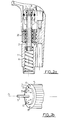
- the sampling and metering pipette which is the subject of the invention comprises, in a similar manner to the pipette of the prior art, as shown in FIG. 1, a pipette body 1 with display of the sampling volume, an adjusting screw 2 meshing with means for displaying the sampling volume, the adjusting screw being secured to a knurled button 3 to allow adjustment of the volume of a sampling chamber formed by a piston 4 secured to a central rod 5.
- the piston 4 is movable in the pipette body 1 on action of the central rod and reaction of a return spring 6.
- the central rod on reaction of the return spring 6 abuts at the end of the adjustment screw 2 comprising the knurled button 3, the stop is advantageously formed by a brake screw 7 for adjustment zero the volume of the sample chamber.
- the brake screw 7 is adjustable in the translational position relative to the end of the adjustment screw 2 and to the knurled knob 3 by a rotational movement for example.
- the brake screw 7 may comprise a threaded element 70 engaged in a thread provided in a housing of the knurled button 3.
- a friction element 71 forming a brake against the wall of the housing is also provided.
- mechanical means 72 are arranged on the external face of the threaded element 70, external face perpendicular to the axis ⁇ of the mechanical means of the threaded element constituting the worm 7.
- the mechanical means 72 arranged on the external face of the threaded element 70, face perpendicular to the axis of the mechanical means of the threaded element 70, can advantageously consist in a plurality of holes arranged for example in a circular arrangement on the above-mentioned external face. These holes are intended to allow the adjustment of the adjusting brake screw 7, by means of a tool specially adapted for this purpose, which will be described later in the description.
- the friction element 71 forming a brake can advantageously be disposed between the external face of the threaded element comprising the above-mentioned mechanical means 72 and a thread intended to be engaged in the thread of the housing of the knurled button 3 as described above.
- the friction element 71 can advantageously be constituted by a rubber ring for example or a ring made of a flexible material, allowing the locking of the threaded element relative to the knurled button 3 in the absence of any setting torque. in rotation exerted on the threaded element 70.
- the actuation of the knurled button 3 by the operator allows the operator to adjust the stroke of the central rod 5 and of the piston 4 and ultimately the choice of sampling volume defined by the stroke of the piston 4 in the body of pipette 1, stroke between the rest position of the piston 4 and the end of the pipette body 1 not shown in the drawing.
- the adjustment of the stroke of the piston and of the central rod 5 is thus carried out by screwing the adjusting screw 2, by means of the knurled button 3, relative to the pipette body 1, the assembly constituted by the knurled button 3, the adjusting screw 2, the central rod 5 and the piston 4 thus moving in translation along the longitudinal axis of symmetry of the pipette.
- the adjusting screw 2 meshing with the means for displaying the sampling volume, this volume is displayed directly in a window provided in the pipette body.
- the zero adjustment of the sampling volume can be obtained by adjusting the relative position of the stop adjustable in position 7, relative to the knurled knob 3 or adjusting screw 2.
- the choice and display of the sampling volume having been carried out by the operator, as described above, he can then actuate the central rod 5 by means of the push button 50, so as to bring the piston 4 into abutment against the end of the body pipette not shown in Figure 1.
- the res recall spell 6 then allows, when the effort on the push button 50 is removed by the operator, the return of the assembly constituted by the piston 4 and the central rod 5 to its initial position, the removal and dosing of the substance to be sampled being thus carried out.
- the volume of the sampling chamber is then adjusted to a value corresponding to a non-zero volume of sampling.
- a plurality of samples of the aforementioned volume of a reference substance can then be taken.
- a consistency test of the plurality of the abovementioned samples can then be carried out.
- An average of the calculated values of the volumes of the plurality of abovementioned samples can then be taken, this average making it possible to define an average value of the volume of samples.
- a new adjustment of the adjustment brake screw 7 is then carried out, the brake screw 7 then being rotated by a number of turns corresponding in value and as a sign of the difference between the value of the volume displayed by the means d display of the pipette body 1 and the average value of the abovementioned sample volume. It is understood that the adjustment of a number of turns corresponding in value and in sign to the difference between the value of the volume displayed and the aforementioned average value, can consist of a fraction of turns of screwing of the brake screw d 'precisely 7.
- the pipette following the step of carrying out the new adjustment of the adjusting brake screw 7, can advantageously be subjected to a control by multiple samples allowing either the acceptance of the pipette as a calibrated pipette, or the resumption of the process the previous step, step consisting in carrying out an average of the values of the volumes of the plurality of withdrawals.
- the consistency test may consist in admitting each of the samples forming the plurality of samples if the latter is included in a dispersion range determined with respect to a reference value.
- the values of the volumes of the plurality of multiple samples can advantageously be calculated by gravimetry.
- the reference substance can consist of any non-volatile substance.
- the pipette can be subjected to a calibration correction in accordance with the steps previously described in the description, steps consisting in carrying out, following a consistency test of the plurality of abovementioned samples, an average of these samples, then in carrying out a new adjustment of the adjustment brake screw 7, of a corresponding number of turns in value and in sign the difference between the value of the displayed volume and the average value displayed.
- the device which is the subject of the invention comprises at least means denoted 100 for driving the brake screw 7 and the knurled knob 3.
- Means denoted 300 for control are also provided, so as to allow control means 100 for driving the brake screw 7 and the knurled button 3.
- the means 100 for driving the brake screw 7 may advantageously include lugs 1020 intended to be mechanically coupled to the mechanical means 72 provided on the external face of the threaded element 70. These lugs allow the application of a torque for rotating the threaded element 70 constituting the brake screw 7.
- a lug pin 102 can be formed by the head of the body of rod 2101 in which the central rod 5 is engaged.
- the rod body 2101 can advantageously be mounted movable in rotation relative to a part with ball bearing 2102.
- the latter to constitute the drive means of the button knurled 3 , may further comprise lugs 2120 intended to come to engage in corresponding orifices denoted 31, 32 of the knurled button 3, in order to immobilize or drive the knurled button 3, with the part 2102, prior to an operation of adjustment, by screwing or unscrewing the brake screw 7.
- the drive means 100 may also comprise a drive motor 101 coupled by a clutch transmission of conventional type by belt by example, to the stem body 2101 and to the piece 2102.
- control means 300 of the drive means 100 of the brake screw can be constituted by a microcomputer, provided with its peripherals.
- Peripherals are understood, of course, permanent memory of the memory type with magnetic support, intercom keyboard with an operator and display monitor, allowing interactive dialogue between the operator and the entire system.
- the implementation of the calibration method, object of the invention, using the device as shown in Figure 4 will now be described.
- the pipette having been brought into position, vis-à-vis respectively of the lugs of the lug pin 102, of the lugs 2120 of the head of the part 2102, firstly, the volume of the sampling chamber is adjusted to zero by means of the knurled knob 3, by means of the motor 101 and the lugs 2120 of part 2102, the latter having the object of driving the knurled knob 3.
- the adjusting brake screw 7 is then actuated by means of the pin 102 with pins 1020, for substantially canceling the stroke of the piston.
- the minimum sample volume noted Vo-Vm corresponding to the position m of the brake screw 7 screwed at the maximum in its housing formed in the knurled button 3, for a volume Vo substantially zero, makes it possible to define a stroke of the piston substantially zero.
- the volume of the sampling chamber is adjusted by rotating the knurled button 3, by means of the motor 101 and of the part 2102 and of the lugs 2120, in order to define an average value of the sampling volume.
- a new adjustment of the adjustment brake screw 7 is carried out by rotation thereof, by means of the motor 101 and the lug pin 1020, by a number of turns corresponding in value and in sign, to l difference between the value of the volume displayed by the display means of the pipette body 1 and the average value of the abovementioned sample volume.
Abstract
Description
La présente invention est relative à un procédé et un dispositif de calibrage d'une pipette de prélèvement et de dosage ainsi qu'à une pipette permettant une mise en oeuvre entièrement automatisée du procédé objet de l'invention.The present invention relates to a method and a device for calibrating a sampling and dosing pipette as well as to a pipette allowing a fully automated implementation of the method which is the subject of the invention.
Les pipettes de prélèvement et de dosage actuellement disponibles dans le commerce, ainsi que représenté en figure 1, comportent un corps de pipette 1 permettant l'affichage du volume de prélèvement. Le volume de prélèvement est formé par un piston 4 solidaire d'une tige centrale 5, le piston étant mobile dans le corps de pipette 1 sur action de la tige centrale et réaction d'un ressort de rappel 6. Une vis de réglage axiale 2 engrène des moyens d'affichage 20 du volume de prélèvement, la vis de réglage étant solidaire d'un bouton moleté 3 permettant le réglage de la course du piston dans le corps de pipette. La tige centrale 5, et le piston sur réaction du ressort de rappel, vient normalement en butée d'une butée réglable en position 7 à l'extrémité du bouton moleté 3 afin de permettre le réglage du zéro de la course de la tige centrale 5 et du piston, et, en conséquence, du volume de prélèvement.The sampling and dosing pipettes currently available on the market, as shown in FIG. 1, comprise a pipette body 1 allowing the display of the sampling volume. The sampling volume is formed by a piston 4 secured to a
Pour une description plus détaillée d'une pipette telle que décrite précédemment, on pourra se reporter utilement à la demande de brevet français no 80 00130 déposée le 4 Janvier 1980 au nom de la Demanderesse et intitulée "dispositif de prélèvement et de distribution de volumes réglables de liquides à affichage numérique".For a more detailed description of such pipette described above, reference may be useful in the French patent application No. 80 00130 filed January 4, 1980 on behalf of the Applicant and entitled "sampling device and distribution volumes adjustable liquids with digital display ".
Ce type de pipette a jusqu'à ce jour donné entière satisfaction tant du point de vue de la fiabilité d'utilisation que de la fidélité des mesures ou dosages répétitifs.This type of pipette has so far given complete satisfaction both from the point of view of reliability of use and of the precision of repetitive measurements or dosages.
Cependant, préalablement à la commercialisation de ce type d'appareil, il est nécessaire d'effectuer un calibrage à l'unité, ce calibrage consistant en fait en un réglage ou ajustement du zéro du volume de prélèvement.However, prior to the commercialization of this type of device, it is necessary to perform a unit calibration, this calibration consisting in fact of setting or adjusting the zero of the sample volume.
En raison de la structure propre du système de réglage ou ajustement du zéro du volume de prélèvement, les opérations de calibrage précédemment citées ne peuvent guère être menées à bien que manuellement,sensiblement,et la production à l'échelle industrielle de tels types de pipettes implique, préalablement à leur mise sur le marché, la mise en oeuvre d'un poste de calibrage coûteux en main d'oeuvre et en matériel, en vue d'assurer une production suffisante. En outre, le caractère essentiellement manuel de l'opération de calibrage précitée ne peut permettre de s'affranchir en totalité d'erreurs ou de défauts de réglage ou de calibrae, en raison précisément du facteur humain inévitablement source d'erreurs et d'imprécision, la réduction de ce type d'erreur nécessitant par exemple des opérations de contrôle statistique supplémentaires ou analogues.Due to the specific structure of the zero volume sampling adjustment or adjustment system, the aforementioned calibration operations can hardly be carried out except manually, appreciably, and the production on an industrial scale of such types of pipettes. implies, prior to their placing on the market, the implementation of a calibration station costing labor and equipment, in order to ensure sufficient production. In addition, the essentially manual nature of the abovementioned calibration operation cannot make it possible to completely avoid errors or faults in adjustment or calibration, precisely because of the human factor which is inevitably a source of errors and imprecision. , the reduction of this type of error requiring for example additional statistical control operations or the like.
La présente invention a pour but de remédier aux inconvénients précités par la mise en oeuvre d'un procédé et d'un dispositif de calibrage d'une pipette de prélèvement et de dosage ainsi que d'une pipette spécialement adaptée à un calibrage entièrement automatisé.The object of the present invention is to remedy the aforementioned drawbacks by implementing a method and a device for calibrating a sampling and dosing pipette as well as a pipette specially adapted for fully automated calibration.
Un autre objet de la présente invention est la mise en oeuvre d'un procédé et d'un dispositif de calibrage d'une pipette de prélèvement et de dosage, dans lesquels l'intervention humaine est sensiblement supprimée, le procédé étant conduit de manière automatisée à l'aide du dispositif objet de l'invention.Another object of the present invention is the implementation of a method and a device for calibrating a sampling and dosing pipette, in which human intervention is substantially eliminated, the method being carried out in an automated manner. using the device object of the invention.
Un autre objet de la présente invention est également la mise en oeuvre d'un procédé et d'un dispositif de calibrage d'une pipette de prélèvement et de dosage permettant l'obtention d'une très grande précision et d'une très grande homogénéité de calibrage sur des lots très importants de pipettes soumises au procédé.Another object of the present invention is also the implementation of a method and a device for calibrating a sampling and dosing pipette allowing very high precision and very high homogeneity to be obtained. calibration on very large batches of pipettes subjected to the process.
La pipette objet de l'invention est remarquable en ce que la tige centrale, sur réaction du ressort de rappel, venant en butée au niveau de l'extrémité de la vis de réglage comportant le bouton moleté, la butée est formée par une vis frein d'ajustement du zéro du volume de la chambre de prélèvement, ladite vis frein étant réglable en position de translation par rapport à l'extrémité de la vis de réglage et au bouton moleté par un mouvement de rotation.The pipette which is the subject of the invention is remarkable in that the central rod, on reaction of the return spring, abuts at the end of the adjustment screw comprising the knurled button, the stop is formed by a brake screw zero volume adjustment of the sampling chamber, said brake screw being adjustable in translation position relative to the end of the adjusting screw and to the knurled knob by a rotational movement.
Le procédé et le dispositif de calibrage d'une pipette de prélèvement et de dosage, objet de l'invention, sont remarquables en ce qu'ils consistent ou conduisent successivement à régler le volume de la chambre de prélèvement à zéro au moyen du bouton moleté, puis à actionner la vis frein d'ajustement pour annuler sensiblement la course du piston, à régler le volume de la chambre de prélèvement sur un volume non nul faible, puis à effectuer une pluralité de prélèvements du volume précité d'une substance de référence, à effectuer suite à un test de cohérence de la pluralité de prélèvements précités une moyenne des valeurs calculées des volumes de la pluralité des prélèvements précités, à effectuer un nouvel ajustement de la vis frein d'ajustement d'un nombre de tours correspondant en valeur et en signe à l'écart entre la valeur du volume affiché et la valeur moyenne précitée.The method and the device for calibrating a sampling and dosing pipette, object of the invention, are remarkable in that they consist or successively lead to adjusting the volume of the sampling chamber to zero by means of the knurled button. , then actuate the adjustment brake screw to appreciably cancel the stroke of the piston, adjust the volume of the sampling chamber to a low non-zero volume, then taking a plurality of samples of the aforementioned volume of a reference substance, carrying out following a consistency test of the plurality of aforementioned samples an average of the calculated values of the volumes of the plurality of the aforementioned samples, making a new adjustment of the brake adjusting screw for a number of revolutions corresponding in value and as a sign of the difference between the value of the volume displayed and the aforementioned average value.
L'invention trouve application pour le réglage ou calibrage de dispositifs, de prélèvement ou pipettes conformément à l'invention.The invention finds application for the adjustment or calibration of devices, sampling or pipettes according to the invention.
Elle sera mieux comprise à la lecture de la description et à l'observation des dessins ci-après, dans lesquels :
- - la figure 1 représente, en coupe selon un plan longitudinal de symétrie, une vue relative à une pipette de prélèvement et dosage de l'art antérieur,
- - la figure 2a représente, en coupe selon un plan longitudinal de symétrie, une vue relative à une pipette de prélèvement et dosage conformément à la présente invention,
- - la figure 2b représente une vue partielle de la figure 2a,
- - la figure 3 représente un schéma illustratif du procédé de calibrage, objet de l'invention,
- - la figure 4 représente en coupe un schéma illustratif d'un dispositif de calibrage, conformément à la présente invention, le dispositif étant avantageusement susceptible de permettre la mise en oeuvre du procédé objet de l'invention.
- FIG. 1 represents, in section along a longitudinal plane of symmetry, a view relating to a prior art sampling and dosing pipette,
- FIG. 2a represents, in section along a longitudinal plane of symmetry, a view relating to a sampling and dosing pipette according to the present invention,
- FIG. 2b represents a partial view of FIG. 2a,
- FIG. 3 represents an illustrative diagram of the calibration process, object of the invention,
- - Figure 4 shows in section an illustrative diagram of a calibration device, in accordance with the present invention, the device being advantageously capable of allowing the implementation of the method of the invention.
Une pipette de prélèvement et de dosage conformément à l'objet de l'invention sera tout d'abord décrite en liaison avec la figure 2a.A sampling and dosing pipette in accordance with the object of the invention will firstly be described in connection with FIG. 2a.
Selon la figure précitée, la pipette de prélèvement et de dosage objet de l'invention comprend, de manière analogue à la pipette de l'art antérieur, telle que représentée en figure 1, un corps de pipette 1 à affichage du volume de prélèvement, une vis de réglage 2 engrenant des moyens d'affichage du volume de prélèvement, la vis de réglage étant solidaire d'un bouton moleté 3 pour permettre le réglage du volume d'une chambre de prélèvement formée d'un piston 4 solidaire d'une tige centrale 5. Le piston 4 est mobile dans le corps de pipette 1 sur action de la tige centrale et réaction d'un ressort de rappel 6.According to the above-mentioned figure, the sampling and metering pipette which is the subject of the invention comprises, in a similar manner to the pipette of the prior art, as shown in FIG. 1, a pipette body 1 with display of the sampling volume, an adjusting
Conformément à l'invention, la tige centrale sur réaction du ressort de rappel 6 venant en butée au niveau de l'extrémité de la vis de réglage 2 comportant le bouton moleté 3, la butée est avantageusement formée par une vis frein 7 d'ajustement du zéro du volume de la chambre de prélèvement. La vis frein 7 est réglable en position de translation par rapport à l'extrémité de la vis de réglage 2 et au bouton moleté 3 par un mouvement de rotation par exemple.According to the invention, the central rod on reaction of the return spring 6 abuts at the end of the
Selon un mode de réalisation avantageux, la vis frein 7 peut comprendre un élément fileté 70 engagé dans un taraudage prévu dans un logement du bouton moleté 3. Un élément de friction 71 formant frein contre la paroi du logement est en outre prévu.According to an advantageous embodiment, the
En outre des moyens mécaniques 72 sont disposés sur la face externe de l'élément fileté 70, face externe perpendiculaire à l'axe Δ des moyens mécaniques de l'élément fileté constituant la vis sans fin 7.In addition,
Ainsi qu'il a été représenté de façon non limitative en figure 2b, les moyens mécaniques 72 disposés sur la face externe de l'élément fileté 70, face perpendiculaire à l'axe des moyens mécaniques de l'élément fileté 70, peuvent consister avantageusement en une pluralité de trous disposés par exemple selon un arrangement circulaire sur la face externe précitée. Ces trous sont destinés à permettre l'entraînement de la vis frein 7 d'ajustement, par l'intermédiaire d'un outil spécialement adapté à cet effet, lequel sera décrit ultérieurement dans la description.As shown in a nonlimiting manner in FIG. 2b, the
En outre, l'élément de friction 71 formant frein peut avantageusement être disposé entre la face externe de l'élément fileté comportant des moyens mécaniques 72 précités et un filetage destiné à être engagé dans le taraudage du logement du bouton moleté 3 ainsi que précédemment décrit. L'élément de friction 71 peut, avantageusement, être constitué par un anneau en caoutchouc par exemple ou un anneau en un matériau souple, permettant le blocage de l'élément fileté par rapport au bouton moleté 3 en l'absence de tout couple de mise en rotation exercé sur l'élément fileté 70.In addition, the
Un mode de réalisation avantageux du procédé de calibrage d'une pipette de prélèvement et de dosage conformément à l'invention sera décrit en liaison avec la figure 3.An advantageous embodiment of the method for calibrating a sampling and dosing pipette according to the invention will be described in connection with FIG. 3.
Préalablement à la description du procédé objet de l'invention, un rappel succint du fonctionnement de la pipette telle que représentée en figure 2a par exemple sera tout d'abord effectué.Prior to the description of the process which is the subject of the invention, a brief reminder of the operation of the pipette as shown in FIG. 2a for example will first be made.
L'actionnement du bouton moleté 3 par l'opérateur permet à celui-ci le réglage de la course de la tige centrale 5 et du piston 4 et en définitive le choix du volume de prélèvement défini par la course du piston 4 dans le corps de pipette 1, course comprise entre la position de repos du piston 4 et l'extrémité du corps de pipette 1 non représentée au dessin. Le réglage de la course du piston et de la tige centrale 5 est ainsi effectué par vissage de la vis de réglage 2,par l'intermédiaire du bouton moleté 3, par rapport au corps de pipette 1, l'ensemble constitué par le bouton moleté 3, la vis de réglage 2, la tige centrale 5 et le piston 4 se déplaçant ainsi en translation selon l'axe longitudinal de symétrie de la pipette. En outre, la vis de réglage 2 engrènant les moyens d'affichage du volume de prélèvement, ce volume est affiché directement dans une fenêtre ménagée dans le corps de pipette. On comprendra bien entendu que le réglage du zéro du volume de prélèvement peut être obtenu par le réglage de la position relative de la butée réglable en position 7, par rapport au bouton moleté 3 ou vis de réglage 2. Le choix et l'affichage du volume de prélèvement ayant été effectués par l'opérateur, ainsi que décrit précédemment, celui-ci peut alors actionner la tige centrale 5 par l'intermédiaire du bouton poussoir 50, de façon à amener le piston 4 en butée contre l'extrémité du corps de pipette non représentée en figure 1. Le res sort de rappel 6 permet alors, lors de la suppression de l'effort sur le bouton poussoir 50 par l'opérateur,le retour de l'ensemble constitué par le piston 4 et la tige centrale 5 en sa position initiale, le prélèvement et le dosage de la substance à prélever étant ainsi effectués.The actuation of the
Conformément à un aspect avantageux du procédé objet de l'invention, celui-ci consiste,dans un premier temps, à régler le volume de la chambre de prélèvement à zéro au moyen du bouton moleté 3, puis à actionner la vis frein 7 d'ajustement, pour annuler sensiblement la course du piston. Sur le diagramme représenté en figure 3, on comprendra que pour un réglage du volume de prélèvement noté VO effectué au moyen du bouton moleté 3, le réglage de la vis frein 7 d'ajustement en position, selon l'axe longitudinal du corps de pipette noté Δ, correspondant en fait à un réglage de position de la butée de l'équipage constitué par la tige centrale 5 et le piston 4, permet en fait d'obtenir un réglage effectif du volume de prélèvement VO, compris entre VO + M pour une position extrême saillante de la vis frein 7 par rapport au bouton moleté 3, volume noté VO + M sur le diagramme de la figure 3, et un volume de prélèvement minimum, noté VO - m, correspondant à la position notée m de la vis frein 7, celle-ci étant vissée au maximum dans le logement ménagé à cet effet dans le bouton moleté 3. Pour un choix du volume de prélèvement VO sensiblement nul, celui-ci étant effectué par réglage du bouton moleté 3, la mise en position de la vis frein 7 d'ajustement en position m précédemment définie, permet de définir une course de piston sensiblement nulle.According to an advantageous aspect of the process which is the subject of the invention, it consists, firstly, in adjusting the volume of the sampling chamber to zero by means of the
Conformément au procédé objet de l'invention, le volume de la chambre de prélèvement est ensuite réglé sur une valeur correspondant à un volume non nul de prélèvement. Une pluralité de prélèvements du volume précité d'une substance de référence peut alors être effectuée.In accordance with the process which is the subject of the invention, the volume of the sampling chamber is then adjusted to a value corresponding to a non-zero volume of sampling. A plurality of samples of the aforementioned volume of a reference substance can then be taken.
De manière avantageuse, afin de garantir une grande fiabilité de calibrage du procédé objet de l'invention, un test de cohérence de la pluralité des prélèvements précités peut alors être effectué. Une moyenne des valuers calculée des volumes de la pluralité des prélèvements précités peut alors être effectuée, cette moyenne permettant de définir une valeur moyenne du volume de prélèvement.Advantageously, in order to guarantee high reliability of calibration of the method which is the subject of the invention, a consistency test of the plurality of the abovementioned samples can then be carried out. An average of the calculated values of the volumes of the plurality of abovementioned samples can then be taken, this average making it possible to define an average value of the volume of samples.
Un nouvel ajustement de la vis frein 7 d'ajustement est alors effectué, la vis frein 7 étant alors mue en rotation d'un nombre de tours correspondant en valeur et en signe à l'écart entre la valeur du volume affiché par les moyens d'affichage du corps de pipette 1 et la valeur moyenne du volume de prélèvement précitée. Il est bien entendu que l'ajustement d'un nombre de tours correspondant en valeur et en signe à l'écart entre la valeur du volume affiché et la valeur moyenne précitée, peut consister en une fraction de tours de vissage de la vis frein d'justement 7.A new adjustment of the
Selon une autre caractéristique avantageuse du procédé objet de l'invention précédemment décrit, suite à l'étape consistant à effectuer le nouvel ajustement de la vis frein 7 d'ajustement, la pipette peut avantageusement être soumise à un contrôle par prélèvements multiples permettant soit l'acceptation de la pipette comme pipette calibrée, soit la reprise du procédé à l'étape précédente, étape consistant à effectuer une moyenne des valeurs des volumes de la pluralité des prélèvements.According to another advantageous characteristic of the method which is the subject of the invention described above, following the step of carrying out the new adjustment of the adjusting
Selon une caractéristique avantageuse du procédé de l'invention, le test de cohérence peut consister à admettre chacun des prélèvements formant la pluralité de prélèvements si celui-ci est compris dans une plage de dispersion déterminée par rapport à une valeur de référence. Les valeurs des volumes de la pluralité des prélèvements multiples peuvent avantageusement être calculées par gravimétrie.According to an advantageous characteristic of the method of the invention, the consistency test may consist in admitting each of the samples forming the plurality of samples if the latter is included in a dispersion range determined with respect to a reference value. The values of the volumes of the plurality of multiple samples can advantageously be calculated by gravimetry.
La substance de référence peut être constituée par toute substance non volatile.The reference substance can consist of any non-volatile substance.
Dans le cas où l'acart entre la valeur du volume affiché et la moyenne des valeurs des multiples prélèvements est supérieure à une valeur de tolérance déterminée, la pipette peut être soumise à une correction de calibrage conformément aux étapes précédemment décrites dans la description, étapes consistant à effectuer, suite à un test de cohérence de la pluralité de prélèvements précités, une moyenne de ces prélèvements, puis à effectuer un nouvel ajustement de la vis frein d'ajustement 7, d'un nombre de tours correspondant en valeur et en signe à l'écart entre la valeur du volume affiché et la valeur moyenne affichée.In the case where the difference between the value of the displayed volume and the average of the values of the multiple samples is greater than a determined tolerance value, the pipette can be subjected to a calibration correction in accordance with the steps previously described in the description, steps consisting in carrying out, following a consistency test of the plurality of abovementioned samples, an average of these samples, then in carrying out a new adjustment of the
Un dispositif de calibrage d'une pipette de prélèvement et de dosage selon le procédé objet de l'invention sera maintenant décrit en liaison avec la figure 4.A device for calibrating a sampling and dosing pipette according to the process which is the subject of the invention will now be described in connection with FIG. 4.
Conformément à cette figure, le dispositif objet de l'invention comporte au moins des moyens notés 100 d'entraînement de la vis frein 7 et du bouton moleté 3. Des moyens notés 300 de commande sont en outre prévus, de façon à permettre la commande des moyens 100 d'entraînement de la vis frein 7 et du bouton moleté 3. Les moyens 100 d'entraînement de la vis frein 7 peuvent comporter avantageusement des ergots 1020 destinés à s'accoupler mécaniquement aux moyens mécaniques 72 prévus sur la face externe de l'élément fileté 70. Ces ergots permettent l'application d'un couple de mise en rotation de l'élément fileté 70 constituant la vis frein 7. De manière avantageuse, une broche à ergots 102 peut être constituée par la tête du corps de tige 2101 dans lequel est engagée la tige centrale 5. Le corps de tige 2101 peut, de manière avantageuse, être monté mobile en rotation par rapport à une pièce à roulement à billes 2102. Ce dernier, pour constituer les moyens d'entraînement du bouton moleté 3, peut comporter en outre des ergots 2120 destinés à venir s'engager dans des orifices correspondants notés 31, 32 du bouton moleté 3, afin d'immobiliser ou d'entraîner le bouton moleté 3, avec la pièce 2102, préalablement à une opération de réglage, par vissage ou dévissage de la vis frein 7. Les moyens d'entraînement 100 peuvent en outre, comprendre un moteur d'entraînement 101 couplé par une transmission à embrayage de type classique par courroie par exemple, au corps de tige 2101 et à la pièce 2102.In accordance with this figure, the device which is the subject of the invention comprises at least means denoted 100 for driving the
Ainsi qu'il a été représenté schématiquement en figure 4, les moyens de commande 300 des moyens d'entraînement 100 de la vis frein peuvent être constitués par un microordinateur, muni de ses périphériques. Par périphériques, on entend bien entendu, mémoire permanentes de type mémoire à support magnétique, clavier d'intercommunication avec un opérateur et moniteur d'affichage, permettant un dialogue interactif entre l'opérateur et l'ensemble du système. La mise en oeuvre du procédé de calibrage, objet de l'invention, à l'aide du dispositif tel que représenté en figure 4 sera maintenant décrite. La pipette ayant été amenée en position, vis-à-vis respectivement des ergots de la broche à ergots 102, des ergots 2120 de la tête de la pièce 2102, dans un premier temps, le volume de la chambre de prélèvement est réglé à zéro au moyen du bouton moleté 3, par l'intermédiaire du moteur 101 et des ergots 2120 de la pièce 2102, ces derniers ayant pour objet d'entraîner le bouton moleté 3. La vis frein 7 d'ajustement est ensuite actionnée au moyen de la broche 102 à ergots 1020, pour annuler sensiblement la course du piston. Le volume de prélèvements minimum noté Vo-Vm, correspondant à la position m de la vis frein 7 vissée au maximum dans son logement ménagé dans le bouton moleté 3, pour un volume Vo sensiblement nul, permet de définir une course du piston sensiblement nulle.As shown schematically in Figure 4, the control means 300 of the drive means 100 of the brake screw can be constituted by a microcomputer, provided with its peripherals. Peripherals are understood, of course, permanent memory of the memory type with magnetic support, intercom keyboard with an operator and display monitor, allowing interactive dialogue between the operator and the entire system. The implementation of the calibration method, object of the invention, using the device as shown in Figure 4 will now be described. The pipette having been brought into position, vis-à-vis respectively of the lugs of the
Puis le volume de la chambre de prélèvement est réglé par mise en rotation du bouton moleté 3, par l'intermédiaire du moteur 101 et de la pièce 2102 et des ergots 2120, afin de définir une valeur moyenne du volume de prélèvement.Then the volume of the sampling chamber is adjusted by rotating the
Un nouvel ajustement de la vis frein 7 d'ajustement est effectué par mise en rotation de celle-ci, au moyen du moteur 101 et de la broche à ergots 1020, d'un nombre de tours correspondant en valeur et en signe, à l'écart entre la valeur du volume affiché par les moyens d'affichage du corps de pipette 1 et la valeur moyenne du volume de prélèvement précitée.A new adjustment of the
Cette variante du procédé objet de l'invention précédemment décrite n'est donnée qu'à titre d'exemple non limitatif. Le procédé de calibrage de pipette de prélèvement et de dosage, objet de l'invention et le dispositif permettant la mise en oeuvre de ce procédé, sont particulièrement remarquables en ce qu'ils permettent, moyennant une faible dépense en matériel, un contrôle très précis du calibrage de pipette de prélèvement et de dosage, ainsi qu'une très grande homogénéité de calibrage sur un lot très important de pipettes destinées à la commercialisation.This variant of the process which is the subject of the invention previously described is given only by way of nonlimiting example. The method for calibrating the sampling and dosing pipette, object of the invention and the device allowing the implementation of this method, are particularly remarkable in that they allow, with a low expenditure of material, very precise control. calibration of the sampling and dosing pipette, as well as a very high uniformity of calibration on a very large batch of pipettes intended for marketing.
Claims (10)
- un élément fileté (70) engagé dans un taraudage prévu dans un logement du bouton moleté (3),
- un élément de friction (71), formant frein, contre la paroi dudit logement,
- des moyens mécaniques (72) disposés sur la face externe de l'élément fileté perpendiculaire à l'axe des moyens mécaniques de l'élément fileté constituant la vis frein (7).2. Pipette according to claim 1, characterized in that the brake screw (7) comprises:
- a threaded element (70) engaged in a thread provided in a housing of the knurled button (3),
a friction element (71) forming a brake against the wall of said housing,
- Mechanical means (72) arranged on the external face of the threaded element perpendicular to the axis of the mechanical means of the threaded element constituting the brake screw (7).
- des moyens (100) d'entraînement de la vis frein (7) et du bouton moleté (3),
- des moyens (300) de commande desdits moyens d'entraînement de la vis frein (7) et du bouton moleté 3.7. Device for calibrating a sampling and dosing pipette according to the calibration method of one of claims 3 to 6, characterized in that it comprises at least:
- means (100) for driving the brake screw (7) and the knurled button (3),
- means (300) for controlling said means for driving the brake screw (7) and the knurled button 3.
- un moteur d'entraînement (101),
- une broche à ergots (102), couplée au moteur d'entraînement, lesdits ergots constituent partie mâle des moyens mécaniques de l'élément fileté constituant la vis frein (7),
- une pièce (2102) mobile en rotation autour de la broche à ergots (102), ladite pièce (2102) étant elle-même couplée au moteur d'entraînement (101) et munie d'ergots (2120) destinés à venir s'engager dans des orifices correspondants (31,32) du bouton moleté (3) afin d'actionner celui-ci.8. Device according to claim 7, characterized in that said means (100) for driving the brake screw (7) and the knurled button (3) comprise:
- a drive motor (101),
a lug pin (102), coupled to the drive motor, said lugs constitute the male part of the mechanical means of the threaded element constituting the brake screw (7),
- A part (2102) movable in rotation around the lug pin (102), said part (2102) being itself coupled to the drive motor (101) and provided with lugs (2120) intended to come s' engage in corresponding holes (31,32) of the knurled button (3) in order to activate it.
Priority Applications (1)
| Application Number | Priority Date | Filing Date | Title |
|---|---|---|---|
| AT87402678T ATE97347T1 (en) | 1986-11-27 | 1987-11-26 | DOSING AND SAMPLE PIPETTE; METHOD AND DEVICE FOR THEIR CALIBRATION. |
Applications Claiming Priority (2)
| Application Number | Priority Date | Filing Date | Title |
|---|---|---|---|
| FR8616574A FR2607407B1 (en) | 1986-11-27 | 1986-11-27 | METHOD AND DEVICE FOR CALIBRATING A PIPETTE FOR SAMPLING AND DOSING |
| FR8616574 | 1986-11-27 |
Publications (2)
| Publication Number | Publication Date |
|---|---|
| EP0272963A1 true EP0272963A1 (en) | 1988-06-29 |
| EP0272963B1 EP0272963B1 (en) | 1993-11-18 |
Family
ID=9341292
Family Applications (1)
| Application Number | Title | Priority Date | Filing Date |
|---|---|---|---|
| EP87402678A Expired - Lifetime EP0272963B1 (en) | 1986-11-27 | 1987-11-26 | Sampling and dosing pipette; process and device for its calibration |
Country Status (6)
| Country | Link |
|---|---|
| US (1) | US4790176A (en) |
| EP (1) | EP0272963B1 (en) |
| JP (1) | JPS63141650A (en) |
| AT (1) | ATE97347T1 (en) |
| DE (1) | DE3788198T2 (en) |
| FR (1) | FR2607407B1 (en) |
Families Citing this family (22)
| Publication number | Priority date | Publication date | Assignee | Title |
|---|---|---|---|---|
| FI87740C (en) * | 1990-05-04 | 1994-04-08 | Biohit Oy | pipette |
| US5138868A (en) * | 1991-02-13 | 1992-08-18 | Pb Diagnostic Systems, Inc. | Calibration method for automated assay instrument |
| DE4209620C1 (en) * | 1992-03-25 | 1993-12-16 | Eppendorf Geraetebau Netheler | Method for correcting the volume error ïV in a pipetting system |
| US5460709A (en) * | 1993-06-21 | 1995-10-24 | Helena Laboratories Corporation | Automatic electrophoresis method and apparatus |
| US5370347A (en) * | 1993-07-07 | 1994-12-06 | Helena Laboratories Corporation | Support system for an equipment housing |
| AU2001275195A1 (en) | 2000-06-26 | 2002-01-08 | Vistalab Technologies, Inc. | Automatic pipette identification and detipping |
| US6601433B2 (en) * | 2000-06-26 | 2003-08-05 | Vistalab Technologies, Inc. | Hand-held pipette |
| AU2001275197A1 (en) * | 2000-06-26 | 2002-01-08 | Vistalab Technologies, Inc. | Handheld pipette |
| EP1191312A3 (en) * | 2000-09-21 | 2004-12-22 | Tecan Trading AG | System and method for optimization of parameters of liquid-handling instruments |
| ATE480330T1 (en) | 2001-10-16 | 2010-09-15 | Matrix Technologies Corp | HAND-HELD METERING DEVICE |
| JP2005522679A (en) | 2002-04-12 | 2005-07-28 | インストゥルメンテイション ラボラトリー カンパニー | Immunoassay probe |
| US20060027033A1 (en) * | 2002-10-16 | 2006-02-09 | Richard Cote | Hand-held pipette employing voice recognition control |
| US7284454B2 (en) | 2004-05-27 | 2007-10-23 | Matrix Technologies Corporation | Hand held pipette |
| FR2862889B1 (en) * | 2003-11-27 | 2006-09-22 | Gilson Sas | HAND PIPETTE FOR THE COLLECTION OF A LIQUID SAMPLE WITHOUT A TEMPERATURE DERIVATIVE |
| US7976793B2 (en) * | 2003-11-27 | 2011-07-12 | Gilson S.A.S. | Electronic pipette |
| US7640787B2 (en) | 2004-02-06 | 2010-01-05 | Seyonic S.A. | Pipette verification device and pipette |
| US8211386B2 (en) | 2004-06-08 | 2012-07-03 | Biokit, S.A. | Tapered cuvette and method of collecting magnetic particles |
| DE102005033378B4 (en) * | 2005-07-16 | 2012-05-31 | Eppendorf Ag | pipette |
| DE602006010537D1 (en) * | 2006-08-11 | 2009-12-31 | Biohit Oy | Test procedure for pipettes |
| USD620602S1 (en) | 2008-01-03 | 2010-07-27 | Vistalab Technologies, Inc. | Pipette |
| JP5657861B2 (en) * | 2008-12-30 | 2015-01-21 | 光陽化成有限会社 | Micropipette device |
| JP6788311B1 (en) * | 2019-08-16 | 2020-11-25 | 株式会社ニチリョー | Pipette suction capacity calibration mechanism ・ Pipette and its calibration method |
Citations (4)
| Publication number | Priority date | Publication date | Assignee | Title |
|---|---|---|---|---|
| EP0009013A1 (en) * | 1978-09-04 | 1980-03-19 | Lkb Clinicon Aktiebolag | A pipetting and dosing device |
| EP0014120A1 (en) * | 1979-01-19 | 1980-08-06 | Marteau d'Autry, Eric | Pipette with positive displacement |
| EP0067605A1 (en) * | 1981-06-17 | 1982-12-22 | Labsystems Oy | Pipette |
| DE3137423A1 (en) * | 1981-09-19 | 1983-03-31 | Rudolf Brand GmbH & Co, 6980 Wertheim | "Microlitre pipette" |
Family Cites Families (13)
| Publication number | Priority date | Publication date | Assignee | Title |
|---|---|---|---|---|
| US3343539A (en) * | 1964-10-22 | 1967-09-26 | Moorhouse Turkey Hatchery Inc | Piston type artificial insemination syringe having stroke adjusting means |
| US3613952A (en) * | 1970-04-23 | 1971-10-19 | Cole Parmer Instr Co | Fluid dispenser with adjustable stroke piston and register |
| DE2319175A1 (en) * | 1973-04-16 | 1974-10-31 | Oxford Lab | DETAIL PISTON PIPETTE |
| DE2330499A1 (en) * | 1973-06-15 | 1975-01-09 | Boepple & Co Kg | Mechanical calibration of pipette - using photo detectors of liquid surface to mark each position |
| SU542547A1 (en) * | 1974-09-12 | 1977-01-15 | Институт Биохимии И Физиологии Микроорганизмов Ан Ссср | Pipette |
| US4098125A (en) * | 1977-03-30 | 1978-07-04 | Lee Thomas E | Adjustable volume pipetting device |
| US4096750A (en) * | 1977-06-15 | 1978-06-27 | Oxford Laboratories Inc. | Hand-held micropipettor with fluid transfer volume adjustment mechanism |
| US4165646A (en) * | 1978-07-26 | 1979-08-28 | Shapiro Justin J | Adjustable micro-dispensing liquid pipet |
| US4250755A (en) * | 1979-10-22 | 1981-02-17 | Drummond Scientific Co. | Pipette |
| FR2473124A1 (en) * | 1980-01-04 | 1981-07-10 | Marteau D Autry Eric | DEVICE FOR COLLECTING AND DISPENSING DIGITAL ADJUSTABLE VOLUMES OF LIQUIDS |
| US4501163A (en) * | 1983-08-30 | 1985-02-26 | Macdermott Bruce R | Adjustable micro-dispensing liquid pipet |
| US4671123A (en) * | 1984-02-16 | 1987-06-09 | Rainin Instrument Co., Inc. | Methods and apparatus for pipetting and/or titrating liquids using a hand held self-contained automated pipette |
| US4672857A (en) * | 1985-09-10 | 1987-06-16 | Labindustries, Inc. | Liquid microdispenser |
-
1986
- 1986-11-27 FR FR8616574A patent/FR2607407B1/en not_active Expired - Lifetime
- 1986-12-16 US US06/942,392 patent/US4790176A/en not_active Expired - Lifetime
-
1987
- 1987-11-11 JP JP62285149A patent/JPS63141650A/en active Granted
- 1987-11-26 AT AT87402678T patent/ATE97347T1/en not_active IP Right Cessation
- 1987-11-26 DE DE3788198T patent/DE3788198T2/en not_active Expired - Lifetime
- 1987-11-26 EP EP87402678A patent/EP0272963B1/en not_active Expired - Lifetime
Patent Citations (4)
| Publication number | Priority date | Publication date | Assignee | Title |
|---|---|---|---|---|
| EP0009013A1 (en) * | 1978-09-04 | 1980-03-19 | Lkb Clinicon Aktiebolag | A pipetting and dosing device |
| EP0014120A1 (en) * | 1979-01-19 | 1980-08-06 | Marteau d'Autry, Eric | Pipette with positive displacement |
| EP0067605A1 (en) * | 1981-06-17 | 1982-12-22 | Labsystems Oy | Pipette |
| DE3137423A1 (en) * | 1981-09-19 | 1983-03-31 | Rudolf Brand GmbH & Co, 6980 Wertheim | "Microlitre pipette" |
Also Published As
| Publication number | Publication date |
|---|---|
| ATE97347T1 (en) | 1993-12-15 |
| JPS63141650A (en) | 1988-06-14 |
| DE3788198T2 (en) | 1994-06-16 |
| JPH0349616B2 (en) | 1991-07-30 |
| US4790176A (en) | 1988-12-13 |
| FR2607407A1 (en) | 1988-06-03 |
| EP0272963B1 (en) | 1993-11-18 |
| DE3788198D1 (en) | 1993-12-23 |
| FR2607407B1 (en) | 1991-08-02 |
Similar Documents
| Publication | Publication Date | Title |
|---|---|---|
| EP0272963B1 (en) | Sampling and dosing pipette; process and device for its calibration | |
| EP0014120B1 (en) | Pipette with positive displacement | |
| EP0032098B1 (en) | Device for withdrawing and distributing regulated quantities of liquid, provided with a numerical display | |
| FR2658328A1 (en) | ELECTRICALLY CONTROLLED ZOOM LENS BARREL. | |
| EP3043913A1 (en) | Sampling pipette having an improved device for adjusting and displaying a volume to be sampled | |
| EP3136071A1 (en) | Device and method for calibrating a device for measuring altitude | |
| FR2743449A1 (en) | PORTABLE TOOL FOR CRIMPING CONNECTION PIN ON ELECTRICAL CONDUCTORS | |
| EP0236371B1 (en) | Digital display micrometer | |
| EP2981358B1 (en) | Pipetting system with improved control and volume adjustment | |
| EP0260583A1 (en) | Feeler for measuring dimensions | |
| CH649379A5 (en) | APPARATUS FOR MEASURING BORES. | |
| CA2622094A1 (en) | Method and device for adjusting the fitting depth of a tool in a tool-holder | |
| FR2680711A1 (en) | METHOD FOR PERMANENT BENDING OF DEFORMABLE BODIES. | |
| US6453742B1 (en) | System and method for calibrating semiconductor processing equipment | |
| EP0360693B1 (en) | Device for measuring the firmness of a deformable object | |
| EP3445529A1 (en) | Accessory for centring tools on a machining appliance, centring method and centring assistance device comprising such an accessory | |
| WO2004055502A2 (en) | Method of measuring a quantity of photons which is proportional to the quantity of photons received by the object and associated device | |
| FR2534683A1 (en) | Extensometer, especially for hot extensometry. | |
| EP0076222B1 (en) | Automatic pipetting device | |
| EP0855575B1 (en) | Sensing device in particular for determining the relative position of an object in space, such as the position of a windshield of a vehicle with respect to this vehicle | |
| EP1099304B1 (en) | Device for automatically adjusting an electronic card component, in particular a potentiometer | |
| FR2673999A1 (en) | Adjustment device for controlling the orientation of an optical projection system, in particular motor vehicle headlamp | |
| FR2579073A1 (en) | Device for adjusting, controlling and commanding filling of a minced-meat reconstituter having a movable wall | |
| FR3138652A1 (en) | METHOD FOR DETERMINING THE POSITION OF AN ACTUATING DEVICE, CORRESPONDING ACTUATING DEVICE | |
| CH627094A5 (en) | Metering apparatus for producing mixtures of fluid products, especially paints |
Legal Events
| Date | Code | Title | Description |
|---|---|---|---|
| PUAI | Public reference made under article 153(3) epc to a published international application that has entered the european phase |
Free format text: ORIGINAL CODE: 0009012 |
|
| AK | Designated contracting states |
Kind code of ref document: A1 Designated state(s): AT BE CH DE ES GB IT LI NL SE |
|
| 17P | Request for examination filed |
Effective date: 19880816 |
|
| 17Q | First examination report despatched |
Effective date: 19891204 |
|
| GRAA | (expected) grant |
Free format text: ORIGINAL CODE: 0009210 |
|
| AK | Designated contracting states |
Kind code of ref document: B1 Designated state(s): AT BE CH DE ES GB IT LI NL SE |
|
| PG25 | Lapsed in a contracting state [announced via postgrant information from national office to epo] |
Ref country code: IT Free format text: LAPSE BECAUSE OF FAILURE TO SUBMIT A TRANSLATION OF THE DESCRIPTION OR TO PAY THE FEE WITHIN THE PRESCRIBED TIME-LIMIT;WARNING: LAPSES OF ITALIAN PATENTS WITH EFFECTIVE DATE BEFORE 2007 MAY HAVE OCCURRED AT ANY TIME BEFORE 2007. THE CORRECT EFFECTIVE DATE MAY BE DIFFERENT FROM THE ONE RECORDED. Effective date: 19931118 Ref country code: AT Effective date: 19931118 Ref country code: SE Effective date: 19931118 Ref country code: NL Effective date: 19931118 |
|
| REF | Corresponds to: |
Ref document number: 97347 Country of ref document: AT Date of ref document: 19931215 Kind code of ref document: T |
|
| PG25 | Lapsed in a contracting state [announced via postgrant information from national office to epo] |
Ref country code: LI Effective date: 19931130 Ref country code: CH Effective date: 19931130 Ref country code: BE Effective date: 19931130 |
|
| GBT | Gb: translation of ep patent filed (gb section 77(6)(a)/1977) |
Effective date: 19931117 |
|
| REF | Corresponds to: |
Ref document number: 3788198 Country of ref document: DE Date of ref document: 19931223 |
|
| PG25 | Lapsed in a contracting state [announced via postgrant information from national office to epo] |
Ref country code: ES Free format text: LAPSE BECAUSE OF FAILURE TO SUBMIT A TRANSLATION OF THE DESCRIPTION OR TO PAY THE FEE WITHIN THE PRESCRIBED TIME-LIMIT Effective date: 19940228 |
|
| NLV1 | Nl: lapsed or annulled due to failure to fulfill the requirements of art. 29p and 29m of the patents act | ||
| BERE | Be: lapsed |
Owner name: MARTEAU D'AUTRY ERIC Effective date: 19931130 |
|
| REG | Reference to a national code |
Ref country code: CH Ref legal event code: PL |
|
| PLBE | No opposition filed within time limit |
Free format text: ORIGINAL CODE: 0009261 |
|
| STAA | Information on the status of an ep patent application or granted ep patent |
Free format text: STATUS: NO OPPOSITION FILED WITHIN TIME LIMIT |
|
| 26N | No opposition filed | ||
| REG | Reference to a national code |
Ref country code: GB Ref legal event code: IF02 |
|
| REG | Reference to a national code |
Ref country code: GB Ref legal event code: 732E |
|
| PGFP | Annual fee paid to national office [announced via postgrant information from national office to epo] |
Ref country code: GB Payment date: 20061122 Year of fee payment: 20 |
|
| PGFP | Annual fee paid to national office [announced via postgrant information from national office to epo] |
Ref country code: DE Payment date: 20061125 Year of fee payment: 20 |
|
| REG | Reference to a national code |
Ref country code: GB Ref legal event code: PE20 |
|
| PG25 | Lapsed in a contracting state [announced via postgrant information from national office to epo] |
Ref country code: GB Free format text: LAPSE BECAUSE OF EXPIRATION OF PROTECTION Effective date: 20071125 |