EP0260583A1 - Taster zur Dimensionsmessung - Google Patents
Taster zur Dimensionsmessung Download PDFInfo
- Publication number
- EP0260583A1 EP0260583A1 EP87113150A EP87113150A EP0260583A1 EP 0260583 A1 EP0260583 A1 EP 0260583A1 EP 87113150 A EP87113150 A EP 87113150A EP 87113150 A EP87113150 A EP 87113150A EP 0260583 A1 EP0260583 A1 EP 0260583A1
- Authority
- EP
- European Patent Office
- Prior art keywords
- probe
- housing
- lever
- rod
- feeler
- Prior art date
- Legal status (The legal status is an assumption and is not a legal conclusion. Google has not performed a legal analysis and makes no representation as to the accuracy of the status listed.)
- Withdrawn
Links
Images


Classifications
-
- G—PHYSICS
- G01—MEASURING; TESTING
- G01B—MEASURING LENGTH, THICKNESS OR SIMILAR LINEAR DIMENSIONS; MEASURING ANGLES; MEASURING AREAS; MEASURING IRREGULARITIES OF SURFACES OR CONTOURS
- G01B5/00—Measuring arrangements characterised by the use of mechanical techniques
- G01B5/02—Measuring arrangements characterised by the use of mechanical techniques for measuring length, width or thickness
- G01B5/06—Measuring arrangements characterised by the use of mechanical techniques for measuring length, width or thickness for measuring thickness
- G01B5/061—Measuring arrangements characterised by the use of mechanical techniques for measuring length, width or thickness for measuring thickness height gauges
Definitions
- the present invention relates to dimension measuring instruments and relates more particularly to a measuring probe making it possible to supply a signal representing the dimension to be measured, this signal being exploited by applying it to a counter which is capable of display the measured dimension.
- Such a probe comprises a housing containing a transducer system, such as an optical rule for example, cooperating with an opto-electronic device capable of transforming the displacement of the rule into an electrical signal usable by the counter.
- a transducer system such as an optical rule for example
- the optical rule is coupled to a feeler rod slidably mounted in the housing and intended, at the time of the measurement, to come to be applied to the part to be measured, the latter being placed against a reference stop formed on the instrument of measurement.
- the feeler rod is associated with an elastic pushing device mounted in the housing and permanently urging the rod towards its extreme extended position.
- This pushing device can comprise a simple spring or possibly be produced in the form of a hydraulically or electrically controlled mechanism.
- the feeler rod must first be brought to its retracted position to allow the positioning of the part to be measured against the reference stop, then be released so that its tip can come into contact with the part.
- the feeler comprises means for lifting the feeler rod which are intended to move the latter towards its fully retracted position, against the action of the elastic thrust device.
- the lifting means comprise a flexible cable which makes it possible to control the lifting of the feeler rod in the manner of remote controls of cameras.
- the manufacturer of this probe also offers an automatic lifting device with pneumatic control which allows automation of the measurement process.
- Document GB 1 149 602 describes a device for counting the sheets of a stack of sheets comprising a measuring probe fitted with a probing rod mounted to slide in the housing of this probe between an extreme unstable retracted position and a stable position extended. This rod is permanently biased towards this extended position by an elastic return pushing device also mounted in the probe housing.
- the counting device also comprises a frame in which slides a support piece by means of which a stack of sheets can be clamped against a reference surface of the frame.
- the support piece can be raised by a mechanism comprising a lever arm to which a lever is coupled.
- the lever arm is also used to raise the direct probe rod which, however, does not come into direct contact with the stack of sheets during the measurement.
- the lever arm as well as the support piece serve to transmit to the probe rod the movement which it must perform between its extended position and that which corresponds to the height of the stack of sheets.
- This known device is unsuitable for carrying out measurements on mechanical parts, with the precision that the probe itself is capable of providing, since between the tip of the feeler rod and the surface of the part to be measured (the stack sheets) are interposed several movable members which introduce inevitable measurement errors whose magnitude is much greater than the tolerances with which a probe measuring dimensions of the kind of the present application must work.
- the object of the invention is to provide a measuring probe comprising a simple and direct manual lifting device, not interposing any part between the feeler rod and the part to be measured.
- the subject of the invention is therefore a measuring probe for a device for measuring dimensions, comprising a housing, a probing rod mounted to slide in the housing between an extreme unstable retracted position and a stable extended position towards which this rod is biased.
- an elastic return pushing device also mounted in the housing, and a rewashing device comprising a pivoting member which is mechanically coupled on the one hand to a manual actuating member also pivoting and on the other hand to said feeler rod to allow it to be brought into its retracted position against the return force of said elastic return device, characterized in that said pivoting member and said manual actuating member are mounted in common on a same pivot axis mounted in a support fixed to the probe housing, said pivoting member being directly coupled to said elastic return pushing device.
- the pivoting member does not act directly on the feeler rod, but on the elastic return pushing device of the probe so that it does not introduce any error in the measurement.
- the fact that the pivoting member and the actuating member are mounted on the same axis a great simplicity of construction is obtained.
- the support is mounted directly on the probe housing, the construction of the assembly is picked up and easily adapted on a measurement station placed in a prototype workshop for example.
- the support is formed by a flange enclosing the housing of the probe and arranged in an easily removable manner thereon.
- the probe can easily be adapted, sometimes to be used without the lifting device, sometimes with it.
- FIG. 1 represents a general view of a measuring equipment provided with a probe with which is associated a lifting device according to the invention.
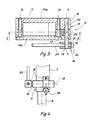
- a measurement support 1 comprises a bracket 2 with adjustable height and a setting 3 formed here by a circular plate whose upper face constitutes a reference surface 4 for the measurement.
- the bracket 2 supports a measuring probe 5 fitted with a lifting device 6 according to the invention which will now be described in detail with reference to FIGS. 2 to 4.
- the probe 5 may be that bearing the manufacturing reference MT 10P / 30P and placed on the market by the aforementioned company.
- this probe comprises a box r 7 in which is housed the transducer system (not shown) which, in the example described, is of the type with optical rule and with optoelectronic detector. From this housing projects a cylindrical end piece 8 integral with the housing and serving on the one hand for guiding a feeler rod 9 and on the other hand for fixing the feeler on the bracket 2.
- the feeler rod 9 is slidably mounted along its axis in the housing 7. At its free end, it carries a measuring member 10 which can take various forms such as those described in the brochure of the aforementioned Company.
- the feeler rod is resiliently biased outwards and it can be "raised” (that is to say partially retracted into the housing) to allow the measurement of a dimension, for example, the thickness of a piece P (figure 2).
- the housing 7 comprises a thread 11 in which, according to the known arrangements, comes screw the connection of a remote control device or of a pneumatic or electric lifting device (not shown).
- a remote control device or of a pneumatic or electric lifting device (not shown).
- Such a device comprises a sliding pusher 12 which is mechanically connected to the feeler rod so that when the pusher is retracted, the feeler rod also enters the housing 7. Since the connection mechanism is known per se, not give a detailed description here.
- the lifting device 6 is designed as follows.
- each part 13a or 13b of the lever has an extension 15, 16 respectively, the extension 16 of the part 13b being hollowed out to thus form with the extension 15 of the other part 13a a yoke 17 ( Figure 3).
- a lever 18 is mounted for rotation in the flange 13.
- This lever comprises a pin 19 rotatably mounted in holes 20 and 21 drilled respectively in the extensions 15 and 16 of the flange 13.
- This pin 19 defines an axis of rotation X - X of the lever 18, axis which, in this example, extends perpendicular to the large faces of the housing 7.
- the lever 18 further comprises two branches 22 and 23 each extending perpendicular to the axis X - X of the pin 19
- the first branch 22 cooperates at its free end with the sliding pusher 12, while the other branch 23 is produced in the form of a lever.
- the latter is made integral with the spindle 19 by means of a screw 24 which makes the angular orientation of the lever 23 adjustable relative to that of the branch 22.
- the elastic pushing device of the feeler has been symbolized by the spring 25.
- This device in addition to urging the feeler rod towards the outside, which is its main role, also tends to come out of the housing 7 the pusher 12, which the latter is prevented by a radial shoulder 12a.
- This shoulder abuts against the rear face of a nut 26 which is screwed into the internal thread 11 and through which the pusher 12 passes. The more the pusher 12 has returned to the housing, the more the feeler rod 9 also enters therein.
- FIG. 1 shows that the probe is connected to an amplification and analysis device 27 responsible for processing the electrical signal supplied by the transducer system (not shown) of the probe.
- the device 27 is connected to a display device 28.
- the measuring device When the measuring device is not in use, its feeler rod 9 can be completely extended, provided that the surface 4 of the setting 3 is sufficiently distant from the tip 10 of the rod.
- the bracket 2 fitted with the probe 5 is brought closer to the surface 4 of the fitting 3 so that the point 10 touches the latter and the apparatus 27 is adjusted so that the device d display indicates zero.
- the probing rod 9 is raised by actuating the handle 23 in the direction of the arrow F.
- the invention provides a simple and effective lifting device which can be actuated in the immediate vicinity of the probe and the part to be measured.
- the device according to the invention can be used with a measuring probe different from that mentioned above, but comprising a lifting system whose pusher is similar and mounted in the same way in the housing of the probe.
- the invention can be used in measurement equipment other than that specifically described.
- the lifting device according to the invention is easily removable, so that one can easily use the probe 5 with conventional lifting systems, if desired, after dismantling the lifting device according to the invention .
- the lever 18 can also be equipped with other actuation means than the handle 23, such as a knurled button, for example, screwed onto the pin 19 in place of the handle 23.
Landscapes
- Physics & Mathematics (AREA)
- General Physics & Mathematics (AREA)
- A Measuring Device Byusing Mechanical Method (AREA)
- Length Measuring Devices With Unspecified Measuring Means (AREA)
- Length-Measuring Instruments Using Mechanical Means (AREA)
Applications Claiming Priority (2)
| Application Number | Priority Date | Filing Date | Title |
|---|---|---|---|
| FR8612832 | 1986-09-11 | ||
| FR8612832A FR2603982A1 (fr) | 1986-09-11 | 1986-09-11 | Palpeur de mesure de dimensions |
Publications (1)
| Publication Number | Publication Date |
|---|---|
| EP0260583A1 true EP0260583A1 (de) | 1988-03-23 |
Family
ID=9338921
Family Applications (1)
| Application Number | Title | Priority Date | Filing Date |
|---|---|---|---|
| EP87113150A Withdrawn EP0260583A1 (de) | 1986-09-11 | 1987-09-09 | Taster zur Dimensionsmessung |
Country Status (4)
| Country | Link |
|---|---|
| US (1) | US4805310A (de) |
| EP (1) | EP0260583A1 (de) |
| JP (1) | JPS6370101A (de) |
| FR (1) | FR2603982A1 (de) |
Cited By (2)
| Publication number | Priority date | Publication date | Assignee | Title |
|---|---|---|---|---|
| EP0503245A1 (de) * | 1991-03-08 | 1992-09-16 | Dr.Ing.h.c. F. Porsche Aktiengesellschaft | Stationäre Einrichtung und Verfahren zur Verschleiss- und Dickenmessung an Bremsbelägen von Scheibenbremsen |
| CN109506544A (zh) * | 2018-12-25 | 2019-03-22 | 芜湖新宝超声波设备有限公司 | 一种用于汽车饰件的检测装置 |
Families Citing this family (8)
| Publication number | Priority date | Publication date | Assignee | Title |
|---|---|---|---|---|
| US5117561A (en) * | 1989-02-23 | 1992-06-02 | Greenslade Joe E | Rotatable gauging plate for a fastener dimension measuring machine |
| US5012592A (en) * | 1989-02-23 | 1991-05-07 | Greenslade Joe E | Fastener dimension measuring machine |
| JP2002257502A (ja) * | 2001-03-05 | 2002-09-11 | Junichi Kushibiki | 厚さ測定装置及び測定方法 |
| CN101236059A (zh) * | 2007-02-02 | 2008-08-06 | 深圳富泰宏精密工业有限公司 | 测量设备及其测量方法 |
| JP5021014B2 (ja) * | 2009-10-30 | 2012-09-05 | 日本碍子株式会社 | 積層体の形成方法 |
| CN102840844B (zh) * | 2011-06-20 | 2015-06-10 | 纬创资通股份有限公司 | 检测治具及利用检测治具的检测方法 |
| SE537530C2 (sv) * | 2013-04-26 | 2015-06-02 | Plockmatic Int Ab | Häftesframställningsmaskin med tjocklekssensor |
| JP7204274B1 (ja) * | 2022-10-04 | 2023-01-16 | 東将精工株式会社 | 測定器具補助具 |
Citations (3)
| Publication number | Priority date | Publication date | Assignee | Title |
|---|---|---|---|---|
| DE863419C (de) * | 1951-02-25 | 1953-01-19 | Siemens Ag | Universalmessgeraet fuer Dicken- und Formtoleranzen von Werkstuecken |
| GB1149602A (en) * | 1966-01-13 | 1969-04-23 | Burton H Marshall | Document counting apparatus |
| DE2754223A1 (de) * | 1977-12-06 | 1979-06-07 | Daimler Benz Ag | Vorrichtung zum messen der einbettwinkel von textil- und stahleinlagen in einem fahrzeugreifen |
Family Cites Families (3)
| Publication number | Priority date | Publication date | Assignee | Title |
|---|---|---|---|---|
| US1488818A (en) * | 1920-09-16 | 1924-04-01 | Johansson Ab C E | Indicating device for measuring instruments |
| US1671737A (en) * | 1922-02-21 | 1928-05-29 | James G Norton | Measuring apparatus |
| GB542231A (en) * | 1940-06-27 | 1941-12-31 | Sigma Instr Co Ltd | Improvements in or relating to linear-dimension gauges or comparators |
-
1986
- 1986-09-11 FR FR8612832A patent/FR2603982A1/fr not_active Withdrawn
-
1987
- 1987-09-04 US US07/093,362 patent/US4805310A/en not_active Expired - Fee Related
- 1987-09-09 EP EP87113150A patent/EP0260583A1/de not_active Withdrawn
- 1987-09-10 JP JP62225415A patent/JPS6370101A/ja active Pending
Patent Citations (3)
| Publication number | Priority date | Publication date | Assignee | Title |
|---|---|---|---|---|
| DE863419C (de) * | 1951-02-25 | 1953-01-19 | Siemens Ag | Universalmessgeraet fuer Dicken- und Formtoleranzen von Werkstuecken |
| GB1149602A (en) * | 1966-01-13 | 1969-04-23 | Burton H Marshall | Document counting apparatus |
| DE2754223A1 (de) * | 1977-12-06 | 1979-06-07 | Daimler Benz Ag | Vorrichtung zum messen der einbettwinkel von textil- und stahleinlagen in einem fahrzeugreifen |
Cited By (2)
| Publication number | Priority date | Publication date | Assignee | Title |
|---|---|---|---|---|
| EP0503245A1 (de) * | 1991-03-08 | 1992-09-16 | Dr.Ing.h.c. F. Porsche Aktiengesellschaft | Stationäre Einrichtung und Verfahren zur Verschleiss- und Dickenmessung an Bremsbelägen von Scheibenbremsen |
| CN109506544A (zh) * | 2018-12-25 | 2019-03-22 | 芜湖新宝超声波设备有限公司 | 一种用于汽车饰件的检测装置 |
Also Published As
| Publication number | Publication date |
|---|---|
| US4805310A (en) | 1989-02-21 |
| JPS6370101A (ja) | 1988-03-30 |
| FR2603982A1 (fr) | 1988-03-18 |
Similar Documents
| Publication | Publication Date | Title |
|---|---|---|
| EP2433085B1 (de) | Dreidimensionale messvorrichtung | |
| EP0634624B1 (de) | Gerät zum Messen einer Klemmkraft, die durch eine bewegbare Stange einer Längenmessvorrichtung ausgeübt wird | |
| FR2582974A1 (fr) | Dispositif pour effectuer un changement automatique d'outils de mesure dans un robot ou une machine de mesure | |
| EP2164685A1 (de) | Klemme für handhabungsroboter mit verbesserter greifgenauigkeit und mindestens eine solche klemme umfassender handhabungsroboter | |
| EP0260583A1 (de) | Taster zur Dimensionsmessung | |
| EP1577050A1 (de) | Werkzeugswechselvorrichtung | |
| EP0236371B1 (de) | Mikrometer mit numerischer darstellung | |
| EP0177744B1 (de) | Messkopf zur Diametermessung von zylindrischen Objekten | |
| EP1945405B1 (de) | Verfahren und vorrichtung zur einstellung der einpasstiefe eines werkzeugs in einem werkzeughalter | |
| EP1672309A1 (de) | Motorisierter und orientierbarer Messkopf | |
| EP0432557A1 (de) | Gerät zur Messung einer Abmessung eines Objekts | |
| EP0085605A1 (de) | Greifvorrichtung mit Greifkraftmesssystem, versehen mit einer mehrere Freiheitsgrade aufweisenden gegliederten Struktur eingebaut zwischen seiner Kontaktplatte und seinem Halter | |
| FR2534683A1 (fr) | Extensometre, notamment pour extensometrie a chaud | |
| EP0918264B9 (de) | Positionseinstellvorrichtung für eine auf einem Uhrwerkhemmungsanker montierte Palette | |
| FR2630032A1 (fr) | Appareil de montage pour anneaux de retenue | |
| EP0261500A1 (de) | Ausrüstung zur Dimensionsmessung von mechanischen Gegenständen | |
| EP0210892A1 (de) | Vielseitige Vorrichtung zum Eichen und Prüfer des Anziehmoments eines schrauben-mutterartigen Verbindungsgliedes | |
| CH634407A5 (fr) | Instrument de mesure de cotes. | |
| EP0677720A1 (de) | Vorrichtung zur Profilmessung einer ebenen Oberfläche | |
| FR2638229A1 (fr) | Verificateur d'arbre a mesure comparative | |
| EP0360693A1 (de) | Vorrichtung zur Messung der Festigkeit eines verformbaren Gegenstandes | |
| EP0855575A1 (de) | Messwertgebervorrichtung, insbesondere zum Ermitteln der räumlichen Lage eines Objekts, wie z.B. der Lage einer Fahrzeugwindschutzscheibe relativ zum Fahrzeug | |
| CH640936A5 (en) | Angular displacement sensor | |
| CH691879A5 (fr) | Appareil de mesure de longueurs. | |
| CH339742A (fr) | Pied à coulisse |
Legal Events
| Date | Code | Title | Description |
|---|---|---|---|
| PUAI | Public reference made under article 153(3) epc to a published international application that has entered the european phase |
Free format text: ORIGINAL CODE: 0009012 |
|
| AK | Designated contracting states |
Kind code of ref document: A1 Designated state(s): CH DE FR GB LI SE |
|
| 17P | Request for examination filed |
Effective date: 19880601 |
|
| 17Q | First examination report despatched |
Effective date: 19890828 |
|
| STAA | Information on the status of an ep patent application or granted ep patent |
Free format text: STATUS: THE APPLICATION IS DEEMED TO BE WITHDRAWN |
|
| 18D | Application deemed to be withdrawn |
Effective date: 19900109 |
|
| RIN1 | Information on inventor provided before grant (corrected) |
Inventor name: BEAUMANN, FERNAND |