EP0260583A1 - Feeler for measuring dimensions - Google Patents
Feeler for measuring dimensions Download PDFInfo
- Publication number
- EP0260583A1 EP0260583A1 EP87113150A EP87113150A EP0260583A1 EP 0260583 A1 EP0260583 A1 EP 0260583A1 EP 87113150 A EP87113150 A EP 87113150A EP 87113150 A EP87113150 A EP 87113150A EP 0260583 A1 EP0260583 A1 EP 0260583A1
- Authority
- EP
- European Patent Office
- Prior art keywords
- probe
- housing
- lever
- rod
- feeler
- Prior art date
- Legal status (The legal status is an assumption and is not a legal conclusion. Google has not performed a legal analysis and makes no representation as to the accuracy of the status listed.)
- Withdrawn
Links
Images


Classifications
-
- G—PHYSICS
- G01—MEASURING; TESTING
- G01B—MEASURING LENGTH, THICKNESS OR SIMILAR LINEAR DIMENSIONS; MEASURING ANGLES; MEASURING AREAS; MEASURING IRREGULARITIES OF SURFACES OR CONTOURS
- G01B5/00—Measuring arrangements characterised by the use of mechanical techniques
- G01B5/02—Measuring arrangements characterised by the use of mechanical techniques for measuring length, width or thickness
- G01B5/06—Measuring arrangements characterised by the use of mechanical techniques for measuring length, width or thickness for measuring thickness
- G01B5/061—Measuring arrangements characterised by the use of mechanical techniques for measuring length, width or thickness for measuring thickness height gauges
Definitions
- the present invention relates to dimension measuring instruments and relates more particularly to a measuring probe making it possible to supply a signal representing the dimension to be measured, this signal being exploited by applying it to a counter which is capable of display the measured dimension.
- Such a probe comprises a housing containing a transducer system, such as an optical rule for example, cooperating with an opto-electronic device capable of transforming the displacement of the rule into an electrical signal usable by the counter.
- a transducer system such as an optical rule for example
- the optical rule is coupled to a feeler rod slidably mounted in the housing and intended, at the time of the measurement, to come to be applied to the part to be measured, the latter being placed against a reference stop formed on the instrument of measurement.
- the feeler rod is associated with an elastic pushing device mounted in the housing and permanently urging the rod towards its extreme extended position.
- This pushing device can comprise a simple spring or possibly be produced in the form of a hydraulically or electrically controlled mechanism.
- the feeler rod must first be brought to its retracted position to allow the positioning of the part to be measured against the reference stop, then be released so that its tip can come into contact with the part.
- the feeler comprises means for lifting the feeler rod which are intended to move the latter towards its fully retracted position, against the action of the elastic thrust device.
- the lifting means comprise a flexible cable which makes it possible to control the lifting of the feeler rod in the manner of remote controls of cameras.
- the manufacturer of this probe also offers an automatic lifting device with pneumatic control which allows automation of the measurement process.
- Document GB 1 149 602 describes a device for counting the sheets of a stack of sheets comprising a measuring probe fitted with a probing rod mounted to slide in the housing of this probe between an extreme unstable retracted position and a stable position extended. This rod is permanently biased towards this extended position by an elastic return pushing device also mounted in the probe housing.
- the counting device also comprises a frame in which slides a support piece by means of which a stack of sheets can be clamped against a reference surface of the frame.
- the support piece can be raised by a mechanism comprising a lever arm to which a lever is coupled.
- the lever arm is also used to raise the direct probe rod which, however, does not come into direct contact with the stack of sheets during the measurement.
- the lever arm as well as the support piece serve to transmit to the probe rod the movement which it must perform between its extended position and that which corresponds to the height of the stack of sheets.
- This known device is unsuitable for carrying out measurements on mechanical parts, with the precision that the probe itself is capable of providing, since between the tip of the feeler rod and the surface of the part to be measured (the stack sheets) are interposed several movable members which introduce inevitable measurement errors whose magnitude is much greater than the tolerances with which a probe measuring dimensions of the kind of the present application must work.
- the object of the invention is to provide a measuring probe comprising a simple and direct manual lifting device, not interposing any part between the feeler rod and the part to be measured.
- the subject of the invention is therefore a measuring probe for a device for measuring dimensions, comprising a housing, a probing rod mounted to slide in the housing between an extreme unstable retracted position and a stable extended position towards which this rod is biased.
- an elastic return pushing device also mounted in the housing, and a rewashing device comprising a pivoting member which is mechanically coupled on the one hand to a manual actuating member also pivoting and on the other hand to said feeler rod to allow it to be brought into its retracted position against the return force of said elastic return device, characterized in that said pivoting member and said manual actuating member are mounted in common on a same pivot axis mounted in a support fixed to the probe housing, said pivoting member being directly coupled to said elastic return pushing device.
- the pivoting member does not act directly on the feeler rod, but on the elastic return pushing device of the probe so that it does not introduce any error in the measurement.
- the fact that the pivoting member and the actuating member are mounted on the same axis a great simplicity of construction is obtained.
- the support is mounted directly on the probe housing, the construction of the assembly is picked up and easily adapted on a measurement station placed in a prototype workshop for example.
- the support is formed by a flange enclosing the housing of the probe and arranged in an easily removable manner thereon.
- the probe can easily be adapted, sometimes to be used without the lifting device, sometimes with it.
- FIG. 1 represents a general view of a measuring equipment provided with a probe with which is associated a lifting device according to the invention.
- a measurement support 1 comprises a bracket 2 with adjustable height and a setting 3 formed here by a circular plate whose upper face constitutes a reference surface 4 for the measurement.
- the bracket 2 supports a measuring probe 5 fitted with a lifting device 6 according to the invention which will now be described in detail with reference to FIGS. 2 to 4.
- the probe 5 may be that bearing the manufacturing reference MT 10P / 30P and placed on the market by the aforementioned company.
- this probe comprises a box r 7 in which is housed the transducer system (not shown) which, in the example described, is of the type with optical rule and with optoelectronic detector. From this housing projects a cylindrical end piece 8 integral with the housing and serving on the one hand for guiding a feeler rod 9 and on the other hand for fixing the feeler on the bracket 2.
- the feeler rod 9 is slidably mounted along its axis in the housing 7. At its free end, it carries a measuring member 10 which can take various forms such as those described in the brochure of the aforementioned Company.
- the feeler rod is resiliently biased outwards and it can be "raised” (that is to say partially retracted into the housing) to allow the measurement of a dimension, for example, the thickness of a piece P (figure 2).
- the housing 7 comprises a thread 11 in which, according to the known arrangements, comes screw the connection of a remote control device or of a pneumatic or electric lifting device (not shown).
- a remote control device or of a pneumatic or electric lifting device (not shown).
- Such a device comprises a sliding pusher 12 which is mechanically connected to the feeler rod so that when the pusher is retracted, the feeler rod also enters the housing 7. Since the connection mechanism is known per se, not give a detailed description here.
- the lifting device 6 is designed as follows.
- each part 13a or 13b of the lever has an extension 15, 16 respectively, the extension 16 of the part 13b being hollowed out to thus form with the extension 15 of the other part 13a a yoke 17 ( Figure 3).
- a lever 18 is mounted for rotation in the flange 13.
- This lever comprises a pin 19 rotatably mounted in holes 20 and 21 drilled respectively in the extensions 15 and 16 of the flange 13.
- This pin 19 defines an axis of rotation X - X of the lever 18, axis which, in this example, extends perpendicular to the large faces of the housing 7.
- the lever 18 further comprises two branches 22 and 23 each extending perpendicular to the axis X - X of the pin 19
- the first branch 22 cooperates at its free end with the sliding pusher 12, while the other branch 23 is produced in the form of a lever.
- the latter is made integral with the spindle 19 by means of a screw 24 which makes the angular orientation of the lever 23 adjustable relative to that of the branch 22.
- the elastic pushing device of the feeler has been symbolized by the spring 25.
- This device in addition to urging the feeler rod towards the outside, which is its main role, also tends to come out of the housing 7 the pusher 12, which the latter is prevented by a radial shoulder 12a.
- This shoulder abuts against the rear face of a nut 26 which is screwed into the internal thread 11 and through which the pusher 12 passes. The more the pusher 12 has returned to the housing, the more the feeler rod 9 also enters therein.
- FIG. 1 shows that the probe is connected to an amplification and analysis device 27 responsible for processing the electrical signal supplied by the transducer system (not shown) of the probe.
- the device 27 is connected to a display device 28.
- the measuring device When the measuring device is not in use, its feeler rod 9 can be completely extended, provided that the surface 4 of the setting 3 is sufficiently distant from the tip 10 of the rod.
- the bracket 2 fitted with the probe 5 is brought closer to the surface 4 of the fitting 3 so that the point 10 touches the latter and the apparatus 27 is adjusted so that the device d display indicates zero.
- the probing rod 9 is raised by actuating the handle 23 in the direction of the arrow F.
- the invention provides a simple and effective lifting device which can be actuated in the immediate vicinity of the probe and the part to be measured.
- the device according to the invention can be used with a measuring probe different from that mentioned above, but comprising a lifting system whose pusher is similar and mounted in the same way in the housing of the probe.
- the invention can be used in measurement equipment other than that specifically described.
- the lifting device according to the invention is easily removable, so that one can easily use the probe 5 with conventional lifting systems, if desired, after dismantling the lifting device according to the invention .
- the lever 18 can also be equipped with other actuation means than the handle 23, such as a knurled button, for example, screwed onto the pin 19 in place of the handle 23.
Landscapes
- Physics & Mathematics (AREA)
- General Physics & Mathematics (AREA)
- A Measuring Device Byusing Mechanical Method (AREA)
- Length Measuring Devices With Unspecified Measuring Means (AREA)
- Length-Measuring Instruments Using Mechanical Means (AREA)
Abstract
Le palpeur (5) fait partie d'un équipement de mesure (1, 27, 28) pour permettre la mesure de dimensions de pièces placées sur un posage (3). La tige de palpage (9) du palpeur peut être relev ée à l'aide d'un levier (18) pivotant dans une bride (13) montée de façon amovible sur le boîtier (7) du palpeur. Le dispositif de relevage (6) équipé de ce levier est maniable et permet une mesure rapide de pièces.The probe (5) is part of a measuring equipment (1, 27, 28) to allow the measurement of dimensions of parts placed on a setting (3). The feeler rod (9) of the probe can be raised using a lever (18) pivoting in a flange (13) removably mounted on the housing (7) of the probe. The lifting device (6) equipped with this lever is handy and allows rapid measurement of parts.
Description
La présente invention concerne les instruments de mesure de dimensions et elle a trait, plus particulièrement, à un palpeur de mesure permettant de fournir un signal représentant la dimension à mesurer, ce signal étant exploité en l'appliquant à un compteur qui est capable d'afficher la dimension mesurée.The present invention relates to dimension measuring instruments and relates more particularly to a measuring probe making it possible to supply a signal representing the dimension to be measured, this signal being exploited by applying it to a counter which is capable of display the measured dimension.
Un tel palpeur comporte un boîtier contenant un système transducteur, tel qu'une règle optique par exemple, coopérant avec un dispositif opto-électronique capable de transformer le déplacement de la règle en un signal électrique exploitable par le compteur.Such a probe comprises a housing containing a transducer system, such as an optical rule for example, cooperating with an opto-electronic device capable of transforming the displacement of the rule into an electrical signal usable by the counter.
La règle optique est couplée à une tige de palpage montée coulissante dans le boîtier et destinée, au moment de la mesure, à venir s'appliquer sur la pièce à mesurer, celle-ci étant posée contre une butée de référence ménagée sur l'instrument de mesure.The optical rule is coupled to a feeler rod slidably mounted in the housing and intended, at the time of the measurement, to come to be applied to the part to be measured, the latter being placed against a reference stop formed on the instrument of measurement.
La tige de palpage est associée à une dispositif de poussée élastique monté dans le boîtier et sollicitant en permanence la tige vers sa position extrême sortie. Ce dispositif de poussée peut comprendre un simple ressort ou éventuellement être réalisé sous la forme d'un mécanisme à commande hydraulique ou électrique. Quoi qu'il en soit, pour effectuer la mesure, la tige de palpage doit d'abord être amenée vers sa position rentrée pour permettre la mise en place de la pièce à mesurer contre la butée de référence, puis être relâchée pour que sa pointe de mesure puisse venir en contact avec la pièce. C'est pourquoi, le palpeur comporte des moyens de relevage de la tige de palpage qui sont destinés à déplacer celle-ci vers sa position entièrement rentrée, à l'encontre de l'action du dispositif de poussée élastique.The feeler rod is associated with an elastic pushing device mounted in the housing and permanently urging the rod towards its extreme extended position. This pushing device can comprise a simple spring or possibly be produced in the form of a hydraulically or electrically controlled mechanism. Anyway, to perform the measurement, the feeler rod must first be brought to its retracted position to allow the positioning of the part to be measured against the reference stop, then be released so that its tip can come into contact with the part. This is why, the feeler comprises means for lifting the feeler rod which are intended to move the latter towards its fully retracted position, against the action of the elastic thrust device.
Un palpeur du type que l'on vient de décrire brièvement est disponible sur le marché et on en trouve une description complète dans une brochure de la Société Dr. Johannes Heidenhain, Postfach 1260, D-8225 Traunreut, Allemagne Fédérale.A probe of the type just described is available on the market and a complete description can be found in a brochure from the Company Dr. Johannes Heidenhain, Postfach 1260, D-8225 Traunreut, Federal Germany.
Dans ce cas, les moyens de relevage comportent un câble flexible qui permet de commander le relevage de la tige de palpage à la façon des commandes à distance des appareils photographiques. Le constructeur de ce palpeur propose également un dispositif de relevage automatique à commande pneumatique qui autorise une automatisation du processus de mesure.In this case, the lifting means comprise a flexible cable which makes it possible to control the lifting of the feeler rod in the manner of remote controls of cameras. The The manufacturer of this probe also offers an automatic lifting device with pneumatic control which allows automation of the measurement process.
Les inconvénients de ces deux dispositifs de relevage consiste en ce qu'ils sont peut compatibles avec des mesures rapides manuelles comme on désire fréquemment en faire dans des ateliers de prototype par exemple, ou pour contrôler des petites séries de pièces.The disadvantages of these two lifting devices is that they are compatible with rapid manual measurements as is frequently desired in prototype workshops for example, or to control small series of parts.
Dans le document GB 1 149 602, on décrit un dispositif de comptage des feuilles d'un empilement de feuilles comportant un palpeur de mesure muni d'une tige de palpage montée coulissante dans le boîtier de ce palpeur entre une position extrême instable rétractée et une position stable sortie. Cette tige est sollicitée en permanence vers cette position sortie par un dispositif de poussée à rappel élastique également monté dans le boîtier du palpeur.
Le dispositif de comptage comprend également un châssis dans lequel coulisse une pièce d'appui au moyen de laquelle un empilement de feuilles peut être serré contre une surface de référence du châssis. La pièce d'appui peut être relevée par un mécanisme comportant un bras de levier auquel est couplé une manette. Le bras de levier sert également à relever par contact direct la tige du palpeur qui, elle, ne vient pas directement en contact avec l'empilement de feuilles lors de la mesure. En d'autres termes, le bras de levier ainsi que la pièce d'appui servent à transmettre à la tige du palpeur le mouvement qu'elle doit effectuer entre sa position sortie et celle qui correspond à la hauteur de l'empilement de feuilles. Ce dispositif connu est inapproprié pour effectuer des mesures sur des pièces mécaniques, avec la précision que le palpeur lui-même est capable de f ournir, car entre la pointe de la tige de palpage et la surface de la pièce à mesurer (l'empilement de feuilles) sont interposées plusieurs organes mobiles qui introduisent des erreurs de mesure inévitables dont l'ampleur est bien plus grande que les tolérances avec lesquelles un palpeur de mesure de dimensions du genre de la présente demande doit travailler.The counting device also comprises a frame in which slides a support piece by means of which a stack of sheets can be clamped against a reference surface of the frame. The support piece can be raised by a mechanism comprising a lever arm to which a lever is coupled. The lever arm is also used to raise the direct probe rod which, however, does not come into direct contact with the stack of sheets during the measurement. In other words, the lever arm as well as the support piece serve to transmit to the probe rod the movement which it must perform between its extended position and that which corresponds to the height of the stack of sheets. This known device is unsuitable for carrying out measurements on mechanical parts, with the precision that the probe itself is capable of providing, since between the tip of the feeler rod and the surface of the part to be measured (the stack sheets) are interposed several movable members which introduce inevitable measurement errors whose magnitude is much greater than the tolerances with which a probe measuring dimensions of the kind of the present application must work.
On doit aussi remarquer que ce mécanisme rend le dispositif complexe et par conséquent coûteux.It should also be noted that this mechanism makes the device complex and therefore expensive.
L'invention a pour but de fournir un palpeur de mesure comportant un dispositif de relevage manuel simple et direct, n'interposant aucune pièce entre la tige de palpage et la pièce à mesurer.The object of the invention is to provide a measuring probe comprising a simple and direct manual lifting device, not interposing any part between the feeler rod and the part to be measured.
L'invention a donc pour objet un palpeur de mesure pour un équipement de mesure de dimensions, comportant un boîtier, une tige de palpage montée coulissante dans le boîtier entre une position extrême instable rétractée et une position stable sortie vers laquelle cette tige est sollicitée en permanence par un dispositif de poussée à rappel élastique, également monté dans le boîtier, et un dispositif de relavage comprenant un organe pivotant qui est couplé mécaniquement d'une part à une organe d'actionnement manuel également pivotant et d'autre part, à ladite tige de palpage pour permettre d'amener celle-ci vers sa position rétractée à l'encontre de la force de rappel dudit dispositif de rappel élastique, caractérisé en ce que ledit organe pivotant et ledit organe d'actionnement manuel sont montés en commun sur un même axe de pivotement monté dans un support fixé sur le boîtier du palpeur, ledit organe pivotant étant couplé directement audit dispositif de poussée à rappel élastique.The subject of the invention is therefore a measuring probe for a device for measuring dimensions, comprising a housing, a probing rod mounted to slide in the housing between an extreme unstable retracted position and a stable extended position towards which this rod is biased. permanently by an elastic return pushing device, also mounted in the housing, and a rewashing device comprising a pivoting member which is mechanically coupled on the one hand to a manual actuating member also pivoting and on the other hand to said feeler rod to allow it to be brought into its retracted position against the return force of said elastic return device, characterized in that said pivoting member and said manual actuating member are mounted in common on a same pivot axis mounted in a support fixed to the probe housing, said pivoting member being directly coupled to said elastic return pushing device.
Grâce à ces caractéristiques, l'organe pivotant n'agit pas directement sur la tige de palpage, mais sur le dispositif de poussée à rappel élastique du palpeur de sorte qu'il n'introduit aucune erreur dans la mesure. En outre, du fait que l'organe pivotant et l'organe d'actionnement sont montés sur un même axe, on obtient une grande simplicité de construction. Enfin, du fait que le support est monté directement sur le boîtier du palpeur, la construction de l'ensemble est ramassée et s'adapte facilement sur un poste de mesure placé dans un atelier de prototypes par exemple.Thanks to these characteristics, the pivoting member does not act directly on the feeler rod, but on the elastic return pushing device of the probe so that it does not introduce any error in the measurement. In addition, the fact that the pivoting member and the actuating member are mounted on the same axis, a great simplicity of construction is obtained. Finally, because the support is mounted directly on the probe housing, the construction of the assembly is picked up and easily adapted on a measurement station placed in a prototype workshop for example.
Suivant une caractéristique particulièrement avantageuse de l'invention, le support est formé par une bride enserrant le boîtier du palpeur et agencé de façon facilement amovible sur celui-ci.According to a particularly advantageous characteristic of the invention, the support is formed by a flange enclosing the housing of the probe and arranged in an easily removable manner thereon.
De cette manière, le palpeur peut facilement être adapté, tantôt pour être utilisé sans le dispositif de relevage, tantôt avec celui-ci.In this way, the probe can easily be adapted, sometimes to be used without the lifting device, sometimes with it.
L'invention sera mieux comprise à l'aide de la description qui va suivre d'un mode de réalisation de l'invention, cette description n'étant donnée qu'à titre d'exemple et faite en référence aux dessins annexés sur lesquels:
- - la figure 1 est une vue en perspective d'un équipement de mesure comportant un palpeur suivant l'invention;
- - la figure 2 est une vue en coupe partielle, à plus grande échelle, du palpeur suivant l'invention;
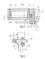
- - la figure 3 est une vue en coupe suivant la ligne III - III de la figure 2;
- - la figure 4 est une vue latérale partielle du palpeur et de son dispositif releveur.
- - Figure 1 is a perspective view of a measuring equipment comprising a probe according to the invention;
- - Figure 2 is a partial sectional view, on a larger scale, of the probe according to the invention;
- - Figure 3 is a sectional view along line III - III of Figure 2;
- - Figure 4 is a partial side view of the probe and its lifting device.
La figure 1 représente une vue générale d'un équipement de mesure pourvu d'un palpeur auquel est associé un dispositif de relevage suivant l'invention. Un support de mesure 1 comporte une potence 2 à hauteur réglable et un posage 3 formé ici par un plateau circulaire dont la face supérieure constitue une surface de référence 4 pour la mesure.FIG. 1 represents a general view of a measuring equipment provided with a probe with which is associated a lifting device according to the invention. A
La potence 2 supporte un palpeur de mesure 5 équipé d'un dispositif de relevage 6 suivant l'invention que l'on va maintenant décrire en détail en se référant aux figures 2 à 4.The bracket 2 supports a
Le palpeur 5 peut être celui portant la référence de fabrication MT 10P/30P et mis sur le marché par la Société précitée.The
De façon connue, ce palpeur comporte un boîtie r 7 dans lequel est logé le système transducteur (non représenté) qui, dans l'exemple décrit, est du type à règle optique et à détecteur optoélectronique. De ce boîtier fait saillie un embout cylindrique 8 solidaire du boîtier et servant d'une part au guidage d'une tige de palpage 9 et d'autre part à la fixation du palpeur sur la potence 2.In known manner, this probe comprises a
La tige de palpage 9 est montée coulissante selon son axe dans le boîtier 7. A son extrémité libre, elle porte un organe de mesure 10 qui peut revêtir des formes diverses telles que celles décrites dans la brochure de la Société précitée. La tige de palpage est sollicitée élastiquement vers l'extérieur et elle peut être "relevée" (c'est-à-dire rentrée partiellement dans le boîtier) pour permettre la mesure d'une dimension, par exemple, l'épaisseur d'une pièce P (figure 2).The
A cet effet, et toujours de façon connue, le boîtier 7 comporte un taraudage 11 dans lequel, selon les agencements connus, vient se visser le raccord d'un dispositif de commande à distance ou d'un dispositif pneumatique ou électrique de relevage (non représenté). Un tel dispositif comporte un poussoir coulissant 12 qui est connecté mécaniquement à la tige de palpage de telle sorte que lorsque le poussoir est rentré, la tige de palpage rentre également dans le boîtier 7. Le mécanisme de connexion étant connu en soi, on n'en donne pas une description détaillée ici.To this end, and still in a known manner, the
Suivant l'invention le dispositif de relevage 6 est conçu de la façon suivante.According to the invention the
Une bride 13, faite en deux parties en forme de U 13a et 13b fixées l'une à l'autre par des vis 14, enserre le boîtier 7 du palpeur 5.A
D'un côté de cette bride 13, c'est-à-dire près de l'une des petites faces du boîtier 7, chaque partie 13a ou 13b du levier comporte un prolongement 15, 16 respectivement, le prolongement 16 de la partie 13b étant évidé pour former ainsi avec le prolongement 15 de l'autre partie 13a une chape 17 (figure 3).On one side of this
Un levier 18 est monté à rotation dans la bride 13. Ce levier comporte une broche 19 montée à rotation dans des trous 20 et 21 percés respectivement dans les prolongements 15 et 16 de la bride 13. Cette broche 19 définit un axe de rotation X - X du levier 18, axe qui, dans cet exemple, s'étend perpendiculairement aux grandes faces du boîtier 7. Le levier 18 comporte en outre deux branches 22 et 23 s'étendant chacune perpendiculairement à l'axe X - X de la broche 19. La première branche 22 coopère par son extrémité libre avec le poussoir coulissant 12, tandis que l'autre branche 23 est réalisée sous la forme d'une manette. Celle-ci est rendue solidaire de la broche 19 au moyen d'une vis 24 qui rend l'orientation angulaire de la manette 23 réglable par rapport à celle de la branche 22.A
Sur la figure 2, on a symbolisé le dispositif de poussée élastique du palpeur par le ressort 25. Ce dispositif, en plus de solliciter la tige de palpage vers l'extérieur, ce qui est son rôle principal, tend également à sortir du boîtier 7 le poussoir 12, ce dont ce dernier est empêché grâce à un épaulement radial 12a. Cet épaulement vient en butée contre la face arrière d'un écrou 26 qui est vissé dans le taraudage 11 et dans lequel passe le poussoir 12. Plus le poussoir 12 est rentré dans le boîtier, plus la tige de palpage 9 rentre également dans celui-ci.In FIG. 2, the elastic pushing device of the feeler has been symbolized by the
La figure 1 montre que le palpeur est connecté à un appareil d'amplification et d'analyse 27 chargé de traiter le signal électrique fourni par le système transducteur (non représenté) du palpeur. L'appareil 27 est connecté à un dispositif d'affichage 28.FIG. 1 shows that the probe is connected to an amplification and
Lorsque l'appareil de mesure n'est pas utilisé, sa tige de palpage 9 peut être complètement sortie, à condition que la surface 4 du posage 3 soit éloignée suffisamment de la pointe 10 de la tige. Pour donner une référence à une mesure à effectuer, on rapproche la potence 2 équipée du palpeur 5 de la surface 4 du posage 3 de manière que la pointe 10 touche celle-ci et on règle l'appareil 27 de telle manière que l e dispositif d'affichage indique zéro.When the measuring device is not in use, its
Puis pour mesurer l'épaisseur de la pièce P, on relève la tige de palpage 9 en actionnant la manette 23 dans le sens de la flèche F.Then to measure the thickness of the part P, the
La pièce P étant mise sur le posage 3, la manette est doucement ramenée vers l'arrière jusqu'à ce que la pointe 10 de la tige de palpage 9 repose sur la pièce P. Une nouvelle lecture sur le dispositif d'affichage en donne alors l'épaisseur. Le levier 18 occupe alors la position représentée en traits pleins sur la figure 2.The part P being placed on the
Pour enlever la pièce P, il suffit de ramener la manette 23 vers la position haute représentée sur la figure 2, moyennant quoi la tige de palpage 9 est complètement rentrée pour occuper sa position instable rentrée. Le levier 18 étant de nouveau relâché, la tige 9 sort complètement de l'appareil et une nouvelle mesure peut être effectuée.To remove the part P, it suffices to return the
On constate donc que l'invention fournit un dipositif de relevage simple et efficace pouvant être actionné dans le voisinage immédiat du palpeur et de la pièce à mesurer.It can therefore be seen that the invention provides a simple and effective lifting device which can be actuated in the immediate vicinity of the probe and the part to be measured.
Bien entendu, de nombreuses variantes de l'invention peuvent être imaginée par les spécialistes.Of course, many variants of the invention can be imagined by specialists.
En particulier, le dispositif suivant l'invention peut être utilisé avec un palpeur de mesure différent de celui mentionné ci-dessus, mais comprenant un système de relevage dont le poussoir est analogue et monté de la même façon dans le boîtier du palpeur. De plus, l'invention peut être utilisée dans un équipement de mesure autre que celui spécifiquement décrit.In particular, the device according to the invention can be used with a measuring probe different from that mentioned above, but comprising a lifting system whose pusher is similar and mounted in the same way in the housing of the probe. In addition, the invention can be used in measurement equipment other than that specifically described.
On notera aussi que les dispositif de relevage suivant l'invention est facilement démontable, de sorte que l'on peut aisément utiliser le palpeur 5 avec les systèmes classiques de relevage, si cela est souhaité, après démontage du dispositif de relevage suivant l'invention.Note also that the lifting device according to the invention is easily removable, so that one can easily use the
Le levier 18 peut également être équipé d'un autre moyen d'actionnement que la manette 23, tel qu'un bouton moleté, par exemple, vissé sur la broche 19 à la place de la manette 23.The
Claims (5)
Applications Claiming Priority (2)
| Application Number | Priority Date | Filing Date | Title |
|---|---|---|---|
| FR8612832 | 1986-09-11 | ||
| FR8612832A FR2603982A1 (en) | 1986-09-11 | 1986-09-11 | DIMENSIONAL MEASURING PROBE |
Publications (1)
| Publication Number | Publication Date |
|---|---|
| EP0260583A1 true EP0260583A1 (en) | 1988-03-23 |
Family
ID=9338921
Family Applications (1)
| Application Number | Title | Priority Date | Filing Date |
|---|---|---|---|
| EP87113150A Withdrawn EP0260583A1 (en) | 1986-09-11 | 1987-09-09 | Feeler for measuring dimensions |
Country Status (4)
| Country | Link |
|---|---|
| US (1) | US4805310A (en) |
| EP (1) | EP0260583A1 (en) |
| JP (1) | JPS6370101A (en) |
| FR (1) | FR2603982A1 (en) |
Cited By (2)
| Publication number | Priority date | Publication date | Assignee | Title |
|---|---|---|---|---|
| EP0503245A1 (en) * | 1991-03-08 | 1992-09-16 | Dr.Ing.h.c. F. Porsche Aktiengesellschaft | Stationary device and procedure for measuring wear and thickness at brake pads of disc brakes |
| CN109506544A (en) * | 2018-12-25 | 2019-03-22 | 芜湖新宝超声波设备有限公司 | A kind of detection device for automobile decoration piece |
Families Citing this family (9)
| Publication number | Priority date | Publication date | Assignee | Title |
|---|---|---|---|---|
| US5117561A (en) * | 1989-02-23 | 1992-06-02 | Greenslade Joe E | Rotatable gauging plate for a fastener dimension measuring machine |
| US5012592A (en) * | 1989-02-23 | 1991-05-07 | Greenslade Joe E | Fastener dimension measuring machine |
| JP2002257502A (en) | 2001-03-05 | 2002-09-11 | Junichi Kushibiki | Device and method for measuring thickness |
| CN101236059A (en) * | 2007-02-02 | 2008-08-06 | 深圳富泰宏精密工业有限公司 | Measurement equipment and its measurement method |
| JP5021014B2 (en) * | 2009-10-30 | 2012-09-05 | 日本碍子株式会社 | Method for forming laminate |
| CN102840844B (en) * | 2011-06-20 | 2015-06-10 | 纬创资通股份有限公司 | Detection jig and detection method using detection jig |
| SE537530C2 (en) * | 2013-04-26 | 2015-06-02 | Plockmatic Int Ab | Booklet making machine with thickness sensor |
| CN111077373A (en) * | 2020-01-20 | 2020-04-28 | 麦峤里(上海)半导体科技有限责任公司 | Conductive film multi-probe measuring device and measuring method thereof |
| JP7204274B1 (en) * | 2022-10-04 | 2023-01-16 | 東将精工株式会社 | Measuring instrument aid |
Citations (3)
| Publication number | Priority date | Publication date | Assignee | Title |
|---|---|---|---|---|
| DE863419C (en) * | 1951-02-25 | 1953-01-19 | Siemens Ag | Universal measuring device for thickness and shape tolerances of workpieces |
| GB1149602A (en) * | 1966-01-13 | 1969-04-23 | Burton H Marshall | Document counting apparatus |
| DE2754223A1 (en) * | 1977-12-06 | 1979-06-07 | Daimler Benz Ag | Measurement of tyre insert embedded angle - uses transparent discs on swivelling frame and automatically prints out angle between directions |
Family Cites Families (3)
| Publication number | Priority date | Publication date | Assignee | Title |
|---|---|---|---|---|
| US1488818A (en) * | 1920-09-16 | 1924-04-01 | Johansson Ab C E | Indicating device for measuring instruments |
| US1671737A (en) * | 1922-02-21 | 1928-05-29 | James G Norton | Measuring apparatus |
| GB542231A (en) * | 1940-06-27 | 1941-12-31 | Sigma Instr Co Ltd | Improvements in or relating to linear-dimension gauges or comparators |
-
1986
- 1986-09-11 FR FR8612832A patent/FR2603982A1/en not_active Withdrawn
-
1987
- 1987-09-04 US US07/093,362 patent/US4805310A/en not_active Expired - Fee Related
- 1987-09-09 EP EP87113150A patent/EP0260583A1/en not_active Withdrawn
- 1987-09-10 JP JP62225415A patent/JPS6370101A/en active Pending
Patent Citations (3)
| Publication number | Priority date | Publication date | Assignee | Title |
|---|---|---|---|---|
| DE863419C (en) * | 1951-02-25 | 1953-01-19 | Siemens Ag | Universal measuring device for thickness and shape tolerances of workpieces |
| GB1149602A (en) * | 1966-01-13 | 1969-04-23 | Burton H Marshall | Document counting apparatus |
| DE2754223A1 (en) * | 1977-12-06 | 1979-06-07 | Daimler Benz Ag | Measurement of tyre insert embedded angle - uses transparent discs on swivelling frame and automatically prints out angle between directions |
Cited By (2)
| Publication number | Priority date | Publication date | Assignee | Title |
|---|---|---|---|---|
| EP0503245A1 (en) * | 1991-03-08 | 1992-09-16 | Dr.Ing.h.c. F. Porsche Aktiengesellschaft | Stationary device and procedure for measuring wear and thickness at brake pads of disc brakes |
| CN109506544A (en) * | 2018-12-25 | 2019-03-22 | 芜湖新宝超声波设备有限公司 | A kind of detection device for automobile decoration piece |
Also Published As
| Publication number | Publication date |
|---|---|
| US4805310A (en) | 1989-02-21 |
| FR2603982A1 (en) | 1988-03-18 |
| JPS6370101A (en) | 1988-03-30 |
Similar Documents
| Publication | Publication Date | Title |
|---|---|---|
| EP2433085B1 (en) | Three-dimensional measurement device | |
| EP0634624B1 (en) | Device for measuring a clamping force applied by a movable rod of a length measuring device | |
| EP0260583A1 (en) | Feeler for measuring dimensions | |
| FR2582974A1 (en) | DEVICE FOR PERFORMING AN AUTOMATIC CHANGE OF MEASURING TOOLS IN A ROBOT OR MEASURING MACHINE | |
| EP2164685A1 (en) | Clamp for manipulating robot with enhanced gripping accuracy and manipulating robot comprising at least one such clamp | |
| EP1577050A1 (en) | Tool change apparatus | |
| EP0236371B1 (en) | Digital display micrometer | |
| EP0177744B1 (en) | Measuring head to measure diameters of cylindric objects | |
| EP1945405B1 (en) | Method and device for adjusting the fitting depth of a tool in a tool-holder | |
| EP1672309A1 (en) | Motorised and orientable measuring head | |
| EP0432557A1 (en) | Instrument for measuring a dimension of an object | |
| FR2534683A1 (en) | Extensometer, especially for hot extensometry. | |
| EP0918264B9 (en) | Device for adjusting the position of a pallet-stone mounted in clockwork escapement pallets | |
| EP0261500A1 (en) | Equipment for measuring the dimensions of mechanical parts | |
| CH634407A5 (en) | DIMENSION MEASURING INSTRUMENT. | |
| EP0677720A1 (en) | Device for performing profile measurement of a plane surface | |
| FR2638229A1 (en) | Device with comparative measurement for checking a shaft | |
| FR2574588A1 (en) | "Joystick" | |
| EP0855575A1 (en) | Sensing device in particular for determining the relative position of an object in space, such as the position of a windshield of a vehicle with respect to this vehicle | |
| CH640936A5 (en) | Angular displacement sensor | |
| CH691879A5 (en) | Length measuring tool , in which the measuring force or pressure can be precisely adjusted and which is linked to the displacement of a measuring sensor by a predetermined function | |
| CH339742A (en) | Caliper | |
| FR2684440A1 (en) | Apparatus for measuring angular separations | |
| FR2788848A1 (en) | Tolerance checking of components using a simple test element that pivots during checking on contact with the test component, with the pivot angle linked to a proximity sensor with a yes no output or linked to a controller unit | |
| CH464565A (en) | Staple calibrator |
Legal Events
| Date | Code | Title | Description |
|---|---|---|---|
| PUAI | Public reference made under article 153(3) epc to a published international application that has entered the european phase |
Free format text: ORIGINAL CODE: 0009012 |
|
| AK | Designated contracting states |
Kind code of ref document: A1 Designated state(s): CH DE FR GB LI SE |
|
| 17P | Request for examination filed |
Effective date: 19880601 |
|
| 17Q | First examination report despatched |
Effective date: 19890828 |
|
| STAA | Information on the status of an ep patent application or granted ep patent |
Free format text: STATUS: THE APPLICATION IS DEEMED TO BE WITHDRAWN |
|
| 18D | Application deemed to be withdrawn |
Effective date: 19900109 |
|
| RIN1 | Information on inventor provided before grant (corrected) |
Inventor name: BEAUMANN, FERNAND |