EP0270858B1 - Outlet nozzle for an inlet valve of a whirlpool bath - Google Patents
Outlet nozzle for an inlet valve of a whirlpool bath Download PDFInfo
- Publication number
- EP0270858B1 EP0270858B1 EP87116544A EP87116544A EP0270858B1 EP 0270858 B1 EP0270858 B1 EP 0270858B1 EP 87116544 A EP87116544 A EP 87116544A EP 87116544 A EP87116544 A EP 87116544A EP 0270858 B1 EP0270858 B1 EP 0270858B1
- Authority
- EP
- European Patent Office
- Prior art keywords
- outlet
- piston
- channel
- nozzle according
- outlet nozzle
- Prior art date
- Legal status (The legal status is an assumption and is not a legal conclusion. Google has not performed a legal analysis and makes no representation as to the accuracy of the status listed.)
- Expired - Lifetime
Links
- XLYOFNOQVPJJNP-UHFFFAOYSA-N water Substances O XLYOFNOQVPJJNP-UHFFFAOYSA-N 0.000 claims abstract description 68
- 238000007789 sealing Methods 0.000 claims description 16
- 239000000872 buffer Substances 0.000 claims description 8
- 239000000463 material Substances 0.000 claims description 4
- 230000015572 biosynthetic process Effects 0.000 claims description 2
- 239000011248 coating agent Substances 0.000 claims description 2
- 238000000576 coating method Methods 0.000 claims description 2
- 230000000903 blocking effect Effects 0.000 claims 1
- 238000000034 method Methods 0.000 claims 1
- 230000007704 transition Effects 0.000 claims 1
- 238000009826 distribution Methods 0.000 abstract description 21
- 230000000694 effects Effects 0.000 abstract description 10
- 238000004140 cleaning Methods 0.000 description 9
- 239000000203 mixture Substances 0.000 description 9
- 239000007788 liquid Substances 0.000 description 8
- 238000011001 backwashing Methods 0.000 description 3
- 238000010276 construction Methods 0.000 description 3
- 239000011324 bead Substances 0.000 description 2
- 239000000356 contaminant Substances 0.000 description 2
- 230000001105 regulatory effect Effects 0.000 description 2
- 238000003287 bathing Methods 0.000 description 1
- 230000037396 body weight Effects 0.000 description 1
- 238000011109 contamination Methods 0.000 description 1
- 230000008021 deposition Effects 0.000 description 1
- 239000012530 fluid Substances 0.000 description 1
- 230000009760 functional impairment Effects 0.000 description 1
- 230000001771 impaired effect Effects 0.000 description 1
- 239000012535 impurity Substances 0.000 description 1
- 238000009434 installation Methods 0.000 description 1
- 210000003127 knee Anatomy 0.000 description 1
- 238000004519 manufacturing process Methods 0.000 description 1
- 239000002245 particle Substances 0.000 description 1
- 210000003903 pelvic floor Anatomy 0.000 description 1
- 238000011144 upstream manufacturing Methods 0.000 description 1
Images
Classifications
-
- A—HUMAN NECESSITIES
- A61—MEDICAL OR VETERINARY SCIENCE; HYGIENE
- A61H—PHYSICAL THERAPY APPARATUS, e.g. DEVICES FOR LOCATING OR STIMULATING REFLEX POINTS IN THE BODY; ARTIFICIAL RESPIRATION; MASSAGE; BATHING DEVICES FOR SPECIAL THERAPEUTIC OR HYGIENIC PURPOSES OR SPECIFIC PARTS OF THE BODY
- A61H33/00—Bathing devices for special therapeutic or hygienic purposes
- A61H33/60—Components specifically designed for the therapeutic baths of groups A61H33/00
- A61H33/601—Inlet to the bath
- A61H33/6021—Nozzles
- A61H33/6057—Comprising means producing pulsating or intermittent streams
-
- A—HUMAN NECESSITIES
- A61—MEDICAL OR VETERINARY SCIENCE; HYGIENE
- A61H—PHYSICAL THERAPY APPARATUS, e.g. DEVICES FOR LOCATING OR STIMULATING REFLEX POINTS IN THE BODY; ARTIFICIAL RESPIRATION; MASSAGE; BATHING DEVICES FOR SPECIAL THERAPEUTIC OR HYGIENIC PURPOSES OR SPECIFIC PARTS OF THE BODY
- A61H33/00—Bathing devices for special therapeutic or hygienic purposes
- A61H33/02—Bathing devices for use with gas-containing liquid, or liquid in which gas is led or generated, e.g. carbon dioxide baths
- A61H33/027—Gas-water mixing nozzles therefor
-
- A—HUMAN NECESSITIES
- A61—MEDICAL OR VETERINARY SCIENCE; HYGIENE
- A61H—PHYSICAL THERAPY APPARATUS, e.g. DEVICES FOR LOCATING OR STIMULATING REFLEX POINTS IN THE BODY; ARTIFICIAL RESPIRATION; MASSAGE; BATHING DEVICES FOR SPECIAL THERAPEUTIC OR HYGIENIC PURPOSES OR SPECIFIC PARTS OF THE BODY
- A61H33/00—Bathing devices for special therapeutic or hygienic purposes
- A61H33/60—Components specifically designed for the therapeutic baths of groups A61H33/00
- A61H33/601—Inlet to the bath
- A61H33/6021—Nozzles
- A61H33/6063—Specifically adapted for fitting in bathtub walls
Definitions
- the invention relates to an outlet nozzle for the outlet valve of a whirlpool tub with a water supply channel and an air supply channel, in which the water flow is mixed with the air flow due to the action of an injector.
- a nozzle combination with an axially movable jet deflection plate which can achieve sealing on its circumferential line with respect to a nozzle housing.
- a water supply line opens into the nozzle housing below the jet deflection plate, while air can be supplied to the lower opening of the nozzle housing.
- the beam deflection plate has a cylindrical approach, in which irradiation openings are kept clear. When the water supply line or the opening is pressurized, the jet deflecting plate can lift axially upwards from its lower sealing position up to a stop, as a result of which water and air can escape together from the jet openings into the tub interior.
- the disadvantage here is that the position of the jet deflector can be influenced from the outside, in particular the jet deflector is pressed into the closed position under the body weight of the tub user, which due to the geometric conditions the injector effect is only relatively small and that the jet deflector is only returned to its sealing position due to its own weight reached.
- a nozzle for an air bubbler of a water basin is proposed, which is supplied through a channel with water.
- a check valve is provided at the nozzle outlet, which is opened by pump pressure and closes automatically, preferably by spring force or moved by the bath water flowing back in, as soon as the pump pressure is switched off.
- the flow rate can also be regulated by means of the check valve by opening more or less cross-section.
- the check valve acts as a baffle plate and widens the escaping water jet, which improves the mixing of air and water and reduces the size of the air bubbles.
- DE-U-8 606 463 (FIG. 10) also proposes a nozzle combination in which the extension of an air supply nozzle projects into the air-guiding channel. Coaxial to the air supply nozzle, a support flange is inserted into the basin wall, which carries an axially adjustable ring with a conical inner bore, which together with the air supply nozzle forms an annular channel, the free cross section of which can be changed by adjusting the ring. Dirty bath water can penetrate into the nozzle combination and deposit there.
- DE-U-8 606 463 (FIG.
- nozzle combination in which a water-air mixture is fed via a check valve to an axially fixed baffle plate through which the water-air mixture passes axially and under which the water-air mixture can exit into the interior of the pool through an outlet opening parallel to the pool floor.
- dirty bath water can accumulate inside the nozzle housing.
- a device must be connected upstream, with which the water-air mixture is first produced.
- a nozzle combination for the supply of compressed air is also proposed, in which in a carrier flange which in the The basin wall or the pelvic floor is clamped, a cover valve is seated, which in the idle state runs almost at the same level as the installation level, is lifted out of its seat when pressure is present and releases the outlet path for the compressed air. When the air pressure drops, the cover valve is returned to its valve seat. This can be done by the water column in the inner pool or by its own weight or by spring force.
- a check valve can be provided in the supply line.
- the compressed air can exit axially or essentially radially into the inner basin. Through the axial outlet opening, contaminated bath water can penetrate into the nozzle housing and settle there even when the nozzle combination is closed. An injector effect is not intended, a special device would be required for this. Another disadvantage is that the opening position can be affected by the pool user.
- a nozzle combination is known from EP-A-0 209 646 (FIG. 10), which belongs to the state of the art only according to ⁇ 54 (3) EPC, but which essentially corresponds to the nozzle combination of FIG. 10 of DE-U-8 606 463 additionally has an independent check valve in the outlet channel of a steering jet nozzle.
- the check valve is already loaded with a water-air mixture so that there is no longer any injector effect.
- the air supply nozzle is also provided with an outer ring-shaped stop, which means that if a ring is adjusted, the volume can be regulated until the air supply is completely shut off.
- the ring used to adjust the volume can also be equipped as an independent check valve or the restoring force of the returning bath water can be used. This creates a relatively complex construction and the additional disadvantage that on the one hand on the check valve formed by the adjustable ring the compressed air and on the other hand the water pressure acts, which creates undefined conditions.
- the object of the invention is to design an outlet nozzle of the type mentioned at the outset such that a high hydro-pneumatic massage effect can be achieved if the outlet nozzle is prevented from being contaminated by impurities present in the water of the whirlpool.
- an outlet nozzle for the outlet valve of a whirlpool tub with a water supply channel and an air supply channel in which the water flow is mixed with the air flow due to the action of an injector, in that the water supply channel merges into a radially outwardly leading annular outlet channel , which is formed in a plate-shaped distribution body and the valve body of the outlet valve, that the preferably annular air supply duct opens into an annular space between the plate-shaped distribution body and the valve body or the valve housing or the tub wall which adjoins the outlet duct radially outwards, and that with the inner surface of the distribution body, the outlet channel and / or the surfaces forming the intermediate space of at least one concentrically surrounding the water supply channel Precise piston movable relative to the valve body are formed, which in its closed position closes the outlet channel and / or the space adjoining the outlet channel in a liquid and / or gas-tight manner.
- the contaminants in the water of the whirlpool such as hair, dirt particles or the like, cannot settle in the outlet nozzle and thus lead to a functional impairment or even blockage of the outlet nozzle.
- the piston While in the open position of the piston or pistons Piston surfaces with the inner surface of the distribution body form the outlet channel and the space adjoining it radially outwards, the piston moves or the pistons move with their surfaces essentially axially toward the inner surface of the distribution body when the outlet nozzle is switched off, so that at least one opposite Areas of these surfaces ensure a liquid-tight seal of the water supply duct and / or the air supply duct.
- the at least one piston is expediently guided in the valve body or on the valve housing or on the tub wall for the axial stroke movement.
- the air supply duct has individual air supply ducts which are in flow connection with bores which extend axially in the piston.
- the bores of the air supply duct can merge into an annular duct opening into the intermediate space.
- the bores arranged in the piston or the annular duct of the air supply duct open or open into the intermediate space immediately behind an outlet slot formed in the edge region of the outlet duct.
- the surfaces of the distribution body and the piston that come into contact with one another in the closed position of the piston but at least the areas of the surfaces of the piston that come into contact with the inner surface of the distribution body as sealing surfaces, optionally with a flexible surface Coating or a pad or insert made of rubber or the like.
- the surfaces of the piston which extend to the bores or the annular channel of the air supply channel or which extend on both sides of the outlet slot of the outlet channel are arranged such that they are offset with respect to one another in such a way that they correspond to the inner surface of the distribution body Surface delimiting the space jumps back relative to the surface delimiting the outlet channel, and that the piston wall adjoining the surface delimiting the outlet channel has a recess in the region of the outlet slot or the air supply channel, via which a sealing strip of flexible material connected to the piston surface is flexible in the open position of the piston Material, possibly with the formation of the outlet slot, extends in a substantially tangential direction to the piston surface, which is pressed into the recess in the closed position of the piston.
- This advantageous embodiment according to the invention makes it possible to provide only a reciprocating piston with bores for the air supply and at the same time to keep the height of the intermediate space larger than the width of the outlet slot for a uniform flow of the water-air mixture and low noise.
- the recess in the piston wall is provided with an axial depth which is approximately the result of the piston surface assigned to the intermediate space and over itself Air supply channel or the bores in the piston tangential inwardly extending line is specified.
- the front section of the sealing strip which projects beyond the expansion and in the open position of the piston with the inner surface of the distribution body forms the outlet slot, is pressed into the recess in the closed position, the resulting bead of the flexible sealing strip being pressed against the inner surface of the distribution body.
- the piston can be moved from the closed position into the open position against the force of a spring energy store by the force or pressure of the water flowing out of the water supply channel.
- the spring force accumulator is advantageously formed by springs, rubber buffers or the like, which are arranged in an annular space that essentially concentrically surrounds the water supply channel between the piston and a bearing surface of the valve body.
- the annular space provided in the valve body has a wall area extending axially upward from the support surface for receiving the piston mounted on the spring force accumulator, that an inner wall area arranged concentrically to the water supply channel of the piston forms an annular gap with the wall region of the valve body facing it, and that the annular space opens into a return channel which extends axially downward in the valve body and which is possibly connected to the outflow of the whirlpool tub via a shut-off device.
- cleaning of the outlet nozzle according to the invention is advantageously achieved by injecting a cleaning liquid through the water supply channel into the outlet nozzle, and thus an outlet channel which is sealed against the ingress of water and possibly against a supplied air, and which is injected via the water supply channel into the Valve body provided annular space flows and from there through a return channel into the drain of the jacuzzi.
- the pressure of the cleaning liquid emerging from the outlet openings of the water supply channel is to be determined such that the piston or pistons remain or remain in their closed position. This achieves an effective backwashing or cleaning of the outlet nozzle according to the invention.
- ring-shaped rubber buffers concentrically surrounding the water supply channel are provided on both sides of the air supply channel, which at least in the closed position of the piston keep an area of the annular space free and thereby separate them from one another in two liquid and / or gas-tight manner Divide sections with the radially outer section communicating with the air supply duct.
- the annular gap expediently has approximately half of the Width of the outlet slot corresponding width of 0.1 to 1 mm, preferably 0.6 mm, so that in the open position of the piston even in the absence of a shut-off element between the return channel and the outflow of the whirlpool, only a small amount of the water introduced into the water supply channel during operation the outlet nozzle is lost.
- the distribution body can be held, for example, by a bayonet, screw, suction, plug-in or magnetic connection on the valve body, which may have an axial extension, or be formed integrally therewith. Further advantageous features of the outlet nozzle according to the invention emerge from claims 14 to 20. These serve essentially a simple construction with high effectiveness of the emerging massage jet.
- the outlet nozzle according to the invention can in particular also be operated with a pulsating water supply and / or air supply.
- the single figure schematically illustrates in section an embodiment of an outlet nozzle according to the invention with a closing mechanism and a backwash system.
- the outlet nozzle shown in the drawing for the outlet valve 34 of a whirlpool has a valve body 39 with a centrally arranged water supply channel 35, which is provided with outlet openings 56 opening radially into an outlet channel 36.
- the outlet channel 36 is through the inner surface 41 of an extension 67 provided with an engagement groove 68 of the Valve body 39 attachable plate-shaped distribution body 37 and formed by a surface 44 of a piston 49.
- the height of the outlet channel 36 is reduced from the radially inside to the radially outside by the surface 44 of the piston 49 tapering obliquely towards the tub wall 42 from the radially inside to the radially outside and the inner surface 41 of the distribution body 37 from a radially inner one, approximately parallel to the tub wall 42 extending section merges into an obliquely inclined area, whereby an outlet slot 45 is formed on the radially outer circumference of the outlet channel 36.
- This outlet channel 36 which tapers radially from the inside to the outside, gives the water emerging from the outlet openings 56 the speed required to exert a suction effect on the outlet behind the outlet slot 45 directly behind the outlet slot 45 via an axially extending upward in the valve body 39 if necessary, exercise air introduced into the air supply duct 38, which has individual air supply ducts 53.
- the mixing of the water with the sucked-in air takes place in a space 46 adjoining the outlet channel 36 radially outwards.
- This space 46 is formed by the outer edge region of the inner surface 41 of the distribution body 37 and the surface 48 of the piston 49.
- the intermediate space 46 which is designed as an annular channel, extends away from the tub wall 42 at a slight angle.
- the intermediate space 46 has an approximately constant width which exceeds the width of the outlet slot 45 by a factor of 2 in the exemplary embodiment chosen here.
- the piston 49 which has the surfaces 44 and 48, is received in an annular space 61 of the valve body 39 with an axial wall region concentrically surrounding the water supply channel 35 63 and a radially outwardly extending bearing surface 62.
- spring force accumulators 60 are provided in the form of rubber buffers on which the piston 49 is supported with its underside and which oppose one another support the bearing surface 62 of the annular space 61.
- the two annular spring force accumulators 60 concentrically surrounding the water supply channel 35 are arranged on both sides of the bores 54 of the air supply channel 38 which extend axially upwards and merge into an annular channel 47.
- the rubber buffer 60 is formed between the piston 44 and the support surfaces 62 of the valve body 49, an intermediate space of the annular space 61 which is divided by the spring force accumulators 60 designed as a rubber buffer into two sections 50, 51 which are separated from one another in a liquid-tight and / or gas-tight manner, the radially outer section 51 for the passage of air communicates with the bores 54 of the piston 49 and the section of the air supply duct 38 coming from below.
- the restoring force of the spring force accumulator 60 is to be selected so that during operation of the outlet valve 34 by the pressure of the water emerging via the outlet openings 56 and, supported by the pressure of the water-air mixture formed in the intermediate space 46, the pistons 49 with their surfaces 44 and 48 axially downward is pressed into the open position. If, on the other hand, the outlet valve 34 is slatted off, the restoring force of the spring-core accumulator 60 brings about an axial stroke of the piston 49, the end region of its surface 44 and its surface 48 being pressed against the inner surface 41 of the distribution body 37 and thus the outlet valve 34 against inflow of bathing water seal from the whirlpool tub.
- the sections of the surfaces 44 and 48 that come into contact with the inner surface 41 of the distribution body 37 in the closed position of the piston 49 are provided with a sealing strip 59.
- the piston 49 has a recess 58 immediately below the outlet slot 45 and in the piston wall 57 delimiting the annular gap 47 for the supply of air, which in the open position of the adjacent sealing strip 59 is protruded to form the underside of the outlet slot 45.
- the sealing strip 59 is pressed into the recess 58, the resulting bead of the sealing strip 59 on the knee of the recess 58 being pressed firmly against the inner surface 41 of the distribution body 37 and sealing the interior of the outlet channel 36 in a liquid-tight manner.
- the radially inner annular spring force accumulator 60 serves as a seal for the radially inner section 50 of the annular space by means of the spring force accumulator 60, the clearance of the annular space 61 with respect to the radially outwardly extending further section 51 for the air supply, so that water or cleaning fluid cannot penetrate into the air supply system.
- the pressure of the rinsing liquid entering via the water supply channel 36 and entering the outlet channel 36 via the outlet openings 56 is to be set so that the piston 49 remains in its closed position.
- the outlet nozzle With the invented outlet nozzle, a new kind of massage feeling is created by an intensive water-air mixture due to the excellent injector effect, which flows out essentially parallel to the tub wall and from which fine air bubbles rise in the tub water to massage the tub user.
- the outlet nozzle according to the invention enables an automatic, reliable sealing of its interior from the bath water of the whirlpool, which would otherwise lead to contamination of the supply system and germ deposition in the latter, when the operating system is shut down.
- the supply system can be backwashed by backwashing with water or a cleaning liquid in an advantageous manner when the plant is at a standstill, without the cleaning liquid getting into the whirlpool bath.
Abstract
Description
Die Erfindung betrifft eine Austrittsdüse für das Austrittsventil einer Whirlpool-Wanne mit einem Wasserzufuhrkanal und einem Luftzufuhrkanal, bei welcher der Wasserstrom mit dem Luftstrom aufgrund von Injektorwirkung miteinander gemischt werden.The invention relates to an outlet nozzle for the outlet valve of a whirlpool tub with a water supply channel and an air supply channel, in which the water flow is mixed with the air flow due to the action of an injector.
Aus der DE-A 3 630 806 ist eine Düsenkombination mit einer axial beweglichen Strahlablenkplatte bekannt, welche an ihrer Umfangslinie gegenüber einem Düsengehäuse Abdichtung erreichen kann. Unterhalb der Strahlablenkplatte mündet eine Wasserzufuhrleitung in das Düsengehäuse, während der unteren Öffnung des Düsengehäuses Luft zugeführt werden kann. Die Strahlablenkplatte hat einen zylindrischen Ansatz, in welchem Einstrahlöffnungen freigehalten sind. Unter Druckbeauflagung der Wasserzufuhrleitung bzw. der Öffnung kann sich die Strahlablenkplatte aus ihrer unteren Abdichtlage axial bis zu einem Anschlag nach oben anheben, wodurch Wasser und Luft gemeinsam aus den Einstrahlöffnungen in das Wanneninnere austreten können. Nachteilig hierbei ist, daß die Stellung der Strahlablenkplatte von außen beeinflußbar ist, insbesondere die Strahlablenkplatte unter dem Körpergewicht des Wannenbenutzers in Schließstellung gedrückt wird, das aufgrund der geometrischen Verhältnisse die Injektorwirkung nur verhältnismäßig gering ist und daß die Strahlablenkplatte lediglich aufgrund ihres Eigengewichts wieder in ihre Abdichtstellung gelangt.From DE-A 3 630 806 a nozzle combination with an axially movable jet deflection plate is known, which can achieve sealing on its circumferential line with respect to a nozzle housing. A water supply line opens into the nozzle housing below the jet deflection plate, while air can be supplied to the lower opening of the nozzle housing. The beam deflection plate has a cylindrical approach, in which irradiation openings are kept clear. When the water supply line or the opening is pressurized, the jet deflecting plate can lift axially upwards from its lower sealing position up to a stop, as a result of which water and air can escape together from the jet openings into the tub interior. The disadvantage here is that the position of the jet deflector can be influenced from the outside, in particular the jet deflector is pressed into the closed position under the body weight of the tub user, which due to the geometric conditions the injector effect is only relatively small and that the jet deflector is only returned to its sealing position due to its own weight reached.
In der DE-U-8 606 463 (Figur 8), welche auf einen Eintragungstag vom 30.10.1986 und einen Bekanntmachungstag vom 11.12.1986 zurückgeht, ist eine Düse für eine Luftsprudelvorrichtung eines Wasserbeckens vorgeschlagen, welcher durch einen Kanal Wasser zugeführt wird. Am Düsenausgang ist ein Rückschlagventil vorgesehen, welches durch Pumpendruck geöffnet wird und selbsttätig, vorzugsweise durch Federkraft oder bewegt durch das zurückflutende Badewasser, schließt, sobald der Pumpendruck abgeschaltet wird. Auch die Durchflußmenge kann mittels des Rückschlagventils reguliert werden, indem mehr oder weniger Querschnitt freigegeben wird. Das Rückschlagventil wirkt als Prallscheibe und verbreitert den austretenden Wasserstrahl, wodurch eine Vermischung von Luft und Wasser verbessert werden und eine Verkleinerung der Luftblasen erfolgen soll. Auch hier ist die Öffnungsstellung des Rückschlagventils von außen beeinträchtigbar und die Injektorwirkung verhältnismäßig gering. In der DE-U-8 606 463 (Figur 10) ist ferner eine Düsenkombination vorgeschlagen, bei welcher in den luftführenden Kanal die Verlängerung einer Luftzufuhrdüse hineinragt. Koaxial zu der Luftzufuhrdüse ist in die Beckenwandung ein Trägerflansch eingesetzt, der einen axial verstellbaren Ring mit konischer Innenbohrung trägt, welcher zusammen mit der Luftzufuhrdüse einen Ringkanal bildet, dessen freier Querschnitt sich durch Verstellen des Ringes verändern läßt. Hierbei kann schmutziges Badewasser in die Düsenkombination eindringen und sich dort ablagern. In der DE-U-8 606 463 (Figur 18) ist ferner eine Düsenkombination vorgeschlagen, bei welcher ein Wasser-Luft-Gemisch über ein Rückschlagventil einer axial feststehenden Ablenkplatte zugeführt wird, durch welche das Wasser-Luft-Gemisch axial hindurchtreten und unter welcher das Wasser-Luft-Gemisch durch eine Austrittsöffnung parallel zum Beckenboden in das Beckeninnere austreten kann. Auch hier kann sich verschmutztes Badewasser im Inneren des Düsengehäuses ansammeln. Außerdem muß eine Vorrichtung vorgeschaltet sein, mit Hilfe welcher erst das Wasser-Luft-Gemisch hergestellt wird. In der DE-U-8 606 463 (Figur 19) ist auch eine Düsenkombination für die Zufuhr von Druckluft vorgeschlagen, bei welcher in einem Trägerflansch, welcher in die Beckenwand bzw. den Beckenboden eingespannt ist, ein Deckelventil sitzt, welches im Ruhezustand nahezu höhengleich mit der Einbauebene verläuft, bei anstehendem Druck aus seinem Sitz abgehoben wird und den Austrittsweg für die Druckluft freigibt. Das Deckelventil wird bei nachlassendem Luftdruck in seinen Ventilsitz zurückgestellt. Dies kann durch die anstehende Wassersäule im Innenbecken erfolgen oder durch Eigengewicht oder durch Federkraft. Zusätzlich kann ein Rückschlagventil in der Zufuhrleitung vorgesehen sein. Die Druckluft kann hierbei axial oder im wesentlichen radial in das Innenbecken austreten. Durch die axiale Austrittsöffnung kann auch im verschlossenen Zustand der Düsenkombination verschmutztes Badewasser in das Düsengehäuse eindringen und sich dort absetzen. Eine Injektorwirkung ist nicht vorgesehen, dazu bedürfte es einer besonderen Vorrichtung. Nachteilig ist hierbei ebenfalls, daß die Öffnungsstellung durch den Beckenbenutzer beeinträchtigt werden kann.In DE-U-8 606 463 (Figure 8), which refers to a day of registration dated October 30, 1986 and an announcement date dated December 11, 1986, a nozzle for an air bubbler of a water basin is proposed, which is supplied through a channel with water. A check valve is provided at the nozzle outlet, which is opened by pump pressure and closes automatically, preferably by spring force or moved by the bath water flowing back in, as soon as the pump pressure is switched off. The flow rate can also be regulated by means of the check valve by opening more or less cross-section. The check valve acts as a baffle plate and widens the escaping water jet, which improves the mixing of air and water and reduces the size of the air bubbles. Here too, the opening position of the check valve can be impaired from the outside and the injector effect is relatively low. DE-U-8 606 463 (FIG. 10) also proposes a nozzle combination in which the extension of an air supply nozzle projects into the air-guiding channel. Coaxial to the air supply nozzle, a support flange is inserted into the basin wall, which carries an axially adjustable ring with a conical inner bore, which together with the air supply nozzle forms an annular channel, the free cross section of which can be changed by adjusting the ring. Dirty bath water can penetrate into the nozzle combination and deposit there. DE-U-8 606 463 (FIG. 18) also proposes a nozzle combination in which a water-air mixture is fed via a check valve to an axially fixed baffle plate through which the water-air mixture passes axially and under which the water-air mixture can exit into the interior of the pool through an outlet opening parallel to the pool floor. Here too, dirty bath water can accumulate inside the nozzle housing. In addition, a device must be connected upstream, with which the water-air mixture is first produced. In DE-U-8 606 463 (Figure 19) a nozzle combination for the supply of compressed air is also proposed, in which in a carrier flange which in the The basin wall or the pelvic floor is clamped, a cover valve is seated, which in the idle state runs almost at the same level as the installation level, is lifted out of its seat when pressure is present and releases the outlet path for the compressed air. When the air pressure drops, the cover valve is returned to its valve seat. This can be done by the water column in the inner pool or by its own weight or by spring force. In addition, a check valve can be provided in the supply line. The compressed air can exit axially or essentially radially into the inner basin. Through the axial outlet opening, contaminated bath water can penetrate into the nozzle housing and settle there even when the nozzle combination is closed. An injector effect is not intended, a special device would be required for this. Another disadvantage is that the opening position can be affected by the pool user.
Aus der nur nach § 54 (3) EPÜ zum Stande der Technik gehörenden EP-A-0 209 646 (Figur 10) ist eine Düsenkombination bekannt, welche im wesentlichen der Düsenkombination von Figur 10 der DE-U-8 606 463 entspricht, jedoch zusätzlich in dem Austrittskanal einer Lenkstrahldüse ein selbständiges Rückschlagventil aufweist. Das Rückschlagventil wird bereits mit einem Wasser-Luft-Gemisch beauflagt, so daß dort keine Injektorwirkung mehr auftritt. Die Luftzufuhrdüse ist zusätzlich mit einem äußeren ringförmigen Anschlag versehen, wodurch bei Verstellen eines Ringes die Mengenregulierung bis zum vollständigen Absperren der Zufuhr der Luft erfolgen kann. Auch der der Mengenverstellung dienende Ring kann als selbständiges Rückschlagventil ausgestattet sein oder die Rückstellkraft des zurückströmenden Badewassers benutzt werden. Hierdurch entsteht eine verhältnismäßig aufwendige Konstruktion und der zusätzliche Nachteil, daß auf das von dem verstellbaren Ring gebildete Rückschlagventil einerseits die Druckluft und andererseits der Wasserdruck einwirkt, wodurch undefinierte Verhältnisse entstehen.A nozzle combination is known from EP-A-0 209 646 (FIG. 10), which belongs to the state of the art only according to § 54 (3) EPC, but which essentially corresponds to the nozzle combination of FIG. 10 of DE-U-8 606 463 additionally has an independent check valve in the outlet channel of a steering jet nozzle. The check valve is already loaded with a water-air mixture so that there is no longer any injector effect. The air supply nozzle is also provided with an outer ring-shaped stop, which means that if a ring is adjusted, the volume can be regulated until the air supply is completely shut off. The ring used to adjust the volume can also be equipped as an independent check valve or the restoring force of the returning bath water can be used. This creates a relatively complex construction and the additional disadvantage that on the one hand on the check valve formed by the adjustable ring the compressed air and on the other hand the water pressure acts, which creates undefined conditions.
Aufgabe der Erfindung ist es eine Austrittsdüse der eingangs genannten Art dahingehend auszubilden, daß bei Vermeidung einer Verschmutzung der Austrittsdüse durch im Wasser des Whirlpools vorhandene Verunreinigungen ein hoher hydro-pneumatischer Massageeffekt erzielbar ist.The object of the invention is to design an outlet nozzle of the type mentioned at the outset such that a high hydro-pneumatic massage effect can be achieved if the outlet nozzle is prevented from being contaminated by impurities present in the water of the whirlpool.
Diese Aufgabe wird erfindungsgemäß bei einer Austrittsdüse für das Austrittsventil einer Whirlpool-Wanne mit einem Wasserzufuhrkanal und einem Luftzufuhrkanal, bei welcher der Wasserstrom mit dem Luftstrom aufgrund von Injektorwirkung miteinander gemischt werden, dadurch gelöst, daß der Wasserzufuhrkanal in einen radial nach außen führenden kreisringförmigen Austrittskanal übergeht, welcher einem tellerförmigen Verteilungskörper und dem Ventilkörper des Austrittsventils gebildet ist, daß der vorzugsweise kreisringförmig ausgebildete Luftzufuhrkanal in einen sich radial nach außen an den Austrittskanal anschließenden kreisringförmigen Zwischenraum zwischen dem tellerförmigen Verteilungskörper und dem Ventilkörper bzw. dem Ventilgehäuse oder der Wannenwandung mündet, und daß die mit der Innenfläche des Verteilungskörpers den Austrittskanal und/oder den Zwischenraum bildenden Oberflächen von wenigstens einem den Wasserzufuhrkanal im wesentlichen konzentrisch umgebenden, relativ zu dem Ventilkörper beweglichen Kolben gebildet sind, welcher in seiner Schließstellung den Austrittskanal und/oder den sich an den Austrittskanal anschließenden Zwischenraum flüssigkeits- und/oder gasdicht abschließt.This object is achieved in an outlet nozzle for the outlet valve of a whirlpool tub with a water supply channel and an air supply channel, in which the water flow is mixed with the air flow due to the action of an injector, in that the water supply channel merges into a radially outwardly leading annular outlet channel , which is formed in a plate-shaped distribution body and the valve body of the outlet valve, that the preferably annular air supply duct opens into an annular space between the plate-shaped distribution body and the valve body or the valve housing or the tub wall which adjoins the outlet duct radially outwards, and that with the inner surface of the distribution body, the outlet channel and / or the surfaces forming the intermediate space of at least one concentrically surrounding the water supply channel Precise piston movable relative to the valve body are formed, which in its closed position closes the outlet channel and / or the space adjoining the outlet channel in a liquid and / or gas-tight manner.
Hierdurch können die sich im Wasser des Whirlpools befindlichen Verunreinigungen wie Haare, Schmutzpartikel oder dgl. nicht in der Austrittsdüse absetzen und damit zu einer Funktionsbeeinträchtigung oder gar einem Verstopfen der Austrittsdüse führen. Während in Öffnungsstellung des Kolbens bzw. der Kolben die Kolbenoberflächen mit der Innenfläche des Verteilungskörpers den Austrittskanal und den sich daran radial nach außen anschließenden Zwischenraum bilden, bewegt sich der Kolben bzw. bewegen sich die Kolben bei Abschalten der Austrittsdüse mit ihren Oberflächen im wesentlichen axial auf die Innenfläche des Verteilungskörpers zu, so daß zumindest gegenüberliegendem Bereiche dieser Flächen für einen flüssigkeitsdichten Abschluß des Wasserzufuhrkanals und/oder des Luftzufuhrkanals sorgen.As a result, the contaminants in the water of the whirlpool, such as hair, dirt particles or the like, cannot settle in the outlet nozzle and thus lead to a functional impairment or even blockage of the outlet nozzle. While in the open position of the piston or pistons Piston surfaces with the inner surface of the distribution body form the outlet channel and the space adjoining it radially outwards, the piston moves or the pistons move with their surfaces essentially axially toward the inner surface of the distribution body when the outlet nozzle is switched off, so that at least one opposite Areas of these surfaces ensure a liquid-tight seal of the water supply duct and / or the air supply duct.
Zweckmäßigerweise ist dabei für die axiale Hubbewegung der wenigstens einer Kolben im Ventilköper bzw. am Ventilgehäuse oder an der Wannenwandung geführt.The at least one piston is expediently guided in the valve body or on the valve housing or on the tub wall for the axial stroke movement.
Von Vorteil kann es auch sein, wenn der Luftzufuhrkanal Einzelluftzufuhrkanäle aufweist, welche mit in dem Kolben sich axial erstreckenden Bohrungen in Strömungsverbindung stehen.It can also be advantageous if the air supply duct has individual air supply ducts which are in flow connection with bores which extend axially in the piston.
Für eine gleichmäßige Einleitung der Luft in den Zwischenraum können nach einem weiterbildenden Vorschlag der Erfindung die Bohrungen des Luftzufuhrkanals in einen in den Zwischenraum mündenden Ringkanal übergehen.For a uniform introduction of the air into the intermediate space, the bores of the air supply duct can merge into an annular duct opening into the intermediate space.
Vorteilhaft hinsichtlich eines Sogeffektes für die zugeführte Luft ist es ferner, wenn die im Kolben angeordneten Bohrungen bzw. der Ringkanal des Luftzufuhrkanals unmittelbar hinter einem im Randbereich des Austrittskanals gebildeten Austrittsschlitz in den Zwischenraum münden bzw. mündet.With regard to a suction effect for the supplied air, it is also advantageous if the bores arranged in the piston or the annular duct of the air supply duct open or open into the intermediate space immediately behind an outlet slot formed in the edge region of the outlet duct.
Auch kann nach der Erfindung vorgesehen sein, daß die in Schließstellung des Kolbens zur Anlage miteinander kommenden Flächen des Verteilungskörpers und des Kolbens, mindestens aber die in Anlage mit der Innenfläche des Verteilungskörpers kommenden Bereiche der Oberflächen des Kolbens als Dichtflächen, ggf. mit einer flexiblen Beschichtung oder einer Auf- bzw. Einlage aus Gummi oder dgl. ausgebildet sind. Hierdurch wird neben einer guten Abdichtung des Inneren des Austrittsventils gegenüber einem mit Verunreinigungen beladenen Wasser gleichzeitig die mechanische Beanspruchung der in Schließstellung des Kolbens in Anlage miteinander kommenden Flächen vermindert, so daß eine hohe Lebensdauer des Austrittsventils erreicht wird.It can also be provided according to the invention that the surfaces of the distribution body and the piston that come into contact with one another in the closed position of the piston, but at least the areas of the surfaces of the piston that come into contact with the inner surface of the distribution body as sealing surfaces, optionally with a flexible surface Coating or a pad or insert made of rubber or the like. As a result, in addition to a good seal of the interior of the outlet valve against water laden with contaminants, the mechanical stress on the surfaces which come into contact with one another in the closed position of the piston is simultaneously reduced, so that a long service life of the outlet valve is achieved.
In Weiterbildung dieses Gedankens kann auch vorgesehen sein, daß in Öffnungsstellung des Kolbens die an die Bohrungen oder den Ringkanal des Luftzufuhrkanals reichenden bzw. sich beidseitig des Austrittsschlitzes des Austrittskanals erstreckenden Oberflächen des Kolbens derart gegeneinander versetzt angeordnet sind, daß die mit der Innenfläche des Verteilungskörpers den Zwischenraum begrenzende Oberfläche gegenüber der den Austrittskanal begrenzenden Oberfläche zurückspringt, und daß die sich an die den Austrittskanal begrenzende Oberfläche anschließende Kolbenwandung im Bereich des Austrittsschlitzes bzw. des Luftzufuhrkanals eine Ausnehmung aufweist, über welche sich in Öffnungsstellung des Kolbens eine mit der Kolbenoberfläche verbundene Dichtleiste aus flexibelm Material, ggf. unter Bildung des Austrittsschlitzes, mit im wesentlichen tangentialer Richtung zur Kolbenoberfläche erstreckt, welche in Schließstellung des Kolbens in die Ausnehmung eingedrückt ist. Diese vorteilhafte Ausgestaltung nach der Erfindung gestattet es, lediglich einen Hubkolben mit Bohrungen für die Luftzufuhr vorzusehen und gleichzeitig für eine gleichmäßige Strömung des Wasser-Luft-Gemisches sowie eine geringe Geräuschentwicklung die Höhe des Zwischenraumes größer als die Breite des Austrittsschlitzes zu halten. Um gleichzeitig eine Abdichtung des Austrittskanals durch den Hub eines Kolbens zu ermöglichen, ist die Ausnehmung in der Kolbenwandung vorgesehen mit einer axialen Tiefe, welche etwa durch die von der den Zwischenraum zugeordneten Kolbenoberfläche und sich über den Luftzufuhrkanal bzw. die Bohrungen im Kolben tangential nach innen erstreckende gedachte Linie vorgegeben ist. Dabei wird der vordere, die Ausdehnung überragende und in Öffnungsstellung des Kolbens mit der Innenfläche des Verteilungskörpers den Austrittsschlitz bildende Abschnitt der Dichtleiste in Schließstellung in die Ausnehmung hineingedrückt, wobei der dabei sich ergebende Wulst der flexiblen Dichtleiste an die Innenfläche des Verteilungskörpers angepreßt ist.In a further development of this idea, it can also be provided that, in the open position of the piston, the surfaces of the piston which extend to the bores or the annular channel of the air supply channel or which extend on both sides of the outlet slot of the outlet channel are arranged such that they are offset with respect to one another in such a way that they correspond to the inner surface of the distribution body Surface delimiting the space jumps back relative to the surface delimiting the outlet channel, and that the piston wall adjoining the surface delimiting the outlet channel has a recess in the region of the outlet slot or the air supply channel, via which a sealing strip of flexible material connected to the piston surface is flexible in the open position of the piston Material, possibly with the formation of the outlet slot, extends in a substantially tangential direction to the piston surface, which is pressed into the recess in the closed position of the piston. This advantageous embodiment according to the invention makes it possible to provide only a reciprocating piston with bores for the air supply and at the same time to keep the height of the intermediate space larger than the width of the outlet slot for a uniform flow of the water-air mixture and low noise. In order at the same time to enable the outlet channel to be sealed by the stroke of a piston, the recess in the piston wall is provided with an axial depth which is approximately the result of the piston surface assigned to the intermediate space and over itself Air supply channel or the bores in the piston tangential inwardly extending line is specified. In this case, the front section of the sealing strip, which projects beyond the expansion and in the open position of the piston with the inner surface of the distribution body forms the outlet slot, is pressed into the recess in the closed position, the resulting bead of the flexible sealing strip being pressed against the inner surface of the distribution body.
Für ein zuverlässiges selbstätiges Öffnen und Schließen des Austrittsventils nach der Erfindung kann ferner vorgesehen sein, daß der Kolben gegen die Kraft eines Federkraftspeichers durch die Kraft bzw. den Druck des aus dem Wasserzufuhrkanal ausströmenden Wassers von der Schließstellung in die Öffnungsstellung bewegbar ist.For a reliable automatic opening and closing of the outlet valve according to the invention it can further be provided that the piston can be moved from the closed position into the open position against the force of a spring energy store by the force or pressure of the water flowing out of the water supply channel.
Vorteilhafterweise ist dabei der Federkraftspeicher durch Federn, Gummipuffer oder dgl. gebildet, welche in einem dem Wasserzufuhrkanal im wesentlichen konzentrisch umgebenden Ringraum zwischen dem Kolben und einer Auflagefläche des Ventilkörpers angeordnet sind. Damit bedarf es für die Hub- bzw. Senkbewegung des Kolbens keines gesonderten Antriebs, vielmehr wird das Austrittsventil nach der Erfindung in einfacher Weise durch den Druck des aus den Austrittsöffnungen des Ventilkörpers auftretenden Wassers zuverlässig geöffnet, während bei Absperrung der Wasserzufuhr der Austrittskanal und/oder der Zwischenraum selbstätig durch die Rückstellkraft des Federkraftspeichers flüssigkeits- und/oder gasdicht abgeschlossen werden.The spring force accumulator is advantageously formed by springs, rubber buffers or the like, which are arranged in an annular space that essentially concentrically surrounds the water supply channel between the piston and a bearing surface of the valve body. There is therefore no need for a separate drive for the lifting or lowering movement of the piston, rather the outlet valve according to the invention is reliably opened in a simple manner by the pressure of the water emerging from the outlet openings of the valve body, while when the water supply is shut off the outlet channel and / or the intermediate space can be closed automatically by the restoring force of the spring force accumulator in a liquid-tight and / or gas-tight manner.
Auch liegt es im Rahmen der Erfindung, daß der in dem Ventilkörper vorgesehene Ringraum einen sich von der Auflagefläche axial nach oben erstreckenden Wandungsbereich zur Aufnahme des auf dem Federkraftspeicher lagernden Kolbens aufweist, daß ein konzentrisch zum Wasserzufuhrkanal angeordneter innerer Wandungsbereich des Kolbens mit dem ihm zugewandten Wandungsbereich des Ventilkörpers einen Ringspalt bildet, und daß der Ringraum in einen sich im Ventilkörper axial nach unten erstreckenden Rücklaufkanal mündet, welcher ggf. über ein Absperrorgan mit dem Abfluß der Whirlpool-Wanne verbunden ist. Hierdurch wird in vorteilhafter Weise eine Reinigung der erfindungsgemäßen Austrittsdüse erreicht, indem im Ruhezustand der Austrittsdüse und damit einem gegenüber einem Eindringen von Wasser ggf. gegenüber einer zugeführten Luft abgedichten Austrittskanal in diesen über den Wasserzufuhrkanal eine Reinigungsflüssigkeit injiziert wird, welche über den Ringspalt in den im Ventilkörper vorgesehenen Ringraum strömt und von dort über einen Rücklaufkanal in den Abfluß des Whirpools geführt wird. Dabei ist der Druck der aus den Austrittsöffnungen des Wasserzufuhrkanals austretenden Reinigungsflüssigkeit so festzulegen, daß der bzw. die Kolben in seiner Schließstellung verharrt bzw. verharren. Hierdurch wird eine wirksame Rückspülung bzw. Reinigung der Austrittsdüse nach der Erfindung erreicht.It is also within the scope of the invention that the annular space provided in the valve body has a wall area extending axially upward from the support surface for receiving the piston mounted on the spring force accumulator, that an inner wall area arranged concentrically to the water supply channel of the piston forms an annular gap with the wall region of the valve body facing it, and that the annular space opens into a return channel which extends axially downward in the valve body and which is possibly connected to the outflow of the whirlpool tub via a shut-off device. As a result, cleaning of the outlet nozzle according to the invention is advantageously achieved by injecting a cleaning liquid through the water supply channel into the outlet nozzle, and thus an outlet channel which is sealed against the ingress of water and possibly against a supplied air, and which is injected via the water supply channel into the Valve body provided annular space flows and from there through a return channel into the drain of the jacuzzi. The pressure of the cleaning liquid emerging from the outlet openings of the water supply channel is to be determined such that the piston or pistons remain or remain in their closed position. This achieves an effective backwashing or cleaning of the outlet nozzle according to the invention.
In Weiterführung dieses Gedankens kann nach der Erfindung auch vorgesehen sein, daß beidseitig des Luftzufuhrkanals konzentrisch den Wasserzufuhrkanal umgebender ringförmig ausgebildete Gummipuffer vorgesehen sind, welche mindestens in Schließstellung des Kolbens einen Bereich des Ringraumes freihalten und dabei diesen in zwei flüssigkeits- und/oder gasdicht gegeneinander getrennte Abschnitte aufteilen, wobei der radial äußere Abschnitt mit dem Luftzufuhrkanal in Verbindung steht. Diese Ausführung ermöglicht einen konstruktiv besonders einfachen Aufbau mit einer kostengünstigen Herstellung, bei welcher es keiner gesonderten Verbindung bzw. Verbindungen zwischen dem Luftzufuhrkanal bzw. den sich im Ventilköper axial nach oben erstreckenden Einzelluftzufuhrkanälen mit den Bohrungen des Kolbens bedarf.In continuation of this idea, it can also be provided according to the invention that ring-shaped rubber buffers concentrically surrounding the water supply channel are provided on both sides of the air supply channel, which at least in the closed position of the piston keep an area of the annular space free and thereby separate them from one another in two liquid and / or gas-tight manner Divide sections with the radially outer section communicating with the air supply duct. This design enables a structurally particularly simple construction with an inexpensive production, in which there is no need for a separate connection or connections between the air supply duct or the individual air supply ducts with the bores of the piston which extend axially upward in the valve body.
Zweckmäßigerweise weist der Ringspalt eine etwa der Hälfte der Breite des Austrittsschlitzes entsprechende Breite von 0,1 bis 1 mm, vorzugsweise 0,6 mm auf, so daß in Öffnungsstellung des Kolbens auch bei Fehlen eines Absperrorgans zwischen Rücklaufkanal und Abfluß des Whirlpools nur eine geringe Menge des in den Wasserzufuhrkanal eingeleiteten Wassers während des Betriebes der Austrittsdüse verlorengeht.The annular gap expediently has approximately half of the Width of the outlet slot corresponding width of 0.1 to 1 mm, preferably 0.6 mm, so that in the open position of the piston even in the absence of a shut-off element between the return channel and the outflow of the whirlpool, only a small amount of the water introduced into the water supply channel during operation the outlet nozzle is lost.
Der Verteilungskörper kann beispielsweise durch eine Bajonett-, Schraub-, Saug-, Steck- oder Magnetverbindung an dem, ggf. einen axialen Fortsatz aufweisenden Ventilkörper, gehalten oder einstückig mit diesem ausgebildet sein. Weitere vorteilhafte Merkmale der erfindungsgemäßen Austrittsdüse ergeben sich aus den Ansprüchen 14 bis 20. Diese dienen im wesentlichen einer einfachen Konstruktion bei hoher Wirksamkeit des austretenden Massagestrahls.The distribution body can be held, for example, by a bayonet, screw, suction, plug-in or magnetic connection on the valve body, which may have an axial extension, or be formed integrally therewith. Further advantageous features of the outlet nozzle according to the invention emerge from claims 14 to 20. These serve essentially a simple construction with high effectiveness of the emerging massage jet.
Die erfindungsgemäße Austrittsdüse kann insbesondere auch mit einer pulsierenden Wasserzufuhr und/oder Luftzufuhr betrieben werden.The outlet nozzle according to the invention can in particular also be operated with a pulsating water supply and / or air supply.
Weitere Ziele, Merkmale, Vorteile und Anwendungsmöglichkeiten der Erfindung ergeben sich aus der nachfolgenden Beschreibung von Ausführungsbeispielen anhand der Zeichnung.Further objectives, features, advantages and possible uses of the invention result from the following description of exemplary embodiments with reference to the drawing.
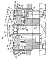
Die einzige Figur veranschaulicht schematisch im Schnitt eine Ausführungsform einer Austrittsdüse nach der Erfindung mit einem Verschließmechanismus und einem Rückspülsystem. Die in der Zeichnung dargestellte Austrittsdüse für das Austrittsventil 34 einer Whirpoolwanne weist einen Ventilkörper 39 mit einem zentral angeordneten Wasserzufuhrkanal 35 auf, welcher mit in einen Austrittskanal 36 radial mündenden Austrittsöffnungen 56 versehen ist. Der Austrittskanal 36 wird durch die Innenfläche 41 eines auf einen mit einer Eingriffnut 68 versehenen Fortsatz 67 des Ventilkörpers 39 aufsteckbaren tellerförmigen Verteilungskörpers 37 und durch eine Oberfläche 44 eines Kolbens 49 gebildet. Dabei verringert sich die Höhe des Austrittskanals 36 von radial innen nach radial außen, indem die Oberfläche 44 des Kolbens 49 von radial innen nach radial außen schräg auf die Wannenwandung 42 zuläuft und die Innenfläche 41 des Verteilungskörpers 37 von einem radial inneren, etwa parallel zur Wannenwandung 42 verlaufenden Abschnitt in einen schräg zu dieser geneigten Bereich übergeht, wodurch am radial außen liegenden Umfang des Austrittskanals 36 eine Austrittsschlitz 45 gebildet ist. Durch diesen sich von radial innen nach radial außen verjüngenden Austrittskanal 36 erhält das aus den Austrittsöffnungen 56 austretende Wasser die erforderliche Geschwindigkeit, um beim Austreten aus dem Austrittsschlitz 45 eine Sogwirkung auf die unmittelbar hinter dem Austrittsschlitz 45 über einen sich axial im Ventilkörper 39 nach oben erstreckenden ggf. Einzelluftzufuhrkanäle 53 aufweisenden Luftzufuhrkanal 38 eingeleitete Luft auszuüben. Die Vermischung des Wassers mit der angesaugten Luft findet in einem sich radial nach außen an den Austrittskanal 36 anschließenden Zwischenraum 46 statt. Dieser Zwischenraum 46 wird durch den äußeren Randbereich der Innenfläche 41 des Verteilungskörpers 37 und die Oberfläche 48 des Kolbens 49 gebildet. Um dem Wasser-Luft-Gemisch eine gewünschte Austrittsrichtung zu geben erstreckt sich der in Art eines Ringkanals ausgebildete Zwischenraum 46 unter geringem Winkel von der Wannenwandung 42 weg. Für eine gute Vermischung des Wassers mit der zugeführten Luft weist der Zwischenraum 46 eine etwa gleichbleibende Breite auf, welche die Breite des Austrittsschlitzes 45 bei dem hier gewählten Ausführungsbeispiel etwa um einen Faktor 2 übersteigt.The single figure schematically illustrates in section an embodiment of an outlet nozzle according to the invention with a closing mechanism and a backwash system. The outlet nozzle shown in the drawing for the
Der die Oberflächen 44 und 48 aufweisende Kolben 49 ist in einem Ringraum 61 des Verntilkörpers 39 aufgenommen mit einem den Wasserzufuhrkanal 35 konzentrisch umgebenden axialen Wandungsbereich 63 und einer sich radial nach außen erstreckenden Auflagefläche 62. Für die axiale Hubbewegung des an dem Ventilgehäuse 40 des Austrittsventils 34 geführten einzähligen Kolbens 49 sind Federkraftspeicher 60 in Form von Gummipuffern vorgesehen, auf welchen der Kolben 49 mit seiner Unterseite gelagert ist und welche sich gegen die Auflagefläche 62 des Ringraumes 61 abstützen. Die beiden den Wasserzufuhrkanal 35 konzentrisch umgebenden ringförmig ausgebildeten Federkraftspeicher 60 sind beidseitig der im Kolben 44 sich axial nach oben erstreckenden und in einen Ringkanal 47 übergehenden Bohrungen 54 des Lufzufuhrkanals 38 angeordnet. Durch diese symmetrische Lagerung wird zum einen ein Verkanten des Kolbens 49 bei seiner Hubbewegung vermieden. Zum anderen ist bei dieser Anordnung der Gummipuffer 60 zwischen Kolben 44 und Auflageflächen 62 des Ventilköpers 49 ein Zwischenraum des Ringraumes 61 gebildet, der von den als Gummipuffer ausgebildeten Federkraftspeichern 60 in zwei flüssigkeits- und/oder gasdicht gegeneinander getrennte Abschnitte 50, 51 aufgeteilt ist, wobei der radial äußere Abschnitt 51 für die Durchleitung von Luft mit den Bohrungen 54 des Kolbens 49 und dem von unten kommenden Abschnitt des Luftzufuhrkanals 38 in Verbindung steht.The
Die Rückstellkraft der Federkraftspeicher 60 ist dabei so zu wählen, daß bei Betrieb des Austrittsventils 34 durch den Druck des über die Austrittsöffnungen 56 austretenden Wassers und unterstützend durch den im Zwischenraum 46 gebildeten Druck des Wasserluftgemisches der Kolben 49 mit seinen Oberflächen 44 und 48 axial nach unten in die Öffnungsstellung gedrückt wird. Ist dagegen das Austrittsventil 34 abgeschlatet, so bewirkt die Rückstellkraft der Federkernspeicher 60 einen axialen Hub des Kolbens 49, wobei der Endbereich seiner Oberfläche 44 sowie seine Oberfläche 48 gegen die Innenfläche 41 des Verteilungskörpers 37 gedrückt werden und damit das Austrittsventil 34 gegen ein Einströmen von Badewasser aus der Whirlpool-Wanne abdichten. Um eine sichere Abdichtung zu gewährleisten und gleichzeitig die mechanische Beanspruchung gering zu halten, sind die in Schließstellung des Kolbens 49 in Anlage mit der Innenfläche 41 des Verteilungskörpers 37 kommenden Abschnitte der Oberflächen 44 und 48 mit einer Dichtleiste 59 versehen. Für die hier gewählte einzählige Kolbenausbildung mit einer die Breite des Austrittsschlitzes 45 übersteigenden Breite des Zwischenraumes 46 weist der Kolben 49 unmittelbar unterhalb des Austrittsschlitzes 45 und in der den Ringspalt 47 für die Zuführung der Luft begrenzenden Kolbenwandung 57 eine Ausnehmung 58 auf, welche in Öffnungsstellung von der angrenzenden Dichtleiste 59 unter Bildung der Unterseite des Austrittsschlitzes 45 überragt wird. In Schließstellung ist die Dichtleiste 59 in die Ausnehmung 58 eingedrückt, wobei der sich dabei ergebende Wulst der Dichtleiste 59 am Knie der Ausnehmung 58 fest an die Innenfläche 41 des Verteilungskörpers 37 angepreßt wird und den Innenraum des Austrittskanals 36 flüssigkeitsdicht abdichtet.The restoring force of the
Dieses Abdichten des Austrittskanals 36, nicht nur gegenüber der Umgebung des Austrittsventils 34, sondern auch gegenüber dem Ringkanal 47 für die zuzuführende Luft ist von besonderem Vorteil für die nach der Erfindung vorgesehene Rückspülung bzw. Reinigung des Austrittsventils 34. Hierfür ist zwischen dem inneren Wandungsbereich 64 des Kolbens 49 und dem zugewandten Wandungsbereich 63 des Ventilkörpers 39 ein den Austrittskanal 36 und den von den Federkraftspeichern 60 freigehaltenen Abschnitt 50 des Ringraumes 61 verbindender Ringspalt 63 vorgesehen. Der Abschnitt 50 des Ringraumes 61 mündet in einen in dem Ventilkörper 39 sich axial nach unten erstreckenden Rücklaufkanal 66, welcher ggf. über ein Absperrorgan mit dem Abfluß der Whirpool-Wanne verbunden ist. Dabei dient der radial innere ringförmige Federkraftspeicher 60 als Abdichtung des radial inneren Abschnittes 50 des Ringraumes durch die Federkraftspeicher 60 freigehaltenen Zwischenraumes des Ringraumes 61 gegenüber dem sich radial nach außen erstreckenden weiteren Abschnitt 51 für die Luftzufuhr, so daß ein Eindringen von Wasser oder Reinigungsflüssigkeit in das Luftzufuhrsystem ausgeschlossen ist. Der Druck der über den Wasserzufuhrkanal 36 zugeführt und über die Austrittsöffnungen 56 in den Austrittskanal 36 eintretenden Spülflüssigkeit ist dabei so einzustellen, daß der Kolben 49 in seiner Schließstellung verbleibt. Damit in Öffnungsstellung des Kolbens 49 kein Wasser über den Ringspalt 63 in den Whirlpool-Abfluß abfließen kann, ist es möglich, den mit dem Abfluß des Whirlpools verbundenen Rücklaufkanal 66 mit einem Absperrorgan zu versehen, welches sich bei dem für die Öffnungsstellung des Kolbens 49 erforderlichen Wasserdrucks selbsttätig verschließt, jedoch bei dem geringeren Druck der Reinigungsflüssigkeit geöffnet ist. Alternativ hierzu kann jedoch auch ohne die Anordnung eines solchen Absperrorgans die Leckrate des bei Betrieb der Austrittsdüse zugeführten Wassers ausreichend gering gehalten wrden, wenn der Ringspalt 63 eine Breite von 0,1 bis 1 mm, vorzugsweise 0,6 mm aufweist.This sealing of the
Mit der erfundenen Austrittsdüse wird ein neuartiges Massagegefühl durch ein intensives, aufgrund der hervorragenden Injektorwirkung anstehendes Wasser-Luft-Gemisch erzeugt, welches im wesentlichen parallel zur Wannenwandung ausströmt und von dem feine Luftblasen im Wannenwasser zur Massage des Wannenbenutzers aufsteigen. Gleichzeitig ermöglicht die erfindungsgemäße Austrittsdüse bei Betriebsstillstand ein selbsttätiges zuverlässiges Abdichten ihres Innenraumes gegenüber dem mit Verunreinigungen beladenen Badewasser des Whirpools, welche sonst zu einer Verschmutzung des Zufuhrsystems und Keimablagerung in diesem führen könnte. Darüber hinaus kann das Zufuhrsystem bei Betriebsstillstand durch Rückspülung mit Wasser oder einer Reinigungsflüssigkeit in vorteilhafter Weise rückgespült werden, ohne daß dabei die Reinigungsflüssigkeit in die Whirpool-Wanne gelangt.With the invented outlet nozzle, a new kind of massage feeling is created by an intensive water-air mixture due to the excellent injector effect, which flows out essentially parallel to the tub wall and from which fine air bubbles rise in the tub water to massage the tub user. At the same time, the outlet nozzle according to the invention enables an automatic, reliable sealing of its interior from the bath water of the whirlpool, which would otherwise lead to contamination of the supply system and germ deposition in the latter, when the operating system is shut down. In addition, the supply system can be backwashed by backwashing with water or a cleaning liquid in an advantageous manner when the plant is at a standstill, without the cleaning liquid getting into the whirlpool bath.
Claims (21)
- An outlet nozzle for the outlet valve (34) of a whirlpool bath with a water supply channel (35) and an air supply channel (38), in which the water current is mixed with the air current by virtue of the injector action, wherein the water supply channel (35) leads into a radially outwardly directed circular-shaped outlet channel (36), which is formed between a plate-shaped distributor body (37) and the valve body (39) of the outlet valve (34), wherein the preferably circular-shaped air supply channel (38, 47, 53, 54) opens into a circular-shaped gap (46), connected radially outwardly to the outlet channel (36), between the plate-shaped distributor body (37) and the valve body (39) or the valve housing (40) or the bath wall (42), and wherein the surfaces (44, 48), forming the outlet channel (36) and/or the gap (46) with the inner face (41) of the distributor body (37), are formed by at least one piston (49) surrounding substantially concentrically the water supply channel (35), and movable relative to the distributor body (37), which piston, when in its closed position, seals in a gas-tight and liquid-tight manner the outlet channel (36) and/or the gap (46) connecting to the outlet channel (36).
- An outlet nozzle according to claim 1, characterised in that at least one piston (49) is carried in the valve body (39) or on the valve housing (40) or on the bath wall (42).
- An outlet nozzle according to claim 1 or 2, characterised in that the air supply channel (38) has individual air supply channels (53), which are in flow connection with bores (54) extending axially in the piston (49).
- An outlet nozzle according to claim 3, characterised in that the bores (54) of the air supply channel (38) lead into an annular channel (47) opening into the gap (46).
- An outlet nozzle according to claim 3 or 4, characterised in that the bores (54) or the annular channel (47) of the air supply channel (38) open or opens directly behind an outlet slot (45) formed in the edge region of the outlet channel (36) into the gap (46).
- An outlet nozzle according to one of claims 1 to 5, characterised in that the faces (41, 44, 48) of the distributor body (37) and of the piston (49), capable of lying against each other in the closed position of the piston (49), at least the regions of the surfaces (44,48) of the piston (49), capable of lying against the inner face (41) of the distributor body (37), are formed as sealing surfaces, possibly with a flexible coating or a layer or lining of rubber or the like.
- An outlet nozzle according to claim 6, characterised in that, in the open position of the piston (49), the surfaces (44, 48) of the piston (49) which reach to the bores (54) or the annular channel (47) of the air supply channel (38) or which extend on both sides of the outlet slot (45) of the outlet channel (36) are arranged in an offset manner, such that the surface (48) defining the gap (46) with the inner face (41) of the distributor body (37) recedes back relative to the surface (44) defining the outlet channel (36), and in that the piston wall (57) in the region of outlet channel slot (45) or of the air supply channel (38), connecting to the surface (44), has a recess, by way of which in the open position of the piston (49) a sealing strip (59) of flexible material connected to the piston surface (44), possibly with formation of the outlet slot (45), extends substantially in the tangential direction to the piston surface (44), which is pressed into the recess (58) in the closed position of the piston (49).
- An outlet nozzle according to one of claims 1 to 7, characterised in that the piston (49) is able to be moved, against the force of a spring force accumulator (60), by means of the force or the pressure of the water flowing out of the water supply channel (35), from the closed position into the open position.
- An outlet nozzle according to claim 8, characterised in that the spring force accumulator (60) is formed by springs, rubber buffers (60) or the like, which are arranged in an annular space (61), surrounding the water supply channel (35) substantially concentrically, between the piston (49) and a bearing face (62) of the valve body (39).
- An outlet nozzle according to claim 9, characterised in that the annular space (61) provided in the valve body (39) has a wall region (63) extending axially upwards from the bearing face (62) for accepting the piston (49) mounted on the spring force accumulator (60), in that an inner wall region (64) of the piston (49), which is arranged concentrically to the water supply channel (35) forms an annular gap (65) with the wall region (63) of the valve body (39) facing it, and in that the annular space (61) opens into a return channel (66) extending axially downwards in the valve body (39), said channel being connected possibly by way of a blocking element with the outflow of the whirlpool bath.
- An outlet nozzle according to claim 10, characterised in that annular rubber buffers (60) are provided, surrounding concentrically the water supply channel (35), and on both sides of the air supply channel (38), which buffers, at least in the closed position of the piston (49), keep free a region of the annular space (61) and in this process divide these into two separate sections (50,51) which are liquid-tight and/or gas-tight with respect to each other, wherein the radially outer section (51) is connected to the air supply channel (38).
- An outlet nozzle according to claim 10 or 11, characterised in that the annular gap (65) has a width of from 0.1 to 1 mm preferably 0.6 mm corresponding to approximately half the width of the outlet slot (45).
- An outlet nozzle according to one of claims 1 to 12, characterised in that the distributor body (37) is held by a bayonet, screw, suction, plug or magnetic connection to the valve body (39) having possibly an axial projection (67) or is formed integrally with said body (39).
- An outlet nozzle according to one of claims 1 to 13, characterised in that the water supply channel (35) in the region of the outlet channel (36) has radially arranged outlet openings (56).
- An outlet nozzle according to one of claims 1 to 14, characterised in that the valve body (39) has an axial projection (67) with an engaging groove (68) for inserting the distributor body (37) possibly made of flexible material.
- An outlet nozzle according to one of claims 1 to 15, characterised in that the inner face (41) of the plate-shaped distributor body (37) runs radially inward then radially outward in the edge region of the outlet channel (36) at a slight angle inclined towards the bath wall (42), forming the radial outlet slot (45).
- An outlet nozzle according to one of claims 1 to 16, characterised in that the inner face (41) of the plate-shaped distributor body (37) extends away with a slight angle from the bath wall (42) in the gap (46) connected to the outlet channel (36).
- An outlet nozzle according to one of claims 1 to 17, characterised in that the inner face (41) of the plate-shaped distributor body (37), in the region of the transition from the outlet channel (36) to the gap (46) forms, with the opposing components of the outlet valve (34), a Venturi groove (43).
- An outlet nozzle according to one of claims 1 to 18, characterised in that the surface (44) of the piston (49) falls away from being radially outward to being radially inwardly inclined to the bath wall (42).
- An outlet nozzle according to one of claims 1 to 19, characterised in that the surface (48) of the piston (49) extends in the region of the gap (46) substantially parallel to the inner face (41) of the distributor body (37), wherein possibly the height of the intermediate space (46) is slightly larger than the width of the outlet slot (45).
- A use of an outlet nozzle according to one of claims 1 to 20, characterised in that its water supply and/or air supply occurs in phases.
Priority Applications (1)
| Application Number | Priority Date | Filing Date | Title |
|---|---|---|---|
| AT87116544T ATE69721T1 (en) | 1986-11-27 | 1987-11-10 | OUTLET NOZZLE FOR THE OUTLET VALVE OF A WHIRLPOOL TUB. |
Applications Claiming Priority (2)
| Application Number | Priority Date | Filing Date | Title |
|---|---|---|---|
| DE19863640497 DE3640497A1 (en) | 1986-11-27 | 1986-11-27 | OUTLET NOZZLE FOR THE OUTLET VALVE OF A WHIRLPOOL TUB |
| DE3640497 | 1986-11-27 |
Publications (3)
| Publication Number | Publication Date |
|---|---|
| EP0270858A2 EP0270858A2 (en) | 1988-06-15 |
| EP0270858A3 EP0270858A3 (en) | 1989-06-07 |
| EP0270858B1 true EP0270858B1 (en) | 1991-11-27 |
Family
ID=6314874
Family Applications (1)
| Application Number | Title | Priority Date | Filing Date |
|---|---|---|---|
| EP87116544A Expired - Lifetime EP0270858B1 (en) | 1986-11-27 | 1987-11-10 | Outlet nozzle for an inlet valve of a whirlpool bath |
Country Status (5)
| Country | Link |
|---|---|
| US (1) | US4896384A (en) |
| EP (1) | EP0270858B1 (en) |
| AT (1) | ATE69721T1 (en) |
| DE (3) | DE8631764U1 (en) |
| ES (1) | ES2028849T3 (en) |
Families Citing this family (41)
| Publication number | Priority date | Publication date | Assignee | Title |
|---|---|---|---|---|
| DE3745018C2 (en) * | 1987-05-06 | 1995-11-23 | Guenter Schuessler | Air-water bubble bath tub |
| EP0376844B1 (en) * | 1988-12-29 | 1994-08-10 | Toto Ltd. | Injection nozzle for automatically varying the volume of water injected |
| ATE107159T1 (en) * | 1988-12-29 | 1994-07-15 | Toto Ltd | SPA TUB WITH INVERTER CONTROLLED CIRCULATION PUMP. |
| US5245714A (en) * | 1988-12-29 | 1993-09-21 | Toto Ltd. | Whirlpool bath provided with hot water blow-off control |
| DE3902117C1 (en) * | 1989-01-25 | 1990-09-13 | Guenter 6074 Roedermark De Schuessler | |
| DE3903477A1 (en) * | 1989-02-06 | 1990-08-09 | Viegener Ii Fa Franz | Mixing housing with rotatably mounted inlet nozzle for whirlpool tubs |
| DE3941006A1 (en) * | 1989-12-12 | 1991-06-13 | Bernd Kellerberg | WHIRLPOOLDUESE |
| DE4005688A1 (en) * | 1990-02-23 | 1991-08-29 | Schuessler Guenter | HYDROMASSAGE NOZZLE WITH DECOMPRESSION ROOM AND DRAINAGE SEQUENCE |
| US5251343A (en) * | 1992-05-05 | 1993-10-12 | Paramount Leisure Industries, Inc. | Swimming pool pop-up fitting |
| FR2692173B1 (en) * | 1992-06-10 | 1994-09-02 | Sames Sa | Device for electrostatic projection of a powder coating product with a rotating ionization head. |
| EP0608140A3 (en) * | 1993-01-22 | 1995-12-13 | Cca Inc | Mechanical foam fire fighting equipment and method. |
| DE9304009U1 (en) * | 1993-03-18 | 1994-02-10 | Schiller Reinhard | Massage nozzle |
| DE4322812C1 (en) * | 1993-07-08 | 1994-09-01 | Altura Leiden Holding | Nozzle for a tub |
| US6351859B1 (en) | 1997-08-19 | 2002-03-05 | John V. Maiuccoro | Hydrotherapy tub coplanar flow |
| US5926865A (en) * | 1997-09-23 | 1999-07-27 | Witinski; Joseph L. | Cover for turbo jet dispensing head employed in swiming pool filtering system |
| US6182303B1 (en) * | 1999-12-16 | 2001-02-06 | Saratoga Spa & Bath Co., Inc. | Multiple slot fluid flow |
| US20030080206A1 (en) * | 2001-03-08 | 2003-05-01 | Thomas Duerr | Powder bell purge tube |
| US6643859B1 (en) * | 2001-05-15 | 2003-11-11 | Saratoga Spa & Bath Co., Inc. | Fluid flow system with flow diverter |
| US6859953B1 (en) * | 2002-09-13 | 2005-03-01 | Steven E. Christensen | Jet propulsion system for spa or jetted bath using control of air draw to Venturi jets with a three-way air control valve |
| US6889921B2 (en) * | 2002-09-30 | 2005-05-10 | Illinois Tool Works Inc. | Bell cup skirt |
| EP1635759A4 (en) * | 2003-05-30 | 2007-10-17 | Kipley Roydon Marks | Bath aeration |
| US7128277B2 (en) | 2003-07-29 | 2006-10-31 | Illinois Tool Works Inc. | Powder bell with secondary charging electrode |
| US20050023385A1 (en) * | 2003-07-29 | 2005-02-03 | Kui-Chiu Kwok | Powder robot gun |
| US20050056212A1 (en) * | 2003-09-15 | 2005-03-17 | Schaupp John F. | Split shroud for coating dispensing equipment |
| ITRE20030091A1 (en) * | 2003-09-29 | 2005-03-30 | American Standard Italia S R L | NOZZLE FOR WHIRLPOOL BATHTUBS. |
| US20050173556A1 (en) * | 2004-02-09 | 2005-08-11 | Kui-Chiu Kwok | Coating dispensing nozzle |
| ITRE20040055A1 (en) | 2004-05-19 | 2004-08-19 | American Standard Europe Bvba | JET FOR WHIRLPOOL BATHS |
| DE202005001403U1 (en) * | 2005-01-28 | 2005-04-07 | Villeroy & Boch | sanitary tub |
| US7246757B2 (en) * | 2005-05-02 | 2007-07-24 | Victor Air Tools Co., Ltd. | Nozzle cover of air brush |
| US7950077B2 (en) | 2005-12-05 | 2011-05-31 | Bowles Fluidics Corporation | Spa jet yielding increased air entrainment rates |
| US9248075B2 (en) * | 2006-04-19 | 2016-02-02 | Michael Spencer | Laminar jet and hydrotherapy bath system |
| GB0625583D0 (en) * | 2006-12-21 | 2007-01-31 | Itw Ltd | Paint spray apparatus |
| US8371517B2 (en) | 2007-06-29 | 2013-02-12 | Illinois Tool Works Inc. | Powder gun deflector |
| US20090020626A1 (en) * | 2007-07-16 | 2009-01-22 | Illinois Tool Works Inc. | Shaping air and bell cup combination |
| US8096264B2 (en) * | 2007-11-30 | 2012-01-17 | Illinois Tool Works Inc. | Repulsion ring |
| US10155233B2 (en) * | 2008-04-09 | 2018-12-18 | Carlisle Fluid Technologies, Inc. | Splash plate retention method and apparatus |
| US20120005819A1 (en) * | 2010-07-09 | 2012-01-12 | As Ip Holdco, L.L.C. | Whirlpool Jet Nozzle Assembly and Jet Apparatus |
| US20140101840A1 (en) * | 2012-10-12 | 2014-04-17 | Lmi Roto, Llc | Spa Jet Face |
| CZ25534U1 (en) * | 2013-01-29 | 2013-06-17 | BERNDORF BÄDERBAU s.r.o. | Multipurpose nozzle |
| CN216949694U (en) * | 2021-12-31 | 2022-07-12 | 上海荣威塑胶工业有限公司 | Water spraying device and overground water pool |
| DE102022000534A1 (en) | 2022-02-11 | 2023-08-17 | Truma Gerätetechnik GmbH & Co. KG | Device for heating a liquid and device for guiding a liquid |
Family Cites Families (20)
| Publication number | Priority date | Publication date | Assignee | Title |
|---|---|---|---|---|
| GB712905A (en) * | 1951-04-25 | 1954-08-04 | L G Mouchel And Partners Ltd | Improvements in or relating to the distribution of water in water-cooling towers |
| CH302791A (en) * | 1951-11-20 | 1954-10-31 | Waltert Sen Xaver | Line system for the supply and discharge of a liquid into or from a container. |
| US3217986A (en) * | 1964-03-20 | 1965-11-16 | Gulf Research Development Co | Nozzle |
| GB1015109A (en) * | 1964-09-23 | 1965-12-31 | Avy Lewis Miller | Swimming pool |
| US3462085A (en) * | 1967-12-01 | 1969-08-19 | Crompton & Knowles Corp | Circular nozzle |
| BE787281A (en) * | 1971-08-19 | 1972-12-01 | Peabody Engineering Corp | PERIPHERAL SPRAY TUBE |
| US4211368A (en) * | 1975-06-09 | 1980-07-08 | Legros Francis R | Device for aerating and chemically activating shower water |
| US3985303A (en) * | 1975-10-09 | 1976-10-12 | Steimle Wayne D | Hydromassage device with directional jet control |
| DE2823253A1 (en) * | 1977-11-30 | 1979-05-31 | Bisa Karl | Aerosol and foam generator - with radial blowing agent jets diverted into annular gap with entrained material |
| US4320541A (en) * | 1979-11-13 | 1982-03-23 | Neenan John S | Method and apparatus for providing a pulsating air/water jet |
| AT374678B (en) * | 1980-05-19 | 1984-05-25 | Dupont Robert | HOLDING VALVE FOR ADJUSTABLE INJECTION |
| US4314670A (en) * | 1980-08-15 | 1982-02-09 | Walsh William A Jun | Variable gas atomization |
| GB2114021B (en) * | 1982-01-19 | 1985-05-22 | Clive Richard Randle | Baths |
| JPS58180255A (en) * | 1982-04-16 | 1983-10-21 | Matsushita Electric Ind Co Ltd | Sprayer |
| US4477026A (en) * | 1982-09-30 | 1984-10-16 | Imperial Underground Sprinkler Co. | Bubbler head structure |
| US4486907A (en) * | 1983-09-12 | 1984-12-11 | Carter Heard L | Self-flushing rotatable pop-up water delivery head for pool cleaning systems |
| US4655394A (en) * | 1984-12-19 | 1987-04-07 | Spraying Systems Co. | Dual purpose foam generating and high pressure nozzle |
| DE3607788A1 (en) * | 1985-04-26 | 1986-12-04 | Günter 6074 Rödermark Schüssler | WATER BASIN WITH AIR SPRAYER |
| IT1200742B (en) * | 1985-09-17 | 1989-01-27 | Teuco Guzzini Srl | BATHTUB WITH PERFECTED HYDROMASSAGE SYSTEM |
| DE3630806A1 (en) * | 1986-09-10 | 1988-03-17 | Schuessler Guenter | Nozzle combination for generating air bubbles in a water basin |
-
1986
- 1986-11-27 DE DE8631764U patent/DE8631764U1/de not_active Expired
- 1986-11-27 DE DE19863640497 patent/DE3640497A1/en active Granted
-
1987
- 1987-11-10 DE DE8787116544T patent/DE3774846D1/en not_active Expired - Fee Related
- 1987-11-10 AT AT87116544T patent/ATE69721T1/en not_active IP Right Cessation
- 1987-11-10 ES ES198787116544T patent/ES2028849T3/en not_active Expired - Lifetime
- 1987-11-10 EP EP87116544A patent/EP0270858B1/en not_active Expired - Lifetime
- 1987-11-17 US US07/122,238 patent/US4896384A/en not_active Expired - Fee Related
Also Published As
| Publication number | Publication date |
|---|---|
| DE3640497C2 (en) | 1990-08-30 |
| DE3640497A1 (en) | 1988-06-09 |
| DE3774846D1 (en) | 1992-01-09 |
| DE8631764U1 (en) | 1987-06-25 |
| EP0270858A3 (en) | 1989-06-07 |
| US4896384A (en) | 1990-01-30 |
| ES2028849T3 (en) | 1992-07-16 |
| ATE69721T1 (en) | 1991-12-15 |
| EP0270858A2 (en) | 1988-06-15 |
Similar Documents
| Publication | Publication Date | Title |
|---|---|---|
| EP0270858B1 (en) | Outlet nozzle for an inlet valve of a whirlpool bath | |
| DE19839248B4 (en) | flush valve | |
| DE2607873C2 (en) | ||
| EP0392238B1 (en) | Dispensing facility for media | |
| EP2918741B1 (en) | Return flow block | |
| EP0526508A1 (en) | Rotor nozzle for a high-pressure cleaning device. | |
| DE2532838C3 (en) | Double seat valve with leak control | |
| DE2609557B2 (en) | Shower head | |
| DE2943074T1 (en) | ||
| DE60020868T2 (en) | Valve system for vehicle flushing system | |
| DE102017203468B4 (en) | Bernoulli suction cups | |
| EP0090090A2 (en) | Method of cleaning the cavities of double seat valves | |
| DE2462474C2 (en) | Sprinkler head | |
| DE1231986B (en) | Valve for controlling brakes | |
| EP1941196A1 (en) | Sanitary reversing valve | |
| DE102019117920A1 (en) | Suction device and method for cleaning a filter | |
| EP0359999A1 (en) | Water mixing valve | |
| EP1180459B1 (en) | Vehicle window cleaning unit | |
| EP0621066B1 (en) | Back washing filter assembly | |
| EP0195389B1 (en) | Tube disconnector | |
| EP0732096A2 (en) | Injection nozzle for a sanitary bath | |
| DE19906869C2 (en) | Installation part for a sanitary outlet fitting | |
| WO1991008728A1 (en) | Whirlpool nozzle | |
| DE3834328C2 (en) | Toilet flush valve | |
| DE2111829C3 (en) | Self-cleaning spray head |
Legal Events
| Date | Code | Title | Description |
|---|---|---|---|
| PUAI | Public reference made under article 153(3) epc to a published international application that has entered the european phase |
Free format text: ORIGINAL CODE: 0009012 |
|
| AK | Designated contracting states |
Kind code of ref document: A2 Designated state(s): AT BE CH DE ES FR GB IT LI LU NL |
|
| 17P | Request for examination filed |
Effective date: 19881126 |
|
| PUAL | Search report despatched |
Free format text: ORIGINAL CODE: 0009013 |
|
| AK | Designated contracting states |
Kind code of ref document: A3 Designated state(s): AT BE CH DE ES FR GB IT LI LU NL |
|
| 17Q | First examination report despatched |
Effective date: 19900509 |
|
| GRAA | (expected) grant |
Free format text: ORIGINAL CODE: 0009210 |
|
| AK | Designated contracting states |
Kind code of ref document: B1 Designated state(s): AT BE CH DE ES FR GB IT LI LU NL |
|
| PG25 | Lapsed in a contracting state [announced via postgrant information from national office to epo] |
Ref country code: BE Effective date: 19911127 |
|
| REF | Corresponds to: |
Ref document number: 69721 Country of ref document: AT Date of ref document: 19911215 Kind code of ref document: T |
|
| REF | Corresponds to: |
Ref document number: 3774846 Country of ref document: DE Date of ref document: 19920109 |
|
| ITF | It: translation for a ep patent filed |
Owner name: BUGNION S.P.A. |
|
| GBT | Gb: translation of ep patent filed (gb section 77(6)(a)/1977) | ||
| ET | Fr: translation filed | ||
| REG | Reference to a national code |
Ref country code: ES Ref legal event code: FG2A Ref document number: 2028849 Country of ref document: ES Kind code of ref document: T3 |
|
| PGFP | Annual fee paid to national office [announced via postgrant information from national office to epo] |
Ref country code: FR Payment date: 19920921 Year of fee payment: 6 |
|
| PLBE | No opposition filed within time limit |
Free format text: ORIGINAL CODE: 0009261 |
|
| STAA | Information on the status of an ep patent application or granted ep patent |
Free format text: STATUS: NO OPPOSITION FILED WITHIN TIME LIMIT |
|
| PGFP | Annual fee paid to national office [announced via postgrant information from national office to epo] |
Ref country code: GB Payment date: 19921016 Year of fee payment: 6 |
|
| PG25 | Lapsed in a contracting state [announced via postgrant information from national office to epo] |
Ref country code: AT Effective date: 19921110 |
|
| 26N | No opposition filed | ||
| PG25 | Lapsed in a contracting state [announced via postgrant information from national office to epo] |
Ref country code: LU Free format text: LAPSE BECAUSE OF NON-PAYMENT OF DUE FEES Effective date: 19921130 Ref country code: LI Effective date: 19921130 Ref country code: CH Effective date: 19921130 |
|
| PGFP | Annual fee paid to national office [announced via postgrant information from national office to epo] |
Ref country code: NL Payment date: 19921130 Year of fee payment: 6 Ref country code: ES Payment date: 19921130 Year of fee payment: 6 |
|
| PGFP | Annual fee paid to national office [announced via postgrant information from national office to epo] |
Ref country code: DE Payment date: 19930124 Year of fee payment: 6 |
|
| REG | Reference to a national code |
Ref country code: CH Ref legal event code: PL |
|
| PG25 | Lapsed in a contracting state [announced via postgrant information from national office to epo] |
Ref country code: GB Effective date: 19931110 |
|
| PG25 | Lapsed in a contracting state [announced via postgrant information from national office to epo] |
Ref country code: ES Free format text: LAPSE BECAUSE OF THE APPLICANT RENOUNCES Effective date: 19931111 |
|
| PG25 | Lapsed in a contracting state [announced via postgrant information from national office to epo] |
Ref country code: NL Effective date: 19940601 |
|
| GBPC | Gb: european patent ceased through non-payment of renewal fee |
Effective date: 19931110 |
|
| NLV4 | Nl: lapsed or anulled due to non-payment of the annual fee | ||
| PG25 | Lapsed in a contracting state [announced via postgrant information from national office to epo] |
Ref country code: FR Effective date: 19940729 |
|
| PG25 | Lapsed in a contracting state [announced via postgrant information from national office to epo] |
Ref country code: DE Effective date: 19940802 |
|
| REG | Reference to a national code |
Ref country code: FR Ref legal event code: ST |
|
| REG | Reference to a national code |
Ref country code: ES Ref legal event code: FD2A Effective date: 20010402 |
|
| PG25 | Lapsed in a contracting state [announced via postgrant information from national office to epo] |
Ref country code: IT Free format text: LAPSE BECAUSE OF NON-PAYMENT OF DUE FEES;WARNING: LAPSES OF ITALIAN PATENTS WITH EFFECTIVE DATE BEFORE 2007 MAY HAVE OCCURRED AT ANY TIME BEFORE 2007. THE CORRECT EFFECTIVE DATE MAY BE DIFFERENT FROM THE ONE RECORDED. Effective date: 20051110 |