EP0267816A1 - Verfahren und Vorrichtung, um die Ecke zweier Textilwerkstücke auf eine Nähmaschine zu introduzieren und positionieren - Google Patents
Verfahren und Vorrichtung, um die Ecke zweier Textilwerkstücke auf eine Nähmaschine zu introduzieren und positionieren Download PDFInfo
- Publication number
- EP0267816A1 EP0267816A1 EP87402134A EP87402134A EP0267816A1 EP 0267816 A1 EP0267816 A1 EP 0267816A1 EP 87402134 A EP87402134 A EP 87402134A EP 87402134 A EP87402134 A EP 87402134A EP 0267816 A1 EP0267816 A1 EP 0267816A1
- Authority
- EP
- European Patent Office
- Prior art keywords
- sliding
- stop
- line
- sewing machine
- seam
- Prior art date
- Legal status (The legal status is an assumption and is not a legal conclusion. Google has not performed a legal analysis and makes no representation as to the accuracy of the status listed.)
- Granted
Links
Images


Classifications
-
- D—TEXTILES; PAPER
- D05—SEWING; EMBROIDERING; TUFTING
- D05B—SEWING
- D05B27/00—Work-feeding means
- D05B27/02—Work-feeding means with feed dogs having horizontal and vertical movements
- D05B27/06—Work-feeding means with feed dogs having horizontal and vertical movements arranged above and below the workpieces
-
- D—TEXTILES; PAPER
- D05—SEWING; EMBROIDERING; TUFTING
- D05B—SEWING
- D05B35/00—Work-feeding or -handling elements not otherwise provided for
- D05B35/10—Edge guides
-
- D—TEXTILES; PAPER
- D05—SEWING; EMBROIDERING; TUFTING
- D05D—INDEXING SCHEME ASSOCIATED WITH SUBCLASSES D05B AND D05C, RELATING TO SEWING, EMBROIDERING AND TUFTING
- D05D2207/00—Use of special elements
- D05D2207/02—Pneumatic or hydraulic devices
- D05D2207/04—Suction or blowing devices
Definitions
- the present invention relates to the automatic introduction of textile pieces under the presser foot of a sewing machine, and more particularly the introduction of two superimposed pieces after adjustment of the two corresponding angles.
- the invention relates to the field of making textile articles, but can more generally relate to all fields where it is necessary to superimpose exactly and assemble two flexible pieces.
- first part (a) is first positioned precisely along the first stop along the side of the angle along which the seam is to be made, then along the reference line along the other side of the angle. The same positioning then occurs for the second part, then the two exactly superimposed parts are moved simultaneously and introduced under the presser foot of the sewing machine.
- the method of the invention allows partially hidden time work, insofar as the operator prepares and introduces the second part while the positioning of the first part takes place according to steps a and b.
- straight stop used above should be taken in a broad sense; it is a means along which the part finishes moving. It can actually be a stop in the usual sense of the term, that is to say a material means against which the side of the part will be forced to stop. But it can also be, according to the method of the invention, an intangible means, a reference line along which side of the room will position.
- the pushing means will have the sole function of pushing the part in the direction of the stop; in the second case, the thrust means will have the additional function of stopping the part along the reference line constituting the stop.
- the pushing means are pneumatic means which consist of nozzles, supplied with compressed air and inclined in the pushing direction of the part.
- the device according to the invention comprises a third sliding plate, substantially parallel to the work plane, located above the second sliding plate, and the pushing means consist of orifices made in the first and said third sliding plate
- the second and the third plate have on the side opposite the stop a slightly curved upward shape to facilitate the introduction of the part in the intervals between, on the one hand the first and second plates (first part) and on the other share the second and third plates (second piece).
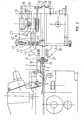
- the edge guide 1 consists of three overlapping plates 2, 3 and 4.
- the lower plate 2 is placed in front of the needle plate 5 so that the upper faces of these two plates 2 and 5 are coplanar. It has several orifices 6, inclined by relative to the horizontal plane and opening into a housing 7 formed in the plate 2 itself, said housing 7 being closed by a plate 8 through which the compressed air inlet 9 is fixed.
- the upper plate 4 also includes orifices 10 supplied with compressed air in the same way as the orifices 6. In both cases, these orifices 6 and 10 are oriented substantially in the direction of the arrow D.
- the plates 2 and 4 are separated from the intermediate plate 3 by means wedges 11 and 12 which constitute the guide bottom stops. The inner parts of shims 11 and 12 forming stops are in the same vertical plane, parallel to the seam line 13 passing through the needle 14.
- Each plate 2 and 4 is partially hollowed out according to a groove, respectively 15 and 16, in which a claw takes place, respectively 17 and 18.
- This groove 15 or 16 allows the claw 17 or 18 to move in its horizontal movement in the direction of the seam line 13.
- Each claw 17 or 18 is connected to a drive device allowing the claw to move vertically and horizontally. This drive device consists of the elements described below.
- stirrups 22 and 23 are fixed on a plate 19, integral with the frame of the sewing machine 20 by means of a hinge with a vertical axis 21.
- Each stirrup receives the elements corresponding to the movements of a claw
- l lower caliper 2 2 receives the elements corresponding to the lower claw 17, the upper caliper 23 those of the upper claw 18.
- the caliper 22 supports on the one hand the stepping motor 24 and on the other hand the axis of rotation 25.
- a pulley 26 is fixed on the axis 25 and is connected to the pulley 27 of the motor 24 by means of the toothed belt 28.
- a support part 29 is articulated around the axis 25; it comprises two guide pin holes 30 and 31 in which the pins 32 and 33 slide fixed on a mechanism 34.
- This mechanism 34 comprises an arm 35, carrying at its end the support 37 of the claw 18, and a rack 38 which meshes with the pinion 39 locked on the axis 25.
- the spring 41 and the adjusting screw 40, fixed on the caliper 2 3, allow an adjustable pressure to be applied to the arm 35 via the part 42 which carries the roller 43, this roller 43 being embedded in the slide 36. This arrangement allows the movement of the arm 35 while maintaining the action spring 41.
- the part lower 44 of the part 42 receives the end of the rod of the jack 45, fixed on the plate 19.
- the edge guide 1 is fixed to the end of the plate 19. In this way the entire device is retractable by pivoting around the axis 21 to allow access to the organs of the sewing machine. blocking, not shown, allows the entire device to be fixed in position.
- a photoelectric cell 46 is placed above the edge guide 1 and in front of the presser foot 47 of the sewing machine.
- the working axis of the cell 46 is vertical and the plates 3 and 4 are drilled to allow the passage of the light flux.
- the photocell 46 is connected to the stepping motor 24.
- Two proximity detectors 47 and 48, placed under the mechanism 34, are also connected to the stepping motor 24.
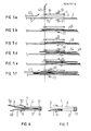
- the first textile piece 49 is introduced manually by the operator in an approximate position; it is pushed towards the stop line 50 in the direction of arrow D, transverse to the seam line 13 (fig 4a). Once the side 51, along which the sewing is to be carried out, positioned exactly along the stop line 50, the first part 49 is moved in the direction of the arrow D ⁇ (fig 4b) until the other side 52 of the angle has reached the reference line 53 (fig. 4c). During the course of this step, the operator manually introduces the second textile piece 54 in an approximate position.
- This second part 54 is also pushed in the direction of arrow D (fig 4c) until the side 55 along which the seam is to be made is positioned exactly along the stop line 50, then (fig 4d ) it is moved along D ⁇ until the other side 56 has reached the reference line 53.
- the two textile pieces 49 and 54 have their two sides (51 and 55), (52 and 56) respectively positioned according to the same lines (50 and 53): these two parts are exactly superimposed.
- the two parts are then simultaneously and at the same speed moved along D ⁇ and introduced under the presser foot 47 of the sewing machine.
- the claws 17 and 18 are in the high position, they are outside the grooves 15 and 16 formed in the plates 2 and 4 (fig 5a).
- the operator manually introduces the first part 49 between the plates 2 and 3, while the compressed air is supplied by the orifices 6 and push the part 49 at the bottom of the guide 1 against the stop 11.
- the action of the air jets is maintained during all the following operations, including sewing.
- the part 49 obscures the photoelectric cell 46.
- the operator presses a control pedal which triggers the retraction of the cylinder 45 ⁇ (from the caliper 22 under the plate 19, corresponding to the cylinder 45 of the caliper 23).
- the retraction of the cylinder 45 ⁇ applies the claw 17 to the part 49 against the underside of the intermediate plate 3.
- the part is thus pinched between the claw 17 and the plate 3 (fig 5b).
- the stepping motor 24 ⁇ starts and drives the claw 17 until the part 49 discovers the cell 46 (fig 5c).
- the side 52 of the part 49 is then positioned along the reference line 53.
- the drive of the claw 17 by the rotation of the stepping motor 24 ⁇ is carried out as follows.
- the pulley 27 ⁇ of the motor 24 ⁇ rotates the axis 25 ⁇ via the toothed belt 28 ⁇ and the pulley 26 ⁇ .
- the pinion 39 ⁇ , mounted on the axis 25 ⁇ turns on itself and causes the displacement of the rack 38 ⁇ , and consequently of the mechanism 34 ⁇ , of the support 37 ⁇ and therefore of the claw 17.
- the mechanism 34 ⁇ is kept horizontal, during of its movement, by the guides 32 ⁇ and 33 ⁇ passing through the guide axes 30 ⁇ and 31 ⁇ .
- the same operations are carried out for the positioning of the second textile piece 54.
- the operator manually introduces this piece 54 between the two plates 3 and 4 of the edge guide 1.
- the area jets, leaving the orifices 10, push the part 54 up to the stop 12 at the bottom of the guide.
- the cell 46 is then again obscured.
- the operator presses on the control pedal which triggers the retraction of the jack 45 and the descent of the claw 18 against the upper face of the intermediate plate 3 (fig 5d).
- the claw 18 moves, driving the part 54 until the cell 46 is again discovered (fig 5e).
- the side 56 of the part 54 is then positioned along the line of reference 53 and the two parts 49 and 54 are exactly superimposed.
- the two stepping motors 24 and 24 ⁇ rotate at a predetermined number of steps in the opposite direction to the previous direction of rotation, which causes the two claws 17 and 18 to move simultaneously and at the same speed. direction of the presser foot 47.
- the number of steps is fixed as a function of the distance separating the reference line 53, marked by the cell 46, and the underside of the presser foot 47. In this way the two parts are introduced, exactly superimposed under the presser foot 47 (fig 5f). Then the jacks 45 and 45 ⁇ come out and move the claws 17 and 18 to their initial position (fig 5a), which position is determined by that of the proximity detectors 47 and 48.
- the air jets coming from the orifices 6 not only push the knitted fabric towards the stop 11 of the bottom of the guide 1 but also unroll the edge before it reaches the bottom of the guide (fig 7).
- the description which has just been made corresponds to a use of the device according to the invention in assistance to an operator for the automatic adjustment and introduction of two angles of parts under the sewing machine.
- the device can also be an automation element in a more complex machine.
Landscapes
- Engineering & Computer Science (AREA)
- Textile Engineering (AREA)
- Sewing Machines And Sewing (AREA)
Priority Applications (1)
| Application Number | Priority Date | Filing Date | Title |
|---|---|---|---|
| AT87402134T ATE66504T1 (de) | 1986-10-03 | 1987-09-24 | Verfahren und vorrichtung, um die ecke zweier textilwerkstuecke auf eine naehmaschine zu introduzieren und positionieren. |
Applications Claiming Priority (2)
| Application Number | Priority Date | Filing Date | Title |
|---|---|---|---|
| FR8613831A FR2604732B1 (fr) | 1986-10-03 | 1986-10-03 | Procede et dispositif d'ajustement et d'introduction automatique de deux angles de pieces textiles sur une machine a coudre |
| FR8613831 | 1986-10-03 |
Publications (2)
| Publication Number | Publication Date |
|---|---|
| EP0267816A1 true EP0267816A1 (de) | 1988-05-18 |
| EP0267816B1 EP0267816B1 (de) | 1991-08-21 |
Family
ID=9339535
Family Applications (1)
| Application Number | Title | Priority Date | Filing Date |
|---|---|---|---|
| EP87402134A Expired - Lifetime EP0267816B1 (de) | 1986-10-03 | 1987-09-24 | Verfahren und Vorrichtung, um die Ecke zweier Textilwerkstücke auf eine Nähmaschine zu introduzieren und positionieren |
Country Status (7)
| Country | Link |
|---|---|
| US (1) | US4825788A (de) |
| EP (1) | EP0267816B1 (de) |
| JP (1) | JPS63164991A (de) |
| AT (1) | ATE66504T1 (de) |
| DE (1) | DE3772330D1 (de) |
| ES (1) | ES2025682T3 (de) |
| FR (1) | FR2604732B1 (de) |
Families Citing this family (3)
| Publication number | Priority date | Publication date | Assignee | Title |
|---|---|---|---|---|
| US8911087B2 (en) | 2011-05-20 | 2014-12-16 | Eyefluence, Inc. | Systems and methods for measuring reactions of head, eyes, eyelids and pupils |
| US8408150B1 (en) | 2011-09-20 | 2013-04-02 | Tenna M. Ragan | Sewing aid |
| CN105133199B (zh) * | 2015-09-08 | 2017-11-28 | 西安标准工业股份有限公司 | 一种带有自动送模板机构的缝纫机及其使用方法 |
Citations (4)
| Publication number | Priority date | Publication date | Assignee | Title |
|---|---|---|---|---|
| US3954071A (en) * | 1973-12-10 | 1976-05-04 | Firma Pfaff Industriemaschinen Gmbh | Sewing machine having top and bottom feed synchronizing means |
| FR2324784A1 (fr) * | 1975-09-17 | 1977-04-15 | Rockwell Rimoldi Spa | Dispositif pour faciliter l'introduction d'un tissu dans le moyen de guidage d'une machine a coudre |
| DE2608859A1 (de) * | 1976-03-04 | 1977-09-08 | Duerkoppwerke | Verstelleinrichtung zum beeinflussen des stoffvorschubes bei der ausfuehrung von naeharbeiten auf einer naehmaschine |
| DE2839399A1 (de) * | 1978-09-11 | 1980-03-20 | Union Special Gmbh | Kantenfuehrung fuer naehmaschinen |
Family Cites Families (6)
| Publication number | Priority date | Publication date | Assignee | Title |
|---|---|---|---|---|
| DE2149069C3 (de) * | 1971-10-01 | 1980-06-04 | Pfaff Industriemaschinen Gmbh, 6750 Kaiserslautern | Nähmaschine mit Einrichtung zum Herstellen von randparallelen Nähten |
| US3867889A (en) * | 1973-08-03 | 1975-02-25 | Stahl Urban Co | Apparatus for seaming pieces of textile fabric or the like |
| IT1049824B (it) * | 1974-12-05 | 1981-02-10 | Pfaff Ind Masch | Impianto di cucitura atto ad unire mediante cucitura strati di stoffa in modo che risultino uniformati in lunghezza |
| CA1065196A (en) * | 1976-03-16 | 1979-10-30 | Siegfried Wajcmann | Sewing apparatus |
| US4037546A (en) * | 1976-07-27 | 1977-07-26 | Union Special G.M.B.H. | Sewing machine apparatus for aligning and sewing pieces of textile fabric or the like |
| DE3441167A1 (de) * | 1983-12-21 | 1985-07-04 | Veb Rationalisierung Konfektion, Ddr 1017 Berlin | Verfahren und vorrichtung zum leichten manipulierbarmachen und deckungsgleichen zufuehren biegeschlaffer flaechenfoermiger werkstuecke insbesondere textiler zuschnitteile zu naeheinrichtungen |
-
1986
- 1986-10-03 FR FR8613831A patent/FR2604732B1/fr not_active Expired
-
1987
- 1987-09-24 AT AT87402134T patent/ATE66504T1/de not_active IP Right Cessation
- 1987-09-24 DE DE8787402134T patent/DE3772330D1/de not_active Expired - Fee Related
- 1987-09-24 ES ES198787402134T patent/ES2025682T3/es not_active Expired - Lifetime
- 1987-09-24 EP EP87402134A patent/EP0267816B1/de not_active Expired - Lifetime
- 1987-10-02 US US07/104,832 patent/US4825788A/en not_active Expired - Fee Related
- 1987-10-02 JP JP62249637A patent/JPS63164991A/ja active Pending
Patent Citations (4)
| Publication number | Priority date | Publication date | Assignee | Title |
|---|---|---|---|---|
| US3954071A (en) * | 1973-12-10 | 1976-05-04 | Firma Pfaff Industriemaschinen Gmbh | Sewing machine having top and bottom feed synchronizing means |
| FR2324784A1 (fr) * | 1975-09-17 | 1977-04-15 | Rockwell Rimoldi Spa | Dispositif pour faciliter l'introduction d'un tissu dans le moyen de guidage d'une machine a coudre |
| DE2608859A1 (de) * | 1976-03-04 | 1977-09-08 | Duerkoppwerke | Verstelleinrichtung zum beeinflussen des stoffvorschubes bei der ausfuehrung von naeharbeiten auf einer naehmaschine |
| DE2839399A1 (de) * | 1978-09-11 | 1980-03-20 | Union Special Gmbh | Kantenfuehrung fuer naehmaschinen |
Also Published As
| Publication number | Publication date |
|---|---|
| ATE66504T1 (de) | 1991-09-15 |
| FR2604732B1 (fr) | 1989-02-03 |
| DE3772330D1 (de) | 1991-09-26 |
| FR2604732A1 (fr) | 1988-04-08 |
| EP0267816B1 (de) | 1991-08-21 |
| ES2025682T3 (es) | 1992-04-01 |
| JPS63164991A (ja) | 1988-07-08 |
| US4825788A (en) | 1989-05-02 |
Similar Documents
| Publication | Publication Date | Title |
|---|---|---|
| FR2666595A1 (fr) | Procede et dispositif pour le retournement et le pliage d'une piece pliable aplatie. | |
| LU82992A1 (fr) | Procede et dispositif pour inserer localement un ruban elastique dans un article textile tel qu'un drap-housse | |
| EP0267816B1 (de) | Verfahren und Vorrichtung, um die Ecke zweier Textilwerkstücke auf eine Nähmaschine zu introduzieren und positionieren | |
| FR2587318A1 (fr) | Procede et machine pour la fabrication de pieces creuses de revolution formees de fils s'etendant selon trois directions differentes. | |
| FR2587377A1 (fr) | Procede d'assemblage et de couture automatique pour pieces de chaussures | |
| FR2715642A1 (fr) | Dispositif pour tourner des pièces reposant à plat pendant leur avance. | |
| FR2655062A1 (fr) | Appareil pour le positionnement automatique de tissus de collant dans une machine a coudre les pieces de collant. | |
| EP0130096A2 (de) | Anlage zur Herstellung von Hemdenmanschetten | |
| EP0534915A1 (de) | Verfahren zum automatischen Zusammennähen zweier Strümpfe zu einer Strumphose und Maschine zur Durchführung des Verfahrens | |
| FR2668778A1 (fr) | Cadre de maintien d'etoffe pour une machine a coudre. | |
| FR2484979A1 (fr) | Procede et appareil d'assemblage de matiere en feuille, notamment pour alimenter en continu des imprimantes rapides | |
| EP0430900A2 (de) | Verfahren und Vorrichtung zum Umwenden von Socken ausserhalb der dazugehörigen Behandlungsmaschine | |
| FR2621610A1 (fr) | Machine a coudre polyvalente | |
| FR2467902A1 (fr) | Dispositif pour la mise automatique en position d'une piece de vetement en vue de l'execution d'une couture | |
| BE1001679A5 (fr) | Appareil pour positionner une chaine de points dans une machine a coudre. | |
| FR2597290A1 (fr) | Procede et appareil de fabrication de faisceaux de conducteurs | |
| FR2684394A1 (fr) | Cadre a broder de machine a broder, deplacable horizontalement. | |
| FR2661428A1 (fr) | Dispositif d'alignement d'une piece d'ouvrage pour une machine a coudre. | |
| JP4108404B2 (ja) | 断裁機の断裁動作切替え機構 | |
| WO1989005368A1 (fr) | Dispositif pour l'insertion automatique d'une bande elastique plate dans les coins d'un drap-housse | |
| FR2521606A1 (fr) | Mecanisme de mise sous tension de matieres en feuille, notamment pour machine a coudre | |
| FR2678649A1 (fr) | Machine a broder. | |
| BE889349A (fr) | Procede et appareil d'assemblage de matiere en feuille, notamment pour alimenter en continu des imprimantes rapides | |
| EP0338909A1 (de) | Werkstückzuführung zu einer Nähmaschine | |
| FR2620652A1 (fr) | Procede et dispositif de positionnement et lacage d'un lien souple sur un support rigide tel qu'un carton |
Legal Events
| Date | Code | Title | Description |
|---|---|---|---|
| PUAI | Public reference made under article 153(3) epc to a published international application that has entered the european phase |
Free format text: ORIGINAL CODE: 0009012 |
|
| AK | Designated contracting states |
Kind code of ref document: A1 Designated state(s): AT BE CH DE ES GB IT LI NL SE |
|
| 17P | Request for examination filed |
Effective date: 19881108 |
|
| 17Q | First examination report despatched |
Effective date: 19901221 |
|
| ITF | It: translation for a ep patent filed |
Owner name: MARCHI & MITTLER S.R.L. |
|
| GRAA | (expected) grant |
Free format text: ORIGINAL CODE: 0009210 |
|
| AK | Designated contracting states |
Kind code of ref document: B1 Designated state(s): AT BE CH DE ES GB IT LI NL SE |
|
| REF | Corresponds to: |
Ref document number: 66504 Country of ref document: AT Date of ref document: 19910915 Kind code of ref document: T |
|
| REF | Corresponds to: |
Ref document number: 3772330 Country of ref document: DE Date of ref document: 19910926 |
|
| PGFP | Annual fee paid to national office [announced via postgrant information from national office to epo] |
Ref country code: NL Payment date: 19910930 Year of fee payment: 5 |
|
| GBT | Gb: translation of ep patent filed (gb section 77(6)(a)/1977) | ||
| PGFP | Annual fee paid to national office [announced via postgrant information from national office to epo] |
Ref country code: GB Payment date: 19911122 Year of fee payment: 5 |
|
| PGFP | Annual fee paid to national office [announced via postgrant information from national office to epo] |
Ref country code: CH Payment date: 19911211 Year of fee payment: 5 |
|
| PGFP | Annual fee paid to national office [announced via postgrant information from national office to epo] |
Ref country code: AT Payment date: 19911219 Year of fee payment: 5 |
|
| PGFP | Annual fee paid to national office [announced via postgrant information from national office to epo] |
Ref country code: ES Payment date: 19911226 Year of fee payment: 5 |
|
| PGFP | Annual fee paid to national office [announced via postgrant information from national office to epo] |
Ref country code: DE Payment date: 19911230 Year of fee payment: 5 Ref country code: SE Payment date: 19911230 Year of fee payment: 5 |
|
| PGFP | Annual fee paid to national office [announced via postgrant information from national office to epo] |
Ref country code: BE Payment date: 19920114 Year of fee payment: 5 |
|
| REG | Reference to a national code |
Ref country code: ES Ref legal event code: FG2A Ref document number: 2025682 Country of ref document: ES Kind code of ref document: T3 |
|
| PLBE | No opposition filed within time limit |
Free format text: ORIGINAL CODE: 0009261 |
|
| STAA | Information on the status of an ep patent application or granted ep patent |
Free format text: STATUS: NO OPPOSITION FILED WITHIN TIME LIMIT |
|
| 26N | No opposition filed | ||
| PG25 | Lapsed in a contracting state [announced via postgrant information from national office to epo] |
Ref country code: GB Effective date: 19920924 Ref country code: AT Effective date: 19920924 |
|
| PG25 | Lapsed in a contracting state [announced via postgrant information from national office to epo] |
Ref country code: ES Free format text: LAPSE BECAUSE OF THE APPLICANT RENOUNCES Effective date: 19920925 Ref country code: SE Effective date: 19920925 |
|
| PG25 | Lapsed in a contracting state [announced via postgrant information from national office to epo] |
Ref country code: BE Effective date: 19920930 Ref country code: LI Effective date: 19920930 Ref country code: CH Effective date: 19920930 |
|
| BERE | Be: lapsed |
Owner name: INSTITUT TEXTILE DE FRANCE Effective date: 19920930 |
|
| PG25 | Lapsed in a contracting state [announced via postgrant information from national office to epo] |
Ref country code: NL Effective date: 19930401 |
|
| NLV4 | Nl: lapsed or anulled due to non-payment of the annual fee | ||
| GBPC | Gb: european patent ceased through non-payment of renewal fee |
Effective date: 19920924 |
|
| REG | Reference to a national code |
Ref country code: CH Ref legal event code: PL |
|
| PG25 | Lapsed in a contracting state [announced via postgrant information from national office to epo] |
Ref country code: DE Effective date: 19930602 |
|
| EUG | Se: european patent has lapsed |
Ref document number: 87402134.8 Effective date: 19930406 |
|
| REG | Reference to a national code |
Ref country code: ES Ref legal event code: FD2A Effective date: 19991007 |
|
| PG25 | Lapsed in a contracting state [announced via postgrant information from national office to epo] |
Ref country code: IT Free format text: LAPSE BECAUSE OF NON-PAYMENT OF DUE FEES;WARNING: LAPSES OF ITALIAN PATENTS WITH EFFECTIVE DATE BEFORE 2007 MAY HAVE OCCURRED AT ANY TIME BEFORE 2007. THE CORRECT EFFECTIVE DATE MAY BE DIFFERENT FROM THE ONE RECORDED. Effective date: 20050924 |