EP0264591A2 - Verfahren zur Vermessung der optischen Achse eines Leitstrahlprojektors und Einrichtung zur Durchführung des Verfahrens - Google Patents
Verfahren zur Vermessung der optischen Achse eines Leitstrahlprojektors und Einrichtung zur Durchführung des Verfahrens Download PDFInfo
- Publication number
- EP0264591A2 EP0264591A2 EP87112608A EP87112608A EP0264591A2 EP 0264591 A2 EP0264591 A2 EP 0264591A2 EP 87112608 A EP87112608 A EP 87112608A EP 87112608 A EP87112608 A EP 87112608A EP 0264591 A2 EP0264591 A2 EP 0264591A2
- Authority
- EP
- European Patent Office
- Prior art keywords
- beacon
- axis
- aperture
- modulator
- optical axis
- Prior art date
- Legal status (The legal status is an assumption and is not a legal conclusion. Google has not performed a legal analysis and makes no representation as to the accuracy of the status listed.)
- Granted
Links
- 238000000034 method Methods 0.000 title claims abstract description 15
- 230000003287 optical effect Effects 0.000 title claims abstract description 8
- 230000005855 radiation Effects 0.000 claims description 5
- 230000005540 biological transmission Effects 0.000 claims description 2
- 238000013461 design Methods 0.000 abstract description 3
- 238000012360 testing method Methods 0.000 description 4
- 239000000047 product Substances 0.000 description 3
- 238000010586 diagram Methods 0.000 description 2
- 238000012545 processing Methods 0.000 description 2
- 238000011161 development Methods 0.000 description 1
- 238000007689 inspection Methods 0.000 description 1
- 238000009434 installation Methods 0.000 description 1
- 239000013589 supplement Substances 0.000 description 1
- 238000001931 thermography Methods 0.000 description 1
Images
Classifications
-
- G—PHYSICS
- G02—OPTICS
- G02B—OPTICAL ELEMENTS, SYSTEMS OR APPARATUS
- G02B23/00—Telescopes, e.g. binoculars; Periscopes; Instruments for viewing the inside of hollow bodies; Viewfinders; Optical aiming or sighting devices
- G02B23/12—Telescopes, e.g. binoculars; Periscopes; Instruments for viewing the inside of hollow bodies; Viewfinders; Optical aiming or sighting devices with means for image conversion or intensification
-
- F—MECHANICAL ENGINEERING; LIGHTING; HEATING; WEAPONS; BLASTING
- F41—WEAPONS
- F41G—WEAPON SIGHTS; AIMING
- F41G3/00—Aiming or laying means
- F41G3/32—Devices for testing or checking
- F41G3/326—Devices for testing or checking for checking the angle between the axis of the gun sighting device and an auxiliary measuring device
-
- G—PHYSICS
- G01—MEASURING; TESTING
- G01B—MEASURING LENGTH, THICKNESS OR SIMILAR LINEAR DIMENSIONS; MEASURING ANGLES; MEASURING AREAS; MEASURING IRREGULARITIES OF SURFACES OR CONTOURS
- G01B11/00—Measuring arrangements characterised by the use of optical techniques
- G01B11/26—Measuring arrangements characterised by the use of optical techniques for measuring angles or tapers; for testing the alignment of axes
- G01B11/27—Measuring arrangements characterised by the use of optical techniques for measuring angles or tapers; for testing the alignment of axes for testing the alignment of axes
- G01B11/272—Measuring arrangements characterised by the use of optical techniques for measuring angles or tapers; for testing the alignment of axes for testing the alignment of axes using photoelectric detection means
-
- G—PHYSICS
- G01—MEASURING; TESTING
- G01M—TESTING STATIC OR DYNAMIC BALANCE OF MACHINES OR STRUCTURES; TESTING OF STRUCTURES OR APPARATUS, NOT OTHERWISE PROVIDED FOR
- G01M11/00—Testing of optical apparatus; Testing structures by optical methods not otherwise provided for
Definitions
- the invention relates to a method for measuring the optical axis of a beacon projector according to the preamble of claim 1.
- the present invention is based on the object of eliminating the disadvantages of the prior art and of substantially simplifying the electronics of the axle harmonization system.
- beacon systems When integrating a beacon transmitter into a sighting system, care must be taken to ensure that the optical axes of both subsystems are aligned parallel to one another with the highest precision and that the axis parallelism is maintained under all operational conditions. For these reasons, the development of beacon systems requires the installation of an automatic axle inspection and alignment system in the floor system.
- the method of the axis test according to the invention now makes it possible to measure the axis of a beacon transmitter, which works according to the known reticle image field modulation method, without complex signal processing.
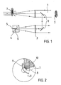
- the guide beam 1 is reflected into the visor 3 via a retroreflector 2 (FIG. 1).
- the optical axis of the visor is a beam splitter cube 4, the back of which bears the line mark 5, while a cross-shaped slit diaphragm 10 with associated radiation detector sits in the conjugate image plane 6.
- the beam splitter cube 4 separates the radiation of the guide beam from the visible radiation in a known manner.
- the center of the crosshead diaphragm 10 is in a mirror-symmetrical position with respect to the crosshair center.
- Fig. 2 shows the shape of the reticle modulator diaphragm 7, which sits in the beam path of the transmitter and generates the specific beacon pattern, consisting of alternately illuminated and dark sectors.
- the circular, backlit area of the modulator diaphragm 7 defines the cross section of the guide beam. It is projected infinitely by the transmitter lens and at the same time imaged by the lens of the visor into the plane of the crosshead aperture 8.
- the center of the modulator diaphragm 7 moves on a circular path 9 about the guide beam axis, which coincides with the axis of the cross-slit diaphragm 10.
- the movement of the modulator diaphragm 7 can be replaced by an opposite movement of the cross-slit diaphragm 10.
- the strength of the radiation signal at the detector is then obtained from the superimposition of the two diaphragm structures.
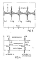
- a gap in the cross-slit aperture 10 is only fully illuminated when the axis of the superimposed, transparent sector of the modulator aperture 7 is just exactly parallel to the corresponding slot axis; in all other positions the slot is switched off about half. If the slot width / length is selected appropriately in relation to the sector width / length, the the signal pulse marking the coincidence is emphasized with respect to all further pulses during a period of the modulator movement (FIG. 3).
Landscapes
- Physics & Mathematics (AREA)
- General Physics & Mathematics (AREA)
- Astronomy & Astrophysics (AREA)
- Optics & Photonics (AREA)
- Chemical & Material Sciences (AREA)
- Analytical Chemistry (AREA)
- Engineering & Computer Science (AREA)
- General Engineering & Computer Science (AREA)
- Optical Radar Systems And Details Thereof (AREA)
- Length Measuring Devices By Optical Means (AREA)
- Aiming, Guidance, Guns With A Light Source, Armor, Camouflage, And Targets (AREA)
Abstract
Description
- Die Erfindung bezieht sich auf ein Verfahren zur Vermessung der optischen Achse eines Leitstrahlprojektors gemäß dem Gattungsbegriff des Anspruchs 1.
- Es sind verschiedene Verfahren bekannt, nach denen die Parallelität der Achsen von Fernrohren, Wärmebildgeräten und Leitstrahlsendern geprüft werden kann. Unabhängig von der Art und Weise, wie dabei die Achsen optisch zur Überlagerung gebracht oder gekoppelt werden, beruhen diese Verfahen auf der punktweisen Abtastung des Leitstrahles durch einen Prüfdetektor; d.h., in der Ebene, in die der zurückreflektierte Leitstrahl fokussiert wird, befindet sich ein Detektor mit Nadellochblende, der vollkommen analog zum Empfänger im Flugkörper einen winzigen Bereich des gesamten Leitstrahles empfängt. Diese Art der Achsprüfung macht es erforderlich, daß die gesamte Ortungselektronik des Empfängers im Flugkörper auch in den Sender eingebaut wird, wodurch dieser an Gewicht, Komplexität und Kosten zunimmt.
- Der vorliegenden Erfindung liegt die Aufgabe zugrunde, die Nachteile des Standes der Technik zu beseitigen und eine wesentliche Vereinfachung der Elektronik des Achsharmonisierungssystems zu ermöglichen.
- Diese Aufgabe wird durch die im Anspruch 1 aufgezeigten Maßnahmen gelöst. In den Unteransprüchen sind die konstruktiven Ausführungsmerkmale angegeben und in der nachfolgenden Beschreibung ist ein Ausführungsbeispiel des vorgeschlagenen Verfahrens und seine konstruktive Konzeption abgehandelt. Die Figuren der Zeichnung ergänzen die Erläuterungen in der Beschreibung. Es zeigen
- Fig. 1 ein Schemabild des beschriebenen Achsharmonisierungsverfahrens und seiner konstruktiven Merkmale,
- Fig. 2 eine schematische Darstellung der vorgeschlagenen Blendenkopfkonfiguration,
- Fig. 3 ein Diagramm für die typische Form des Prüfdetektorsignals,
- Fig. 4 ein Schemabild bezüglich der Signalverarbeitung mit Koinzidenzimpuls, Referenzimpuls und dem entsprechenden Produktsignal.
- Bei der Integration eines Leitstrahlsenders in ein Visiersystem muß darauf geachtet werden, daß die optischen Achsen beider Teilsysteme mit höchster Präzision parallel zueinander ausgerichet sind und daß die Achsparallelität unter allen operationellen Bedingungen erhalten bleibt. Aus diesen Gründen wird bei der Entwicklung von Leitstrahlanlagen der Einbau eines automatischen Achsprüf- und -richtsystems in die Bodenanlage gefordert.
- Das erfindungsgemäße Verfahren der Achsprüfung gestattet es nun, die Achse eines Leitstrahlsenders, der nach dem bekannten Reticle-Bildfeldmodulationsverfahren arbeitet, ohne aufwendige Signalverarbeitung zu vermessen. Zur Erläuterung des Funktionsprinzips sei angenommen, daß der Leitstrahl 1 über einen Retroreflektor 2 in das Visier 3 eingespiegelt wird (Fig. 1). Auf der optischen Achse des Visiers befindet sich ein Strahlteilerwürfel 4, dessen Rückseite die Strichmarke 5 trägt, während in der konjugierten Bildebene 6 eine kreuzförmige Schlitzblende 10 mit zugehörigem Strahlungsdetektor sitzt. Der Strahlteilerwürfel 4 trennt in bekannter Weise die Strahlung des Leitstrahles von der sichtbaren Strahlung ab. Das Zentrum der Kreuzschlitzblende 10 befindet sich in einer zum Fadenkreuzmittelpunkt spiegelsymmetrischen Position.
- Fig. 2 zeigt die Form der Reticle-Modulatorblende 7, die im Strahlengang des Senders sitzt und das spezifische Leitstrahlmuster, bestehend aus abwechselnd ausgeleuchteten und dunklen Sektoren, erzeugt. Der kreisförmige, von hinten beleuchtete Bereich der Modulatorblende 7 definiert den Querschnitt des Leitstrahles. Er wird vom Senderobjektiv nach unendlich projiziert und gleichzeitig vom Objektiv des Visiers in die Ebene der Kreuzschlitzblende 8 abgebildet. Während der Sendephase bewegt sich das Zentrum der Modulatorblende 7 auf einer Kreisbahn 9 um die Leitstrahlachse, die mit der Achse der Kreuzschlitzblende 10 zusammenfällt. Für die Analyse kann man die Bewegung der Modulatorblende 7 durch eine gegensinnige Bewegung der Kreuzschlitzblende 10 ersetzen. Man erhält dann die Stärke des Strahlungssignales am Detektor aus der Überlagerung der beiden Blendenstrukturen. Wie in Fig. 2 zu erkennen, wird ein Spalt der Kreuzschlitzblende 10 nur dann voll ausgeleuchtet, wenn die Achse des überlagerten, transparenten Sektors der Modulatorblende 7 gerade exakt parallel zur entsprechenden Schlitzachse steht; bei allen anderen Stellungen wird der Schlitz etwa zur Hälfte abgeschaltet. Wird die Schlitzbreite/länge im Verhältnis zur Sektorbreite/länge geeignet gewählt, so kann der die Koinzidenz markierende Signalimpuls gegenüber allen weiteren Impulsen während einer Periode der Modulatorbewegung hervorgehoben werden (Fig. 3). Insgesamt treten während einer Umdrehung der Modulatorblende 7 vier Koinzidenzimpulse auf. Markiert man die Stellung der Modulatorblende 7 zum Zeitpunkt t = 0 und nach jeder weiteren Viertelumdrehung durch geeignete Referenzimpulse (Fig. 4), so ist das Produkt aus je einem Koinzidenzimpuls und dem dazugehörigen Referenzimpuls ein Maß für die Abweichung der Leitstrahlachse von ihrer Sollposition (gegeben durch den Kreuzschlitzmittelpunkt). Bei exakter Justierung (Kreuzachse fällt mit der Modulator-Rotationsachse zusammen) verschwindet das gemittelte Produktsignal. Ein positiver/negativer Wert zeigt eine Achsabweichung nach oben/unten bzw. links/rechts an.
Claims (4)
Applications Claiming Priority (2)
| Application Number | Priority Date | Filing Date | Title |
|---|---|---|---|
| DE3635689 | 1986-10-21 | ||
| DE19863635689 DE3635689A1 (de) | 1986-10-21 | 1986-10-21 | Verfahren zur vermessung der optischen achse eines leitstrahlprojektors und einrichtung zur durchfuehrung des verfahrens |
Publications (3)
| Publication Number | Publication Date |
|---|---|
| EP0264591A2 true EP0264591A2 (de) | 1988-04-27 |
| EP0264591A3 EP0264591A3 (en) | 1988-07-06 |
| EP0264591B1 EP0264591B1 (de) | 1991-04-17 |
Family
ID=6312095
Family Applications (1)
| Application Number | Title | Priority Date | Filing Date |
|---|---|---|---|
| EP87112608A Expired - Lifetime EP0264591B1 (de) | 1986-10-21 | 1987-08-29 | Verfahren zur Vermessung der optischen Achse eines Leitstrahlprojektors und Einrichtung zur Durchführung des Verfahrens |
Country Status (5)
| Country | Link |
|---|---|
| US (1) | US4848903A (de) |
| EP (1) | EP0264591B1 (de) |
| BR (1) | BR8704859A (de) |
| DE (2) | DE3635689A1 (de) |
| ES (1) | ES2021655B3 (de) |
Cited By (3)
| Publication number | Priority date | Publication date | Assignee | Title |
|---|---|---|---|---|
| CN102494872A (zh) * | 2011-11-15 | 2012-06-13 | 中国科学院紫金山天文台 | 实时测定天文望远镜指向误差的方法 |
| US8526014B2 (en) | 2008-06-19 | 2013-09-03 | Trimble Navigation Limited | Positioning device and method for detecting a laser beam |
| US10341902B2 (en) | 2015-01-15 | 2019-07-02 | Telefonaktiebolaget Lm Ericsson (Publ) | Method and system relating to handover |
Families Citing this family (3)
| Publication number | Priority date | Publication date | Assignee | Title |
|---|---|---|---|---|
| DE69920273T2 (de) * | 1998-11-12 | 2005-09-22 | Broadcom Corp., Irvine | Integrierte tunerarchitektur |
| JP4005881B2 (ja) * | 2002-08-30 | 2007-11-14 | 株式会社東芝 | 露光装置の検査方法 |
| DE202015002992U1 (de) * | 2015-04-22 | 2016-07-25 | MÖLLER-WEDEL OPTICAL GmbH | System zum Ausrichten einer Blende relativ zu einer optischen Achse |
Family Cites Families (10)
| Publication number | Priority date | Publication date | Assignee | Title |
|---|---|---|---|---|
| US3690594A (en) * | 1964-05-20 | 1972-09-12 | Eltro Gmbh | Method and apparatus for the determination of coordinates |
| FR1516261A (fr) * | 1967-01-27 | 1968-03-08 | Nord Aviation | Procédé de meusre du dépointage d'un appareil optique et dispositif de mesure correspondant |
| US3989385A (en) * | 1974-09-16 | 1976-11-02 | International Business Machines Corporation | Part locating, mask alignment and mask alignment verification system |
| US4014482A (en) * | 1975-04-18 | 1977-03-29 | Mcdonnell Douglas Corporation | Missile director |
| DE2536878C3 (de) * | 1975-08-19 | 1979-09-27 | Siemens Ag, 1000 Berlin Und 8000 Muenchen | Elektrooptisches Rückstrahl-Ortungsgerät, insbesondere Laserentfernungsmesser, mit Justierhilfe |
| GB1569256A (en) * | 1975-11-14 | 1980-06-11 | Sira Institute | Optical apparatus and method |
| JPS5382100A (en) * | 1976-12-02 | 1978-07-20 | Bofors Ab | Optical system |
| DE2821170C2 (de) * | 1978-05-13 | 1986-06-26 | Ernst Leitz Wetzlar Gmbh, 6330 Wetzlar | Einrichtung zum objektivierten Zieleinfang |
| US4300736A (en) * | 1979-08-17 | 1981-11-17 | Raytheon Company | Fire control system |
| DE3439273C1 (de) * | 1984-10-26 | 1985-11-14 | Eltro GmbH, Gesellschaft für Strahlungstechnik, 6900 Heidelberg | Vorrichtung zur Harmonisierung der Sichtlinien zweier Beobachtungsgeraete |
-
1986
- 1986-10-21 DE DE19863635689 patent/DE3635689A1/de active Granted
-
1987
- 1987-08-29 DE DE8787112608T patent/DE3769431D1/de not_active Expired - Fee Related
- 1987-08-29 ES ES87112608T patent/ES2021655B3/es not_active Expired - Lifetime
- 1987-08-29 EP EP87112608A patent/EP0264591B1/de not_active Expired - Lifetime
- 1987-09-22 BR BR8704859A patent/BR8704859A/pt not_active IP Right Cessation
- 1987-10-20 US US07/111,407 patent/US4848903A/en not_active Expired - Fee Related
Cited By (4)
| Publication number | Priority date | Publication date | Assignee | Title |
|---|---|---|---|---|
| US8526014B2 (en) | 2008-06-19 | 2013-09-03 | Trimble Navigation Limited | Positioning device and method for detecting a laser beam |
| US8743376B2 (en) | 2008-06-19 | 2014-06-03 | Trimble Navigation Limited | Surveying instrument and method for detecting a laser beam |
| CN102494872A (zh) * | 2011-11-15 | 2012-06-13 | 中国科学院紫金山天文台 | 实时测定天文望远镜指向误差的方法 |
| US10341902B2 (en) | 2015-01-15 | 2019-07-02 | Telefonaktiebolaget Lm Ericsson (Publ) | Method and system relating to handover |
Also Published As
| Publication number | Publication date |
|---|---|
| EP0264591B1 (de) | 1991-04-17 |
| DE3635689C2 (de) | 1991-01-24 |
| ES2021655B3 (es) | 1991-11-16 |
| EP0264591A3 (en) | 1988-07-06 |
| DE3769431D1 (de) | 1991-05-23 |
| DE3635689A1 (de) | 1988-05-05 |
| US4848903A (en) | 1989-07-18 |
| BR8704859A (pt) | 1988-05-24 |
Similar Documents
| Publication | Publication Date | Title |
|---|---|---|
| EP1669715B1 (de) | Fahrwerkvermessungseinrichtung | |
| DE3426505C2 (de) | ||
| DE2414382C2 (de) | Optische kollimierende Ausrichtungsanordnung | |
| EP2619526B1 (de) | Autokollimationsfernrohr mit kamera | |
| WO2001016573A1 (de) | Einstellgerät für scheinwerfer oder abstandssensor eines fahrzeuges mit ausrichtung zur anfahrachse | |
| DE2143871C2 (de) | Feuerleitvorrichtung zur Richtkorrektur | |
| DE2426785A1 (de) | Vorrichtung zum ausrichten zweier optischer achsen mit hilfe eines kollimators | |
| CH656216A5 (de) | Verfahren und anordnung zur pruefung der uebereinstimmung von visier- und ziellinien. | |
| DE2202172C3 (de) | Anordnung zum automatischen Nachführen | |
| DE2536878A1 (de) | Optronisches system mit einem von einer justierhilfe gebrauch machenden optronischen geraet | |
| EP0264591A2 (de) | Verfahren zur Vermessung der optischen Achse eines Leitstrahlprojektors und Einrichtung zur Durchführung des Verfahrens | |
| EP0429691B1 (de) | Vorrichtung zum Bestimmen der Ablage eines Ziels von einem bestimmten Ort | |
| DE2454883C2 (de) | Einrichtung zur automatischen, fotoelektrischen Auswertung stereoskopischer Bilder | |
| DE1281158B (de) | Optisches Mehrzweck-Messgeraet | |
| EP0027100A1 (de) | Verfahren zur Bestimmung der Stehachsenfehler eines Vermessungsgerätes | |
| DE3329588C1 (de) | Arbeitsverfahren einer aus Lasersender und Wärmebildgerät kombinierten Geräteanordnung sowie eine Vorrichtung hierzu | |
| DE352473C (de) | Vorrichtung zur Ermittlung der Schussentfernung von solchen Luftfahrzeugen, die sich in einer wagerechten Ebene gleichfoermig und geradlinig bewegen | |
| DE2137304C3 (de) | Optische Anordnung zur Fluchtungsund Richtungspritfung | |
| DE308817C (de) | ||
| CH230102A (de) | Verfahren und Einrichtung zur Messung von Geschossgeschwindigkeiten. | |
| DE977689C (de) | Ziel- und Lenkkommandogeraet fuer Lenkflugkoerper | |
| DE2739124B2 (de) | Prüfgerät für Fahrzeugscheinwerfer | |
| DE1548177A1 (de) | Achsfluchtkontroll- und Messeinrichtung | |
| DE19817139A1 (de) | Vorrichtung zum Prüfen von Fahrzeugeinrichtungen | |
| DE2804552A1 (de) | Geraet zum messen der winkelstellung eines messobjektes |
Legal Events
| Date | Code | Title | Description |
|---|---|---|---|
| PUAI | Public reference made under article 153(3) epc to a published international application that has entered the european phase |
Free format text: ORIGINAL CODE: 0009012 |
|
| AK | Designated contracting states |
Kind code of ref document: A2 Designated state(s): DE ES FR GB IT |
|
| PUAL | Search report despatched |
Free format text: ORIGINAL CODE: 0009013 |
|
| AK | Designated contracting states |
Kind code of ref document: A3 Designated state(s): DE ES FR GB IT |
|
| 17P | Request for examination filed |
Effective date: 19881006 |
|
| 17Q | First examination report despatched |
Effective date: 19900212 |
|
| GRAA | (expected) grant |
Free format text: ORIGINAL CODE: 0009210 |
|
| AK | Designated contracting states |
Kind code of ref document: B1 Designated state(s): DE ES FR GB IT |
|
| ET | Fr: translation filed | ||
| GBT | Gb: translation of ep patent filed (gb section 77(6)(a)/1977) | ||
| REF | Corresponds to: |
Ref document number: 3769431 Country of ref document: DE Date of ref document: 19910523 |
|
| ITF | It: translation for a ep patent filed | ||
| PGFP | Annual fee paid to national office [announced via postgrant information from national office to epo] |
Ref country code: GB Payment date: 19910723 Year of fee payment: 5 |
|
| PGFP | Annual fee paid to national office [announced via postgrant information from national office to epo] |
Ref country code: DE Payment date: 19910724 Year of fee payment: 5 |
|
| PGFP | Annual fee paid to national office [announced via postgrant information from national office to epo] |
Ref country code: FR Payment date: 19910807 Year of fee payment: 5 |
|
| PGFP | Annual fee paid to national office [announced via postgrant information from national office to epo] |
Ref country code: ES Payment date: 19910812 Year of fee payment: 5 |
|
| PLBE | No opposition filed within time limit |
Free format text: ORIGINAL CODE: 0009261 |
|
| STAA | Information on the status of an ep patent application or granted ep patent |
Free format text: STATUS: NO OPPOSITION FILED WITHIN TIME LIMIT |
|
| 26N | No opposition filed | ||
| PG25 | Lapsed in a contracting state [announced via postgrant information from national office to epo] |
Ref country code: GB Effective date: 19920829 |
|
| PG25 | Lapsed in a contracting state [announced via postgrant information from national office to epo] |
Ref country code: ES Free format text: LAPSE BECAUSE OF EXPIRATION OF PROTECTION Effective date: 19920831 |
|
| GBPC | Gb: european patent ceased through non-payment of renewal fee |
Effective date: 19920829 |
|
| PG25 | Lapsed in a contracting state [announced via postgrant information from national office to epo] |
Ref country code: FR Effective date: 19930430 |
|
| REG | Reference to a national code |
Ref country code: FR Ref legal event code: ST |
|
| PG25 | Lapsed in a contracting state [announced via postgrant information from national office to epo] |
Ref country code: DE Effective date: 19930803 |
|
| REG | Reference to a national code |
Ref country code: ES Ref legal event code: FD2A Effective date: 19990601 |
|
| PG25 | Lapsed in a contracting state [announced via postgrant information from national office to epo] |
Ref country code: IT Free format text: LAPSE BECAUSE OF NON-PAYMENT OF DUE FEES;WARNING: LAPSES OF ITALIAN PATENTS WITH EFFECTIVE DATE BEFORE 2007 MAY HAVE OCCURRED AT ANY TIME BEFORE 2007. THE CORRECT EFFECTIVE DATE MAY BE DIFFERENT FROM THE ONE RECORDED. Effective date: 20050829 |