EP0264548B1 - Verfahren zum Befestigen von senkrecht stehenden Aussenrippen auf Rohren - Google Patents
Verfahren zum Befestigen von senkrecht stehenden Aussenrippen auf Rohren Download PDFInfo
- Publication number
- EP0264548B1 EP0264548B1 EP87110352A EP87110352A EP0264548B1 EP 0264548 B1 EP0264548 B1 EP 0264548B1 EP 87110352 A EP87110352 A EP 87110352A EP 87110352 A EP87110352 A EP 87110352A EP 0264548 B1 EP0264548 B1 EP 0264548B1
- Authority
- EP
- European Patent Office
- Prior art keywords
- soldering
- fins
- pipe body
- basic pipe
- gap
- Prior art date
- Legal status (The legal status is an assumption and is not a legal conclusion. Google has not performed a legal analysis and makes no representation as to the accuracy of the status listed.)
- Expired - Lifetime
Links
- 238000000034 method Methods 0.000 title claims description 20
- 238000005476 soldering Methods 0.000 claims description 37
- 239000000463 material Substances 0.000 claims description 13
- 238000001816 cooling Methods 0.000 claims description 5
- 229910001220 stainless steel Inorganic materials 0.000 claims description 5
- 239000010935 stainless steel Substances 0.000 claims description 5
- 238000007373 indentation Methods 0.000 claims description 4
- 229910001055 inconels 600 Inorganic materials 0.000 claims description 3
- 238000010438 heat treatment Methods 0.000 claims description 2
- 239000002184 metal Substances 0.000 claims 1
- 230000003014 reinforcing effect Effects 0.000 claims 1
- 229910000679 solder Inorganic materials 0.000 description 4
- 229910001026 inconel Inorganic materials 0.000 description 3
- 238000004519 manufacturing process Methods 0.000 description 2
- 244000089486 Phragmites australis subsp australis Species 0.000 description 1
- 230000001681 protective effect Effects 0.000 description 1
- 230000002787 reinforcement Effects 0.000 description 1
Images

Classifications
-
- B—PERFORMING OPERATIONS; TRANSPORTING
- B23—MACHINE TOOLS; METAL-WORKING NOT OTHERWISE PROVIDED FOR
- B23K—SOLDERING OR UNSOLDERING; WELDING; CLADDING OR PLATING BY SOLDERING OR WELDING; CUTTING BY APPLYING HEAT LOCALLY, e.g. FLAME CUTTING; WORKING BY LASER BEAM
- B23K1/00—Soldering, e.g. brazing, or unsoldering
- B23K1/14—Soldering, e.g. brazing, or unsoldering specially adapted for soldering seams
- B23K1/18—Soldering, e.g. brazing, or unsoldering specially adapted for soldering seams circumferential seams, e.g. of shells
-
- B—PERFORMING OPERATIONS; TRANSPORTING
- B23—MACHINE TOOLS; METAL-WORKING NOT OTHERWISE PROVIDED FOR
- B23K—SOLDERING OR UNSOLDERING; WELDING; CLADDING OR PLATING BY SOLDERING OR WELDING; CUTTING BY APPLYING HEAT LOCALLY, e.g. FLAME CUTTING; WORKING BY LASER BEAM
- B23K1/00—Soldering, e.g. brazing, or unsoldering
- B23K1/19—Soldering, e.g. brazing, or unsoldering taking account of the properties of the materials to be soldered
-
- F—MECHANICAL ENGINEERING; LIGHTING; HEATING; WEAPONS; BLASTING
- F28—HEAT EXCHANGE IN GENERAL
- F28F—DETAILS OF HEAT-EXCHANGE AND HEAT-TRANSFER APPARATUS, OF GENERAL APPLICATION
- F28F1/00—Tubular elements; Assemblies of tubular elements
- F28F1/10—Tubular elements and assemblies thereof with means for increasing heat-transfer area, e.g. with fins, with projections, with recesses
- F28F1/12—Tubular elements and assemblies thereof with means for increasing heat-transfer area, e.g. with fins, with projections, with recesses the means being only outside the tubular element
- F28F1/24—Tubular elements and assemblies thereof with means for increasing heat-transfer area, e.g. with fins, with projections, with recesses the means being only outside the tubular element and extending transversely
- F28F1/30—Tubular elements and assemblies thereof with means for increasing heat-transfer area, e.g. with fins, with projections, with recesses the means being only outside the tubular element and extending transversely the means being attachable to the element
-
- B—PERFORMING OPERATIONS; TRANSPORTING
- B23—MACHINE TOOLS; METAL-WORKING NOT OTHERWISE PROVIDED FOR
- B23K—SOLDERING OR UNSOLDERING; WELDING; CLADDING OR PLATING BY SOLDERING OR WELDING; CUTTING BY APPLYING HEAT LOCALLY, e.g. FLAME CUTTING; WORKING BY LASER BEAM
- B23K2101/00—Articles made by soldering, welding or cutting
- B23K2101/04—Tubular or hollow articles
- B23K2101/06—Tubes
- B23K2101/08—Tubes finned or ribbed
-
- Y—GENERAL TAGGING OF NEW TECHNOLOGICAL DEVELOPMENTS; GENERAL TAGGING OF CROSS-SECTIONAL TECHNOLOGIES SPANNING OVER SEVERAL SECTIONS OF THE IPC; TECHNICAL SUBJECTS COVERED BY FORMER USPC CROSS-REFERENCE ART COLLECTIONS [XRACs] AND DIGESTS
- Y10—TECHNICAL SUBJECTS COVERED BY FORMER USPC
- Y10T—TECHNICAL SUBJECTS COVERED BY FORMER US CLASSIFICATION
- Y10T29/00—Metal working
- Y10T29/49—Method of mechanical manufacture
- Y10T29/4935—Heat exchanger or boiler making
- Y10T29/49377—Tube with heat transfer means
- Y10T29/49378—Finned tube
Definitions
- the present invention relates to a method according to the preamble of patent claim 1.
- DE-A1 1 950 471 describes a method for attaching transverse fins to pipes, the pipe being expanded and at the same time a soldered connection being made between the expanded pipe and the fin. Furthermore, the application of an overpressure in a tube from GB-A 1 317 983 and FR-A 1 568 993 is known for soldering.
- Soldering stiffening ribs in a soldering oven under vacuum or protective gas can only work properly if the soldering gap between the stiffening ribs and the tube is very small at the soldering temperature, i.e. is less than 0.1 mm. Since then, the problem has been solved in that, before the soldering, the jet pipe was mechanically widened by means of a spreading tool and the pipe should thus be in contact with the ribs.
- a mechanical or hydraulic mechanical expanding tool is, however, technically very complex, so that this method can no longer be carried out or can only be carried out with considerable effort for any pipe cross-sectional shapes.
- the fact that the mechanical spreading takes place before the soldering does not guarantee that the narrow soldering gap is also present during the soldering. For example, the distortion of the tube at high soldering temperatures.
- soldering gaps should generally be kept as small as possible. This is opposed to the fact that the corresponding holes or negative shapes in the ribs are very precise, but the tube shape or the corresponding positive shape can only be produced with deviations of greater than or equal to ⁇ 0.1 mm due to production. When choosing the same materials, it is also difficult to maintain small soldering gaps.
- the outer circumference of the main body of the jet pipe and the circumference of the corresponding opening in the ribs should match exactly. If there were any errors, the ribs would no longer be able to be threaded onto the tube base body, and the result would be undesirable scratch marks into which the solder can shoot and would not be stopped.
- the present invention therefore has the task of specifying a method in which the required narrow soldering gap can be generated and guaranteed during soldering, so that a perfect connection between the tube body and the rib is ensured without bulging the tube wall.
- the present invention now proposes the method steps that are listed in claim 1. Particularly advantageous parameters for the method according to the invention are specified in claim 2.
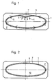
- FIG. 1 shows the indentation 3 of the oval tube base body 1 of a jet tube for vacuum operation of UHV, on which reinforcement or cooling fins were soldered with their inner contour 7 after being simply plugged on.
- the buckling in the direction of the arrows 4 causes the circumferential tension 5, which arises during the soldering due to the heating, the process is favored by certain previous damage, e.g. by dents or if the solder gap 6 has been chosen too narrow from the outset.
- FIG. 2 shows a perfect connection between the tube body 1 and the ribs 2.
- the soldering gap 6 exactly follows the inner contour 7, the ribs 2 are soldered onto the base body without indentation.
- FIG. 3 particularly suitable materials are now shown as a family of curves of their linear thermal expansion coefficients.
- Curve 8 shows the coefficients of stainless steel material No. 1.4301, curves 9 the corresponding coefficients for Inconel 601, 600 and 625. From curves 8 and 9 it can be seen that the correspondingly higher coefficients of stainless steel according to curve 8 compared to the lower of Inconel of curve 9 favor contact of the tubular body 1 with the inner contour 7 of the cooling fins 2.
- the process is characterized in particular by the fact that the combination of gas overpressure in the tube and the use of different materials for the components means that the play between the ribs and the tube when threading the ribs can be relatively large and by the different thermal expansion of the material pairing of the soldering gap at the soldering temperature becomes almost 0.
Landscapes
- Engineering & Computer Science (AREA)
- Mechanical Engineering (AREA)
- Physics & Mathematics (AREA)
- Chemical & Material Sciences (AREA)
- Materials Engineering (AREA)
- Geometry (AREA)
- Thermal Sciences (AREA)
- General Engineering & Computer Science (AREA)
- Particle Accelerators (AREA)
- Non-Disconnectible Joints And Screw-Threaded Joints (AREA)
- Details Of Heat-Exchange And Heat-Transfer (AREA)
Applications Claiming Priority (2)
| Application Number | Priority Date | Filing Date | Title |
|---|---|---|---|
| DE19863636198 DE3636198A1 (de) | 1986-10-24 | 1986-10-24 | Verfahren zum befestigen von senkrecht stehenden aussenrippen auf rohren |
| DE3636198 | 1986-10-24 |
Publications (3)
| Publication Number | Publication Date |
|---|---|
| EP0264548A2 EP0264548A2 (de) | 1988-04-27 |
| EP0264548A3 EP0264548A3 (en) | 1988-10-12 |
| EP0264548B1 true EP0264548B1 (de) | 1990-04-04 |
Family
ID=6312384
Family Applications (1)
| Application Number | Title | Priority Date | Filing Date |
|---|---|---|---|
| EP87110352A Expired - Lifetime EP0264548B1 (de) | 1986-10-24 | 1987-07-17 | Verfahren zum Befestigen von senkrecht stehenden Aussenrippen auf Rohren |
Country Status (3)
| Country | Link |
|---|---|
| US (1) | US4815651A (enExample) |
| EP (1) | EP0264548B1 (enExample) |
| DE (1) | DE3636198A1 (enExample) |
Families Citing this family (3)
| Publication number | Priority date | Publication date | Assignee | Title |
|---|---|---|---|---|
| DE4039292A1 (de) * | 1990-12-08 | 1992-06-11 | Gea Luftkuehler Happel Gmbh | Verfahren zum herstellen eines waermetauschers und vorrichtung zur durchfuehrung des verfahrens |
| DE4446563A1 (de) * | 1994-12-24 | 1996-06-27 | Behr Gmbh & Co | Wärmetauscher und Verfahren zu dessen Herstellung |
| US5604982A (en) * | 1995-06-05 | 1997-02-25 | General Motors Corporation | Method for mechanically expanding elliptical tubes |
Family Cites Families (10)
| Publication number | Priority date | Publication date | Assignee | Title |
|---|---|---|---|---|
| US1970481A (en) * | 1933-03-09 | 1934-08-14 | Young Radiator Co | Process of bonding fins to radiator tubes |
| GB821046A (en) * | 1954-10-13 | 1959-09-30 | Vits Elektro G M B H | Ribbed pipes for heat exchangers |
| FR1568993A (enExample) * | 1968-03-19 | 1969-05-30 | ||
| DE1950471A1 (de) * | 1969-10-07 | 1971-04-22 | Ver Deutsche Metallwerke Ag | Verfahren zum Befestigen von Querrippen auf Rohren |
| JPS4933262B1 (enExample) * | 1969-11-25 | 1974-09-05 | ||
| US4002285A (en) * | 1976-03-24 | 1977-01-11 | General Electric Company | Method of metallurgically joining tubing |
| AT362980B (de) * | 1979-09-07 | 1981-06-25 | Metall Und Erz Aktiengesellsch | Verfahren und vorrichtung zur herstellung von waermetauschern |
| GB2085785A (en) * | 1980-10-22 | 1982-05-06 | Serck Industries Ltd | Methods of securing a hollow elongate member in an opening in a further member |
| DE3432073A1 (de) * | 1984-08-31 | 1986-03-06 | Dirk Dipl.-Wirtsch.-Ing. 3500 Kassel Pietzcker | Waermetauscher, insbesondere fuer kraftfahrzeuge, und vorrichtung und verfahren zum verbinden von dessen rohren und lamellen |
| US4570317A (en) * | 1985-01-18 | 1986-02-18 | Ford Motor Company | Method of attaching a tube to a fin |
-
1986
- 1986-10-24 DE DE19863636198 patent/DE3636198A1/de active Granted
-
1987
- 1987-07-17 EP EP87110352A patent/EP0264548B1/de not_active Expired - Lifetime
- 1987-10-26 US US07/112,238 patent/US4815651A/en not_active Expired - Fee Related
Also Published As
| Publication number | Publication date |
|---|---|
| US4815651A (en) | 1989-03-28 |
| EP0264548A2 (de) | 1988-04-27 |
| EP0264548A3 (en) | 1988-10-12 |
| DE3636198C2 (enExample) | 1990-01-18 |
| DE3636198A1 (de) | 1988-04-28 |
Similar Documents
| Publication | Publication Date | Title |
|---|---|---|
| DE3314264C2 (de) | Verfahren zur Herstellung von Stahl-Verbundrohren | |
| DE3221887C2 (de) | Verfahren zum Herstellen von Bimetallrohren | |
| DE1900322A1 (de) | Verfahren zum Herstellen von Verbindungen | |
| DE2648877C3 (de) | Verfahren zum Herstellen von Rohren | |
| DE19531035C2 (de) | Verfahren zur Herstellung von Hohlkörpern aus Aluminium oder Aluminiumlegierungen | |
| DE2926357A1 (de) | Auspuffdichtung | |
| DE2607755A1 (de) | Verfahren zum kaltwalzen einer kontur in metallringen | |
| DE3636198C2 (enExample) | ||
| DE19820124C2 (de) | Verfahren zur Herstellung eines Rohres zur Verwendung in einem Lenkgestänge | |
| DE2208677A1 (de) | Verfahren zur Herstellung eines dünnwandigen röhrenförmigen Körpers | |
| DE2624872C3 (de) | Verfahren zum Herstellen von ungeteilten Felgen | |
| DE3200631C2 (enExample) | ||
| DE2634515A1 (de) | Verfahren zum herstellen von z.b. ungeteilten felgen | |
| CH685432A5 (de) | Kokille zum Stranggiessen von Metall, insbesondere von Stahl in Knüppel- und Vorblockquerschnitte. | |
| DE2227915A1 (de) | Verfahren zur heissausformung pilzfoermiger metallteile | |
| DE540246C (de) | Verfahren zur Herstellung von hochelastischen Well- oder Federrohren | |
| DE863641C (de) | Verfahren zur Herstellung von hochelastischen Federkoerpern | |
| DE2738862C2 (de) | Verfahren zur Herstellung von dünnwandigen Zweikanalrohren | |
| DE2758138C2 (de) | Verfahren zur Herstellung von Präzisionsstahlrohren aus einzeln abgelängtem Blechmaterial | |
| DE961343C (de) | Verfahren zur Herstellung mehrerer in der gleichen Hoehe bzw. der gleichen Querschnittsebene liegender Anschlussstutzen an einem Rohr | |
| DE1475636C3 (de) | Verfahren zur Herstellung eines Wellrohres | |
| DE2253948C2 (de) | Verfahren zum Herstellen einer trommelförmigen Gitterkonstruktion | |
| AT201253B (de) | Verfahren zum Herstellen von aus Glas gefertigten, an einem Ende geschlossenen hohlen Körpern, insbesondere zum Herstellen von Kolben von Entladungsröhren, und Werkzeug zur Durchführung des Verfahrens | |
| DE1135405B (de) | Verfahren zum Herstellen von fluessigkeitsgekuehlten Raketenbrennkammern | |
| DE866187C (de) | Verfahren zur Herstellung von plattiertem Material, insbesondere Stahlkupferdraehten |
Legal Events
| Date | Code | Title | Description |
|---|---|---|---|
| PUAI | Public reference made under article 153(3) epc to a published international application that has entered the european phase |
Free format text: ORIGINAL CODE: 0009012 |
|
| AK | Designated contracting states |
Kind code of ref document: A2 Designated state(s): CH FR GB IT LI |
|
| PUAL | Search report despatched |
Free format text: ORIGINAL CODE: 0009013 |
|
| AK | Designated contracting states |
Kind code of ref document: A3 Designated state(s): CH FR GB IT LI |
|
| 17P | Request for examination filed |
Effective date: 19880902 |
|
| 17Q | First examination report despatched |
Effective date: 19890130 |
|
| ITF | It: translation for a ep patent filed | ||
| GRAA | (expected) grant |
Free format text: ORIGINAL CODE: 0009210 |
|
| AK | Designated contracting states |
Kind code of ref document: B1 Designated state(s): CH FR GB IT LI |
|
| ET | Fr: translation filed | ||
| GBT | Gb: translation of ep patent filed (gb section 77(6)(a)/1977) | ||
| PLBE | No opposition filed within time limit |
Free format text: ORIGINAL CODE: 0009261 |
|
| STAA | Information on the status of an ep patent application or granted ep patent |
Free format text: STATUS: NO OPPOSITION FILED WITHIN TIME LIMIT |
|
| 26N | No opposition filed | ||
| ITTA | It: last paid annual fee | ||
| PGFP | Annual fee paid to national office [announced via postgrant information from national office to epo] |
Ref country code: CH Payment date: 19920526 Year of fee payment: 6 |
|
| PG25 | Lapsed in a contracting state [announced via postgrant information from national office to epo] |
Ref country code: LI Effective date: 19930731 Ref country code: CH Effective date: 19930731 |
|
| PGFP | Annual fee paid to national office [announced via postgrant information from national office to epo] |
Ref country code: GB Payment date: 19930812 Year of fee payment: 7 |
|
| PGFP | Annual fee paid to national office [announced via postgrant information from national office to epo] |
Ref country code: FR Payment date: 19930930 Year of fee payment: 7 |
|
| REG | Reference to a national code |
Ref country code: CH Ref legal event code: PL |
|
| PG25 | Lapsed in a contracting state [announced via postgrant information from national office to epo] |
Ref country code: GB Effective date: 19940717 |
|
| GBPC | Gb: european patent ceased through non-payment of renewal fee |
Effective date: 19940717 |
|
| PG25 | Lapsed in a contracting state [announced via postgrant information from national office to epo] |
Ref country code: FR Effective date: 19950331 |
|
| REG | Reference to a national code |
Ref country code: FR Ref legal event code: ST |
|
| PG25 | Lapsed in a contracting state [announced via postgrant information from national office to epo] |
Ref country code: IT Free format text: LAPSE BECAUSE OF NON-PAYMENT OF DUE FEES;WARNING: LAPSES OF ITALIAN PATENTS WITH EFFECTIVE DATE BEFORE 2007 MAY HAVE OCCURRED AT ANY TIME BEFORE 2007. THE CORRECT EFFECTIVE DATE MAY BE DIFFERENT FROM THE ONE RECORDED. Effective date: 20050717 |