EP0264147B1 - Vorrichtung zur Feinverstellung und Vorrichtung zum Steuern dieser Verstellungen - Google Patents
Vorrichtung zur Feinverstellung und Vorrichtung zum Steuern dieser Verstellungen Download PDFInfo
- Publication number
- EP0264147B1 EP0264147B1 EP87201701A EP87201701A EP0264147B1 EP 0264147 B1 EP0264147 B1 EP 0264147B1 EP 87201701 A EP87201701 A EP 87201701A EP 87201701 A EP87201701 A EP 87201701A EP 0264147 B1 EP0264147 B1 EP 0264147B1
- Authority
- EP
- European Patent Office
- Prior art keywords
- axis
- beam displacement
- flexible
- outwardly
- extending
- Prior art date
- Legal status (The legal status is an assumption and is not a legal conclusion. Google has not performed a legal analysis and makes no representation as to the accuracy of the status listed.)
- Expired - Lifetime
Links
- 238000006073 displacement reaction Methods 0.000 title claims description 413
- 230000007246 mechanism Effects 0.000 claims description 221
- 238000005452 bending Methods 0.000 claims description 3
- 210000002105 tongue Anatomy 0.000 description 11
- 239000000463 material Substances 0.000 description 6
- 239000002184 metal Substances 0.000 description 6
- 238000004519 manufacturing process Methods 0.000 description 4
- 239000004065 semiconductor Substances 0.000 description 3
- 239000011324 bead Substances 0.000 description 2
- 238000010276 construction Methods 0.000 description 2
- 230000008030 elimination Effects 0.000 description 2
- 238000003379 elimination reaction Methods 0.000 description 2
- 238000005516 engineering process Methods 0.000 description 2
- 230000007306 turnover Effects 0.000 description 2
- 238000010894 electron beam technology Methods 0.000 description 1
- 230000010354 integration Effects 0.000 description 1
- 238000000034 method Methods 0.000 description 1
- 230000003287 optical effect Effects 0.000 description 1
Images


Classifications
-
- B—PERFORMING OPERATIONS; TRANSPORTING
- B23—MACHINE TOOLS; METAL-WORKING NOT OTHERWISE PROVIDED FOR
- B23Q—DETAILS, COMPONENTS, OR ACCESSORIES FOR MACHINE TOOLS, e.g. ARRANGEMENTS FOR COPYING OR CONTROLLING; MACHINE TOOLS IN GENERAL CHARACTERISED BY THE CONSTRUCTION OF PARTICULAR DETAILS OR COMPONENTS; COMBINATIONS OR ASSOCIATIONS OF METAL-WORKING MACHINES, NOT DIRECTED TO A PARTICULAR RESULT
- B23Q1/00—Members which are comprised in the general build-up of a form of machine, particularly relatively large fixed members
- B23Q1/25—Movable or adjustable work or tool supports
- B23Q1/26—Movable or adjustable work or tool supports characterised by constructional features relating to the co-operation of relatively movable members; Means for preventing relative movement of such members
- B23Q1/34—Relative movement obtained by use of deformable elements, e.g. piezoelectric, magnetostrictive, elastic or thermally-dilatable elements
- B23Q1/36—Springs
-
- B—PERFORMING OPERATIONS; TRANSPORTING
- B23—MACHINE TOOLS; METAL-WORKING NOT OTHERWISE PROVIDED FOR
- B23Q—DETAILS, COMPONENTS, OR ACCESSORIES FOR MACHINE TOOLS, e.g. ARRANGEMENTS FOR COPYING OR CONTROLLING; MACHINE TOOLS IN GENERAL CHARACTERISED BY THE CONSTRUCTION OF PARTICULAR DETAILS OR COMPONENTS; COMBINATIONS OR ASSOCIATIONS OF METAL-WORKING MACHINES, NOT DIRECTED TO A PARTICULAR RESULT
- B23Q15/00—Automatic control or regulation of feed movement, cutting velocity or position of tool or work
- B23Q15/20—Automatic control or regulation of feed movement, cutting velocity or position of tool or work before or after the tool acts upon the workpiece
- B23Q15/22—Control or regulation of position of tool or workpiece
- B23Q15/24—Control or regulation of position of tool or workpiece of linear position
-
- G—PHYSICS
- G05—CONTROLLING; REGULATING
- G05B—CONTROL OR REGULATING SYSTEMS IN GENERAL; FUNCTIONAL ELEMENTS OF SUCH SYSTEMS; MONITORING OR TESTING ARRANGEMENTS FOR SUCH SYSTEMS OR ELEMENTS
- G05B19/00—Programme-control systems
- G05B19/02—Programme-control systems electric
- G05B19/18—Numerical control [NC], i.e. automatically operating machines, in particular machine tools, e.g. in a manufacturing environment, so as to execute positioning, movement or co-ordinated operations by means of programme data in numerical form
- G05B19/19—Numerical control [NC], i.e. automatically operating machines, in particular machine tools, e.g. in a manufacturing environment, so as to execute positioning, movement or co-ordinated operations by means of programme data in numerical form characterised by positioning or contouring control systems, e.g. to control position from one programmed point to another or to control movement along a programmed continuous path
- G05B19/21—Numerical control [NC], i.e. automatically operating machines, in particular machine tools, e.g. in a manufacturing environment, so as to execute positioning, movement or co-ordinated operations by means of programme data in numerical form characterised by positioning or contouring control systems, e.g. to control position from one programmed point to another or to control movement along a programmed continuous path using an incremental digital measuring device
- G05B19/23—Numerical control [NC], i.e. automatically operating machines, in particular machine tools, e.g. in a manufacturing environment, so as to execute positioning, movement or co-ordinated operations by means of programme data in numerical form characterised by positioning or contouring control systems, e.g. to control position from one programmed point to another or to control movement along a programmed continuous path using an incremental digital measuring device for point-to-point control
-
- H—ELECTRICITY
- H02—GENERATION; CONVERSION OR DISTRIBUTION OF ELECTRIC POWER
- H02N—ELECTRIC MACHINES NOT OTHERWISE PROVIDED FOR
- H02N2/00—Electric machines in general using piezoelectric effect, electrostriction or magnetostriction
- H02N2/0095—Electric machines in general using piezoelectric effect, electrostriction or magnetostriction producing combined linear and rotary motion, e.g. multi-direction positioners
-
- H—ELECTRICITY
- H02—GENERATION; CONVERSION OR DISTRIBUTION OF ELECTRIC POWER
- H02N—ELECTRIC MACHINES NOT OTHERWISE PROVIDED FOR
- H02N2/00—Electric machines in general using piezoelectric effect, electrostriction or magnetostriction
- H02N2/02—Electric machines in general using piezoelectric effect, electrostriction or magnetostriction producing linear motion, e.g. actuators; Linear positioners ; Linear motors
- H02N2/028—Electric machines in general using piezoelectric effect, electrostriction or magnetostriction producing linear motion, e.g. actuators; Linear positioners ; Linear motors along multiple or arbitrary translation directions, e.g. XYZ stages
-
- H—ELECTRICITY
- H02—GENERATION; CONVERSION OR DISTRIBUTION OF ELECTRIC POWER
- H02N—ELECTRIC MACHINES NOT OTHERWISE PROVIDED FOR
- H02N2/00—Electric machines in general using piezoelectric effect, electrostriction or magnetostriction
- H02N2/02—Electric machines in general using piezoelectric effect, electrostriction or magnetostriction producing linear motion, e.g. actuators; Linear positioners ; Linear motors
- H02N2/06—Drive circuits; Control arrangements or methods
- H02N2/062—Small signal circuits; Means for controlling position or derived quantities, e.g. for removing hysteresis
-
- H—ELECTRICITY
- H02—GENERATION; CONVERSION OR DISTRIBUTION OF ELECTRIC POWER
- H02N—ELECTRIC MACHINES NOT OTHERWISE PROVIDED FOR
- H02N2/00—Electric machines in general using piezoelectric effect, electrostriction or magnetostriction
- H02N2/10—Electric machines in general using piezoelectric effect, electrostriction or magnetostriction producing rotary motion, e.g. rotary motors
- H02N2/108—Electric machines in general using piezoelectric effect, electrostriction or magnetostriction producing rotary motion, e.g. rotary motors around multiple axes of rotation, e.g. spherical rotor motors
-
- B—PERFORMING OPERATIONS; TRANSPORTING
- B82—NANOTECHNOLOGY
- B82Y—SPECIFIC USES OR APPLICATIONS OF NANOSTRUCTURES; MEASUREMENT OR ANALYSIS OF NANOSTRUCTURES; MANUFACTURE OR TREATMENT OF NANOSTRUCTURES
- B82Y35/00—Methods or apparatus for measurement or analysis of nanostructures
-
- G—PHYSICS
- G05—CONTROLLING; REGULATING
- G05B—CONTROL OR REGULATING SYSTEMS IN GENERAL; FUNCTIONAL ELEMENTS OF SUCH SYSTEMS; MONITORING OR TESTING ARRANGEMENTS FOR SUCH SYSTEMS OR ELEMENTS
- G05B2219/00—Program-control systems
- G05B2219/30—Nc systems
- G05B2219/41—Servomotor, servo controller till figures
- G05B2219/41133—Compensation non linear transfer function
-
- G—PHYSICS
- G05—CONTROLLING; REGULATING
- G05B—CONTROL OR REGULATING SYSTEMS IN GENERAL; FUNCTIONAL ELEMENTS OF SUCH SYSTEMS; MONITORING OR TESTING ARRANGEMENTS FOR SUCH SYSTEMS OR ELEMENTS
- G05B2219/00—Program-control systems
- G05B2219/30—Nc systems
- G05B2219/41—Servomotor, servo controller till figures
- G05B2219/41352—Alternative clamping dilation of piezo, caterpillar motion, inchworm
Definitions
- This invention relates to a fine positioning device suitable for use in an apparatus which requires fine adjustment on the order of micrometers, such as semiconductor fabrication apparatus or electron microscope.
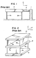
- fine positioning devices As such fine positioning devices, a variety of devices have heretofore been proposed, for example, as shown in a Japanese magazine, "Kikai Sekkei (Machine Designing)", 27(1) , 32-36, January 1983. Of such fine positioning devices, those making use of parallel springs and fine motion actuators are considered to be superb in that inter alia , they do not require cumbersome displacement reducing mechanisms and their structures are simple. Accordingly, a fine positioning device of the above sort will hereinafter be described with reference to Figure 1.
- Figure 1 is a side view of a conventional fine positioning device, in which there are illustrated a support table 1, planar parallel springs 2a,2b fixed in parallel to each other on the support table 1, and a fine motion table 3 supported on the parallel spring 2a,2b and having a high degree of rigidity.
- Designated at numeral 4 is a fine motion actuator mounted between the support table 1 and fine motion table 3.
- the fine motion actuator 4 makes use of a piezoelectric element, electromagnetic solenoid or the like, which is energized to apply a force to the fine motion table 3 along the x-axis of the coordinate system depicted in the figure.
- the parallel springs 2a,2b reflecting their structure, have low rigidity in the direction of the x-axis but high rigidity in the direction of the z-axis and in the direction of the y-axis (namely, in the direction perpendicular to the drawing sheet).
- the fine motion actuator 4 When the fine motion actuator 4 is energized, the fine motion table 3 thus undergoes a displacement practically along the x-axis only and no substantial displacements take place in the other directions.
- FIG. 2 is a perspective view of another conventional fine positioning device which is readily conceivable from the devices disclosed by way of example in the above-mentioned magazine.
- a support plate 6 a pair of planar parallel springs 7a,7b fixed in parallel to each other on the support table 6, a middle table 8 fixed on the parallel springs 7a,7b and having a high degree of rigidity, another pair of parallel springs 9a,9b fixed on the middle table 8 and extending in parallel to each other in a direction perpendicular to the parallel spring 7a,7b, and a fine motion table 10 fixed on the parallel spring 9a,9b and having a high degree of rigidity.
- the parallel spring 7a,7b are arranged along the x-axis, while the parallel springs 9a,9b are disposed along the y-axis.
- This structure corresponds basically to a structure obtained by stacking two structures, each of the same type as the one-axis (displaceable along the x-axis only) structure depicted in Figure 1, one over the other.
- An arrow F x indicates a force to be applied along the x-axis to the fine motion table 10
- an arrow F y designates a force to be applied along the y-axis to the middle table 8.
- Unillustrated actuators which can apply the forces F x ,F y are provided respectively between the support table 6 and fine motion table 10 and between the support table 6 and the middle table 8.
- the parallel springs 9a,9b are deformed. Since the parallel springs 7a,7b have high rigidity against the force F x applied along the x-axis, the fine motion table 10 is allowed to undergo a displacement practically along the x-axis only.
- the parallel springs 7a,7b are deformed and by way of the parallel springs 9a,9b, the fine motion table 10 is displaced practically along the y-axis only.
- the parallel springs 7a,7b,9a,9b are simultaneously deformed.
- the fine motion table 10 is displaced two-dimensionally.
- the device shown in Figure 2 can perform positioning along two axes whereas the device illustrated in Figure 1 is a one-axis positioning device.
- FIG. 3 is a partially cut-away perspective view of a conventional fine positioning device which makes use of fine angular displacements.
- numeral 11 indicates a fixed central portion in the form of a cylindrical column and numerals 11a,11b,11c designate vertical slots formed with an equal interval, along the length of the fixed central portion, in the circumferential wall of the fixed central portion 11.
- a ring-shaped stage 12 provided movably about the fixed central portion 11 and U-like metal members 12a1-12a3, 12b1-12b3,12c1-12c3 secured fixedly on the stage 12 in opposition to the vertical slots 11a,11b,11c respectively.
- Designated at numeral 13 are bimorph cells mounted between the individual vertical slots 11a,11b, 11c and their corresponding U-like metal members 12a1-12c3, while numeral 13A indicates beads fixed on the bimorph cells 13 at locations where the bimorph cells 13 engage their corresponding U-like metal members 12a1-12c3.
- the fixed central portion 11, stage 12 and individual U-like metal members 12a1-12c3 are all rigid.
- FIG. 4 is a perspective view of one of the bimorph cells 12a1-12c3.
- piezoelectric elements 13a,13b and a common electrode 13c provided between the piezoelectric elements 13a,13b.
- the piezoelectric elements 13a,13b are rigidly cemented together with the common electrode 13c interposed therebetween.
- Designated at numerals 13d,13e are surface electrodes applied fixedly to the piezoelectric elements 13a,13b respectively.
- the piezoelectric elements 13a,13b are respectively caused to contract and expand in the directions shown by arrows.
- the bimorph cell 13 is deformed as a whole as shown in the figure. Owing to this property, the bimorph cell 13 can provide a greater degree of displacement compared with a single piezoelectric element.
- the bimorph cells 13 which have the above-described property are fixed at one ends thereof in their corresponding vertical slots 11a,11b,11c but the other ends of the bimorph cells 13 remain as free ends and are kept via their respective beads 13A in contact with the corresponding U-like metal members 12a1-12c3.
- suitable voltages are applied respectively to the bimorph cells 13 so as to cause them to undergo such deformations as shown in Figure 4.
- the stage 12 undergoes an angular displacement about the fixed central portion 11. If a fine motion table is fixedly mounted on the stage 12, it is possible to have the fine motion table to undergo the angular displacement.
- the U-like metal members 12a1-12c3 and their corresponding bimorph cells 13 are kept in mutual contact. Owing to this structural feature, the bimorph cells are mounted while being allowed to undergo free deformations. This structural feature can thus avoid the imminent restraint (interference) of displacements which takes place if the bimorph cells 13 should be fixed to the stage 12.
- the fine positioning devices depicted in Figures 1 and 2 may be used only for one-dimensional and two-dimensional positioning respectively. They can produce neither displacement along the z-axis nor angular displacement about the x-, y- or z-axis. Turning to the fine positioning device shown in Figure 3, it can produce neither displacement along the x-, y- or z-axis nor angular displacement about any one of the other two axes. From these conventional fine positioning devices, it may only be feasible to contemplate a 3-axis fine positioning device, which can produce displacements along both x-axis and y-axis and an angular displacement about the z-axis, by combining the device of Figure 2 and that of Figure 3 together. It is believed to be extremely difficult to construct a 4-axis or larger multi-axis fine positioning device on the basis of such conventional devices.
- the present invention has as its principal objects the solution of the problems of the above-described prior art and at the same time the provision of a fine positioning device which can produce with a simple and small structure displacements along and/or about at least two axes out of displacements along x-, y- and z-axes and those about x-, y- and z-axes.
- the present invention provides in a first aspect thereof a fine positioning device comprising: a central rigid portion; a first set of outwardly-extending portions extending symmetrically along a first axis from the central rigid portion; a second set of outwardly-extending portions extending symmetrically from the central rigid portion along a second axis which is perpendicular to the first axis; a first set of parallel flexible-beam displacement mechanisms provided symmetrically to each other with the first set of outwardly-extending portions respectively to produce translational displacements along the second axis; and a second set of parallel flexible-beam displacement mechanisms provided symmetrically to each other with the second set of outwardly-extending portions respectively to produce translational displacements along the first axis.
- the above fine positioning device can obtain translational displacements along each of two axes which are perpendicular to each other.
- a fine positioning device comprising: a rigid support member; a first set of radial flexible-beam displacement mechanisms provided symmetrically to each other on the support member to produce angular displacements about a first axis; a second set of radial flexible-beam displacement mechanisms provided symmetrically to each other on the support member to produce angular displacements about a second axis which is perpendicular to the first axis; and a third set of radial flexible-beam displacement mechanisms connected to either one of the sets of radial flexible-beam displacement mechanisms to produce angular displacements about a third axis which is perpendicular to both first and second axes.
- the above fine positioning device can obtain angular displacements about each of three axes which are perpendicular to one another.
- a fine positioning device comprising: a first block comprising a central rigid portion, a first set of outwardly-extending portions extending symmetrically along a first axis from the central rigid portion and equipped respectively with first parallel flexible-beam displacement mechanisms to produce in the first set of outwardly-extending portions translational displacements along a second axis which is perpendicular to the first axis, and a second set of outwardly-extending portions extending symmetrically along the second axis from the central rigid portion and equipped respectively with second parallel flexible-beam displacement mechanisms to produce in the second set of outwardly-extending portions translational displacements along the first axis; a second block comprising a central rigid portion and a set of outwardly-extending portions extending symmetrically along the second axis from the central rigid portion, said outwardly-extending portions being equipped respectively with parallel flexible-beam displacement mechanisms adapted to produce translational displacement along a third axis, which is perpendicular to both first
- a fine positioning device comprising: a central rigid portion; a first set of outwardly-extending portions extending symmetrically along a first axis from the central rigid portion; a second set of outwardly-extending portions extending symmetrically from the central rigid portion along a second axis which is perpendicular to the first axis; a set of radial flexible-beam displacement mechanisms provided symmetrically to each other with the first set of outwardly-extending portions respectively and adapted to produce angular displacements about a third axis which is perpendicular to both first and second axes, and a set of parallel flexible-beam displacement mechanisms provided symmetrically to each other with the first set of outwardly-extending portions respectively and adapted to produce translational displacements along the second axis; and a set of parallel flexible-beam displacement mechanisms provided symmetrically to each other with the second set of outwardly-extending portions and adapted to produce translational displacements along the first axis.
- a fine positioning device comprising: a central rigid portion; a first set of outwardly-extending portions extending symmetrically along a first axis from the central rigid portion; a second set of outwardly-extending portions extending symmetrically from the central rigid portion along a second axis which is perpendicular to the first axis; a set of radial flexible-beam displacement mechanisms provided symmetrically to each other with the first set of outwardly-extending portions respectively and adapted to produce angular displacements about a third axis which is perpendicular to both first and second axes, and a set of parallel flexible-beam displacement mechanisms provided symmetrically to each other with the first set of outwardly-extending portions respectively and adapted to produce translational displacements along the second axis; a set of parallel flexible-beam displacement mechanisms provided symmetrically to each other with the second set of outwardly-extending portions and adapted to produce translational displacements along the first axis; and
- a fine positioning device comprising: a rigid support plate; radial flexible-beam displacement mechanisms provided on the support plate and adapted to produce angular displacements about a first axis; and radial flexible-beam displacement mechanisms provided on the support plate and adapted to produce angular displacements about a second axis which is perpendicular to the first axis.
- a fine positioning device comprising: a central rigid portion; a first set of outwardly-extending portions extending symmetrically along a first axis from the central rigid portion; a second set of outwardly-extending portions extending symmetrically from the central rigid portion along a second axis which is perpendicular to the first axis; a set of radial flexible-beam displacement mechanisms provided symmetrically to each other with the first set of outwardly-extending portions respectively and adapted to produce angular displacements about a third axis which is perpendicular to both first and second axes, and a set of parallel flexible-beam displacement mechanisms provided symmetrically to each other with the first set of outwardly-extending portions respectively and adapted to produce translational displacements along the second axis; a set of parallel flexible-beam displacement mechanisms provided symmetrically to each other with the second set of outwardly-extending portions and adapted to produce translational displacements along the first axis, and
- the fine positioning device of this invention is constructed by providing one or more parallel flexible-beam displacement mechanisms and/or radial flexible beam displacement mechanisms in a rigid member.
- the fine positioning device hence has a simple and small overall structure.
- Each parallel flexible-beam displacement mechanism or radial flexible-beam displacement mechanism can be provided with a displacement controller.
- a displacement controller can be provided for the entire fine positioning device. It is therefore possible to obtain a displacement of high accuracy.
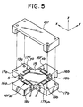
- the outwardly-extending portions 16a,16b,17a, 17b, fixed portions 18a,18b and fine motion table connecting portions 19a,19b are all formed of the same material as the central rigid portion 15 and are worked or machined out together with the central rigid portion 15 from a single block.
- Designated at numerals 16F xa ,16F xb are parallel flexible-beam displacement mechanisms formed in the outwardly-expanding portions 16a,16b respectively.
- the parallel flexible-beam displacement mechanisms 16F xa , 16F xb are formed symmetrically to each other relative to the central rigid portion 15.
- the parallel flexible-beam displacement mechanisms 16F xa ,16F xb cooperate to produce translational displacements along the x-axis.
- Designated at numerals 17F ya ,17F yb are parallel flexible-beam displacement mechanisms formed in the outwardly-expanding portions 17a,17b respectively.
- the parallel flexible-beam displacement mechanisms 17F ya , 17F yb are formed symmetrically to each other relative to the central rigid portion 15.
- the parallel flexible-beam displacement mechanisms 17F ya ,17F yb cooperate to produce translational displacements along the y-axis.
- the structure of the parallel flexible-beam displacement mechanism will be described subsequently.
- the parallel flexible-beam displacement mechanisms 16F xa ,16F xb ,17F ya ,17F yb are formed by formed predetermined through-holes at desired locations in the respective outwardly-extending portions 16a,16b,17a, 17b.
- Letter S indicates strain gauges provided with each parallel flexible-beam displacement mechanism.
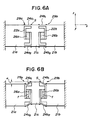
- FIGS. 6A and 6B are side views of a symmetrical parallel flexible-beam displacement mechanism.
- numerals 21a,21b,21c indicate rigid portions while numerals 24a1,24a2 designate parallel flexible beams connected in parallel to each other between the rigid portions 21c,21a.
- the parallel flexible beams 24a1,24a2 are formed by a through hole 22a formed through the rigid portion.
- Designated at numerals 24b1,24b2 designate parallel flexible beams connected in parallel to each other between the rigid portions 21b,21c.
- the parallel flexible beams 24a1,24a2 are formed by a through hole 22b formed through the rigid portion.
- Numerals 26a, 26b indicate piezoelectric actuators, which are fit between tongues extending from the rigid portions into the respective through-holes 22a,22b.
- a parallel flexible-beam displacement mechanism 29a is constructed by the elements located on the left hand relative to the center line of the rigid portion 21c, while another parallel flexible-beam displacement mechanism 29b is by the elements located on the right hand relative to the center line of the rigid portion 21c.
- Letter S indicates strain gauges provided at suitable locations on each parallel flexible beam.
- the parallel flexible-beam 24a1,24a2 thus undergo a bending deformation like the parallel springs 2a,2b depicted in Figure 1, so that the rigid portion 21c is displaced along the z-axis as illustrated in Figure 6B. If the other parallel flexible-beam displacement 29b were not provided, a lateral displacement (a displacement along the x-axis) should take place at the same time in the rigid portion 21c albeit extremely small.
- the magnitude and direction of the lateral displacement are plane-symmetrical with those of the lateral displacement of the parallel flexible-beam displacement mechanism 29a.
- the lateral displacement occurred in the parallel flexible-beam displacement mechanism 29a is a combination of a displacement occurred in the leftward direction along the x-axis as viewed in the drawing and an angular displacement occurred counterclockwise about the y-axis as viewed in the same drawing
- the lateral displacement occurred in the parallel flexible-beam displacement mechanism 29b is a combination of a displacement occurred in the rightward direction along the x-axis as viewed in the drawing and an angular displacement occurred clockwise about the y-axis as viewed in the same drawing.
- the magnitudes of the displacements along the x-axis are equal to each other and those of the angular displacements about the y-axis are also equal to each other.
- the lateral displacements occurred respectively in the parallel flexible-beam displacement mechanisms 29a,28b are canceled each other.
- a slight increase in internal stress is alone caused to occur in each of the parallel flexible beams 24a1,24a2,24b1,24b2 due to a lengthwise elongation thereof by the application of the force f and the rigid portion 21c undergoes a displacement (principal displacement) ⁇ along the z-axis only.
- the parallel flexible beams 24a1,24a2,24b1,24b2 returns to their respective state before their deformation so that the parallel flexible-beam displacement mechanisms 29a,29b return to their respective state shown in Figure 6A and the displacement ⁇ is reduced to 0.
- Accurate positioning can be performed by detecting actual displacements by the respective strain gauges S in the course of the above-described operation and then effecting a feedback control based on the displacements.
- the fine positioning device of the first embodiment can avoid lateral displacements and can obtain translational displacements along two axes in spite of its extremely simple and small construction.
- FIG. 7 is an exploded perspective view of the fine positioning device according to the second embodiment of this invention.
- x, y and z indicate coordinate axes respectively.
- Designated at numeral 35 is a square ring made of a rigid material.
- Numerals 36M ya and 36M yb indicate respectively radial flexible-beam displacement mechanisms arranged symmetrically on the ring 35.
- Each of the radial flexible-beam displacement mechanisms 36M ya ,36M yb produces angular displacements about the y-axis.
- Numerals 36M xa and 36M xb indicate respectively radial flexible-beam displacement mechanisms arranged symmetrically on the ring 35. They individually produces angular displacements about the x-axis.
- the structure of each of the radial flexible-beam displacement mechanisms 36M ya ,36M yb ,36M xa ,36M xb will be described subsequently.
- Numerals 37a,37b indicate one set of rigid portions forming the radial flexible-beam displacement mechanisms 36M ya ,36M yb respectively (the other rigid portion being the ring 35), while numerals 38a,38b indicate one set of rigid portions forming the radial flexible-beam displacement mechanisms 36M xa ,36M xb respectively (the other rigid portion being also the ring 35).
- Designated at numerals 38a ⁇ and 38b ⁇ are attachment portions provided on the upper surfaces of end portions 38a,38b respectively.
- numeral 40 Designated at numeral 40 is a central rigid portion
- numeral 41a indicates an outwardly-extending portion extending out along the y-axis from the central rigid portion 40
- numeral 41b designates another outwardly-extending portion extending out from the central rigid portion 40 in a direction opposite to the former outwardly-extending portion 41a.
- the outwardly-extending portion 41a and the rigid portion 37a of the radial flexible displacement mechanisms 36M ya are connected to each other, whereas the outwardly-extending portion 41b and the rigid portion 37b of the radial flexible displacement mechanisms 36M yb are connected to each other.
- Numerals 41M za ,41M zb indicate radial flexible-beam displacement mechanisms formed in the outwardly-extending portions 41a,41b respectively. They are arranged symmetrically to each other relative to the central rigid portion 40. These radial flexible-beam displacement mechanisms 41M za ,41M zb cooperate to produce angular displacements about the z-axis. These radial flexible-beam displacement mechanisms 41M za , 41M zb and the aforementioned radial flexible-beam displacement mechanisms 36M xa ,36M xb ,36M ya ,36M yb are constructed by forming desired through-holes at predetermined locations. The structure of the radial flexible-beam displacement mechanisms 41M za ,41M zb will also be described subsequently.
- the ring 35, the rigid portions 37a,37b,38a,38b, the individual radial displacement flexible-beam mechanisms formed between the ring and the rigid portions 37a,37b,38a,38b, the central rigid portion 40, and the outwardly-extending portions 41a,41b are all formed as an integral unit from a single piece of high-rigidity material.
- Numeral 43 indicates a fine motion table mounted on attachment portions 38a ⁇ 38b ⁇ of the rigid portions 38a,38b.
- An object to be subjected to fine positioning is fixedly mounted on the fine motion table 43.
- the manner of attachment between the fine motion table 43 and attachment portions 38a ⁇ 38b ⁇ is indicated at one location only by a two-dot chain line in the drawing.
- Numeral 44 indicates a mount made of a rigid material.
- the mount 44 is formed of a recessed portion 44c, land portions 44a,44b provided on both sides of the recessed portion 44c, and attachment portions 44d,44e extending out from lower end portions of the respective land portions 44a,44b.
- the central rigid portion 40 is fit and fixed in the recessed portion 44c. The manner of this fixed fitting is indicated at one location only by a two-dot chain line in the drawing.
- the attachment portions 44d,44e are fixed on the fixing portions (not shown). With the central rigid portion 40 fixed on the recessed portion 44c, a major portion of the mount 44 is received within a space surrounded by the ring 35.
- the radial flexible-beam displacement mechanisms 36M xa ,36M xb , 36M ya ,36M yb are suspended together with the ring 35 from the outwardly-extending portions 41a,41b.
- letter S indicates strain gauges provided with each of the radial flexible-beam displacement mechanisms.
- each radial flexible-beam displacement mechanism is now explained with reference to Figures 8A and 8B, which are side views of the radial flexible-beam displacement mechanism respectively.
- numerals 45a,45b indicate rigid portions located on left-hand and right-hand sides respectively.
- Designated at numerals 46,46 ⁇ are planar radial flexible beams formed between the rigid portions 45a,45b as integral members with the rigid portions 45a,45b and arranged radially about a fixed point O as a center.
- Numeral 47 indicates a through-hole bored to form the radial flexible beams 46,46 ⁇ and rigid portions 45a,45b as an integral unit.
- Numeral 48a indicates a tongue projecting into the through-hole 47 from the rigid portion 45a while numeral 48b designates another tongue projecting into the through-hole 47 from the rigid portion 45b.
- These tongues 48a,48b are overlapped with each other in the vertical direction as viewed in the drawing, with an interval left therebetween.
- Designated at numeral 49 is a piezoelectric actuator fixed between the tongue 48a and tongue 48b. When a circle passing through the piezoelectric actuator 49 is drawn about the point O, the piezoelectric actuator 49 generates a force f (which can be considered as a torque relative to the point O) in a direction tangent to the circle so that a bending deformation is caused to occur in each of the radial flexible beams.
- Numeral 50 indicates a rigid structure on which the rigid portion 45a is supported.
- Letter S indicates strain gauges cemented to the respective radial flexible beams at desired locations. These strain gauges S are provided to detect the degrees of displacements of the radial flexible beams.
- a radial flexible-beam displacement mechanism 52 is constructed by the rigid portions 45a,45b, radial flexible beams 46,46 ⁇ , tongues 48a,48b and piezoelectric actuator 49.
- a line which extends through the point O and is perpendicular to the drawing sheet will hereinafter be considered as a standard axis showing the position and the direction of arrangement of the radial flexible-beam displacement mechanism 52.
- Figure 8B is a side view of the radial flexible-beam displacement mechanism 52, which is illustrated in Figure 8A, after its deformation.
- the tongue 48b is then pushed upwardly along the tangent line by the force generated in the piezoelectric actuator 49.
- the rigid portion 45b is in a state connected to the rigid portion 45a by way of the radial flexible beams 46,46 ⁇ .
- portions of the flexible beams 46,46 ⁇ at which portions the flexible beams 46,46 ⁇ are connected to the rigid portion 45a remain respectively on straight lines L1,L2 extending out radially from the point O but portions of the flexible beams 46,46 ⁇ at which portions the flexible beams 46,46 ⁇ are connected to the rigid portion 45b undergo small displacements so that the latter portions are displaced onto straight lines L 1 ⁇ ,L 2 ⁇ (the straight lines L 1 ⁇ ,L 2 ⁇ also extend out radially from the point O) offset slightly from the corresponding straight lines L1,L2.
- the rigid portion 45b is caused to turn over a small angle ⁇ clockwise as viewed in the drawing. Since the degree of this angular displacement ⁇ is determined by the flexural rigidity of the radial flexible beams 46,46 ⁇ , the angular displacement ⁇ can be controlled with the same accuracy as the force f provided that the force f is controlled precisely.
- each of the radial flexible-beam displacement mechanisms 36M ya ,36M yb shown in Figure 7 is the y-axis while the standard axis of each of the radial flexible-beam displacement mechanisms 36M xa ,36M xb is the x-axis.
- the ring 35 depicted in Figure 7 corresponds to the rigid portion 45b while the rigid portions 37a,37b,38a,38b correspond to the rigid portion 45a.
- the respective standard axes y,x of the radial flexible-beam displacement mechanisms 36M ya ,36M yb ,36M xa ,36M xb shown in Figure 7 may be set to extend on the surface of the fine motion table 43 provided that the opening angle ⁇ between their associated radial flexible beams 46,46 ⁇ is chosen suitably.
- the radial flexible-beam displacement mechanisms 41M za ,41M zb shown in Figure 7 share the rigid portion 45b.
- Two rigid portions, each of which is of the same type as the rigid portion 40, are provided on both sides of the common rigid portion 45b, whereby a symmetrical radial flexible-beam displacement mechanism is formed.
- the rigid portion 45b is fixed in contrast to the structure depicted in Figure 8A.
- the symmetrical radial flexible-beam displacement mechanism will next be described.
- Figures 9A and 9B are side views of the symmetrical radial flexible-beam displacement mechanism, in which numerals 55a,55b,55c indicate rigid portions while numerals 58a1, 58a2, 58b1 and 58b2 designate radial flexible beams.
- the radial flexible beams 58a1, 58a2, 58b1 and 58b2 extend radially along their corresponding two-dot chain lines L1,L2 relative to an axis O which extends through the center of the rigid portion 55c and is perpendicular to the drawing sheet.
- the radial flexible beams 58a1, 58a2, 58b1 and 58b2 therefore connect the corresponding adjacent rigid portions.
- the radial flexible beams 58a1,58a2 are formed by boring a through-hole 56a, while the radial flexible beams 58b1,58b2 are formed by boring a through-hole 56b.
- Designated at numerals 60a,60b are piezoelectric actuators, which are mounted between their corresponding tongues extending into the through-holes 56a,56b from the corresponding rigid portions.
- a radial flexible-beam displacement mechanism 63a is constructed by the elements on the left-hand side of the axis O, while a radial flexible-beam displacement mechanism 63b is constructed by the elements on the right-hand side of the axis O.
- Letter S indicate strain gauges cemented on the radial flexible beams at desired locations. The strain gauges S are provided to detect the degrees of deformations of the radial flexible beams.
- portions of the flexible beams 58a1,58a2,58b1,58b2 at which portions the flexible beams are connected to their corresponding rigid portion 55a,55b as shown in Figure 9B remain respectively on straight lines L1,L2 extending out radially from the point O but portions of the flexible beams at which portions the flexible beams are connected to the rigid portion 55c undergo small displacements so that the latter portions are displaced onto straight lines L 1 ⁇ ,L 2 ⁇ (which are also straight lines extending radially from the point O) offset slightly from the corresponding straight lines L1,L2.
- the rigid portion 55c is caused to turn over a small angle ⁇ clockwise as viewed in the drawing.
- the angular displacement ⁇ can be controlled with the same accuracy as the forces f provided that the forces f are controlled precisely.
- the individual radial flexible beams 58a1,58a2,58b1,58b2 are allowed to return their respective states before their deformations so that the radial flexible-beam displacement mechanism returns to the state depicted in Figure 9A and the angular displacement ⁇ is reduced to 0.
- the strain gauges S are employed to achieve accurate fine positioning.
- the fine motion table 43 undergoes an angular displacement which is a combination of angular displacements of the desired two or more radial flexible-beam displacement mechanisms.
- the crossing point of the x-axis, y-axis and z-axis is located on the surface of the fine motion table. It is however not essential for the crossing point to assume a position on the surface of the fine motion table. The location of the crossing point can therefore be selected at any location as desired.
- the fine positioning device of the second embodiment can obtain angular displacements about three axes in spite of its simple structure. Since the y-axis and x-axis which are standard axes of each radial flexible-beam displacement mechanism are positioned on the fine motion table, the turning center of each angular displacement is also located on the fine motion table so that the angular displacement can be achieved accurately.
- FIG 10 is an exploded perspective view of a fine positioning device according to the third embodiment of this invention.
- This embodiment is a combination of the fine positioning device according to the first embodiment, the fine positioning device according to the second embodiment and a further fine positioning device capable of producing translational displacements along two axes, thereby constructing a 6-axis fine positioning device (translational displacements along the x-, y- and z-axes and angular displacements about the x-, y- and z-axes).
- letter B1 indicates a block constituting the same fine positioning device as that shown in Figure 5
- letter B3 designates another block constituting the same fine positioning device as that depicted in Figure 7.
- elements forming these blocks B1,B3 those similar to their corresponding parts in Figures 5 and 7 are identified by like reference numerals and letters and their description is omitted herein.
- a block B2 is a block constructed of a fine positioning device having the same external shape as the mount 44 shown in Figure 7.
- a central rigid portion 65 made of a material having high rigidity
- an outwardly-extending portion 66a extending out from the central rigid portion 65 along the x-axis
- another outwardly-extending portion 66b extending out from the central rigid portion 65 in a direction opposite to the outwardly-extending portion 66a.
- Designated at numerals 67a,67b are connecting portions extending out respectively from lower edge portions of the outwardly-extending portions 66a,66b.
- the connecting portions 67a,67b are connected to connecting portions 19a,19b of the block B1. This connection is indicated by two-dot chain lines.
- the central rigid portion 65, outwardly-extending portions 66a,66b and connecting portions 67a,67b are worked out as an integral unit from a single block.
- Designated at numerals 66F za ,66F zb are parallel flexible-beam displacement mechanisms constructed in the outwardly-extending portions 66a,66b respectively.
- the parallel flexible-beam displacement mechanisms 66F za ,66F zb are arranged symmetrically to each other relative to the central rigid portion 65. These parallel flexible-beam displacement mechanisms 66F za , 66F zb cooperate with each other to produce translational displacements along the z-axis.
- the parallel flexible-beam displacement mechanisms 66F za ,66F zb are formed by boring predetermined through-holes in the corresponding outwardly-extending portions 66a,66b at desired locations respectively.
- the block B2 is connected to the central rigid portion 40 of the block B3. Namely, the central rigid portion 40 of the block B3 is superposed on the central rigid portion 65 of the block B2 and the block B2 and block B3 are then connected to each other by a suitable means (one of connecting routes is indicated by a double-dot chain line in the drawing). In this state, a major part of the block B2 is received within the space of the block B3. Hence, the radial flexible-beam displacement mechanisms 36M xa ,36M xb ,36M ya ,36M yb are suspended together with the ring 35 from the outwardly-extending portions 41a,41b.
- the fine motion table 43 is connected to the rigid portions not connected to the outwardly-extending portions 41a,41b in the block B3, namely, to the connecting portions 38a ⁇ ,38b ⁇ of the rigid portions 38a,38b (one of these connecting routes is indicated by a double-dot chain line in the drawing).
- the turning axes of the respective radial flexible-beam displacement mechanisms 36M xa ,36M xb ,36M ya ,36M yb ,41M za ,41M zb can be designed to cross perpendicularly at one point on the surface of the fine motion table 43 by choosing the opening angles of the respective flexible beams suitably.
- the fine motion table 43 undergoes an angular displacement about the y-axis in proportion to the voltages applied.
- the fine motion table 43 undergoes a radial displacement about the x-axis.
- the fine motion table 43 undergoes an angular displacement about the z-axis.
- the fine motion table 43 can however be displaced as desired by choosing desired plural displacement mechanisms from the above-described parallel flexible-beam displacement mechanisms and radial flexible-beam displacement mechanisms and then applying desired voltages to the thus-chosen displacement mechanisms.
- the degree of each displacement can be controlled accurately by using strain gauges S.
- the end portions of the outwardly-extending portions extending out along the y-axis in the block B1 are fixed while its connecting portions are provided at the end portions of the outwardly-extending portions extending out along the x-axis.
- the end portions of the outwardly-extending portions extending out along the x-axis may be fixed and the block B2 may be connected to the end portions of the outwardly-extending portions extending out along the y-axis.
- Each of the turning axes is not absolutely required to assume a position on the surface of the fine motion table. The position of each turning axis can be chosen as desired.
- the fine positioning device can obtain translational displacements along three axes and angular displacements about three axes in spite of its simple and small structure. Since all the turning axes cross perpendicularly at one point on the surface of the fine motion table, the turning center of angular displacements is located on the fine motion table so that accurate angular displacement can be effected.
- Figure 11 is an exploded perspective view of the fine positioning device according to the fourth embodiment of this invention.
- This embodiment has a structure which is obtained by adding to the first embodiment a radial flexible-beam displacement mechanism capable of producing angular displacements about two axes and a parallel flexible-beam displacement mechanism capable of producing translational displacements along two axes.
- x, y and z indicate respectively coordinate axes which are perpendicular to one another.
- a central rigid portion 70 there are also shown a central rigid portion 70, an outwardly-extending portion 71a extending out along the y-axis from the central rigid portion 70, an outwardly-extending portion 71b extending out from the central rigid portion 70 in a direction opposite to the outwardly-extending portion 71a, an outwardly-extending portion 72a extending out along the x-axis from the central rigid portion 70, and an outwardly-extending portion 72b extending out from the central rigid portion 70 in a direction opposite to the outwardly-extending portion 72a.
- Numerals 73a,73b designate fixing portions provided at lower edge portions of the outwardly-extending portions 71a,71b respectively.
- Designated at numerals 74a,74b are fine motion table connecting portions provided on upper end portions of the outwardly-extending portions 72a,72b respectively.
- Numeral 75 indicates a fine motion table.
- the outwardly-extending portions 71a,71b,72a,72b, fixing portions 73a,73b and fine motion table connecting portions 74a,74b are all formed of the same material as the central rigid portion 70. They are worked out together with the central rigid portion 70 from a single piece of block.
- Designated at numeral 71M za ,71M zb are respectively radial flexible-beam displacement mechanisms, which are constructed in the outwardly-extending portions 71a,71b respectively.
- the radial flexible-beam displacement mechanisms are constructed symmetrically to each other with respect to the central rigid portion 70 and cooperate with each other to produce angular displacements about an axis extending in the direction of the z-axis.
- Numerals 71F xa ,71F xb indicate respectively parallel flexible-beam displacement mechanisms provided outside the respective radial flexible-beam displacement mechanisms 71M za ,71M zb in the outwardly-extending portions 71a,71b.
- the parallel flexible-beam displacement mechanisms 71F xa , 71F xb are constructed symmetrically to each other relative to the central rigid portion 70 and cooperate with each other to produce translational displacements along the x-axis.
- Designated at numeral 72F ya ,72F yb are respectively parallel flexible-beam displacement mechanisms, which are constructed in the outwardly-extending portions 72a,72b respectively.
- the parallel flexible-beam displacement mechanisms are constructed symmetrically to each other with respect to the central rigid portion 70 and cooperate with each other to produce translational displacements along the y-axis.
- Numerals 72F za ,72F zb indicate respectively parallel flexible-beam displacement mechanisms provided outside the respective parallel flexible-beam displacement mechanisms 72F ya ,72F yb in the outwardly-extending portions 72a,72b.
- the parallel flexible-beam displacement mechanisms 72F za ,72F zb are constructed symmetrically to each other relative to the central rigid portion 70 and cooperate with each other to produce translational displacements along the z-axis.
- the portions where the parallel flexible-beam displacement mechanisms 72F za , 72F zb are constructed are formed in such a way that their upper end portions are taller than the other portions.
- the radial flexible-beam displacement mechanisms 71M za ,71M zb and parallel flexible-beam displacement mechanisms 71F xa ,71F xb ,72F ya ,72F yb ,72F za ,72F zb are constructed by boring predetermined through-holes in the respective outwardly-extending portions 71a,71b,72a,72b at desired locations.
- parallel flexible-beam displacement mechanisms are provided to produce translational displacements along the z-axis.
- the parallel flexible-beam displacement mechanism may be removed depending on the application field.
- the end portions of the outwardly-extending portions extending out along the y-axis are fixed and the fine motion table is provided on the end portions of the outwardly-extending portions extending out along the x-axis.
- the end portions of the outwardly-extending portions extending out along the x-axis may be fixed and the fine motion table may be provided on the end portions of the outwardly-extending portions extending out along the y-axis.
- the portions on which the fine motion table is fixed is constructed taller than the other portions. These portions may however be formed at the same height as the other portions and legs may instead be provided on the side of the fine motion table.
- the fine positioning device can obtain translational displacements along two or three axes and angular displacements about one axis in spite of its extremely simple and small structure.
- Figure 12 is an exploded perspective view of the fine positioning device according to the fifth embodiment of this invention.
- This embodiment has a structure equivalent to a structure which is obtained by omitting from the second embodiment the radial flexible-beam displacement mechanisms capable of producing angular displacements about the z-axis.
- x, y and z indicate respectively coordinate axes.
- Numerals 78M ya ,78M yb indicate respectively radial flexible-beam displacement mechanisms provided symmetrically to each other on a support plate 77.
- Each of the radial flexible-beam displacement mechanisms 78M ya ,78M yb produces angular displacements about the y-axis.
- Designated at numerals 78M xa ,78M xb are radial flexible-beam displacement mechanisms arranged symmetrically on the support plate 77. Each of the radial flexible-beam displacement mechanisms 78M xa ,78M xb produces angular displacements about the x-axis.
- Designated at numerals 79a,79b are one set of rigid portions constructing the radial flexible-beam displacement mechanisms 78M ya , 78M yb (the other rigid portion being the support plate 77), while numerals 80a,80b indicate one set of rigid portions constructing the radial flexible-beam displacement mechanisms 78M xa , 78M xb (the other rigid portion being also the support plate 77).
- numerals 81a,81b indicate L-shaped fixing portions connected fixedly to the rigid portions 80a,80b, while numeral 82 indicates a fine motion table fixed on the rigid portions 79a,79b. An object to be subjected to fine positioning is mounted fixedly on the fine motion table 82.
- the standard axes of the respective radial flexible-beam displacement mechanisms can be designed to extend on the surface of the fine motion table 82 by choosing the opening angles ⁇ of their respective radial flexible beams.
- each of the piezoelectric actuators of the radial flexible-beam displacement mechanisms 78M ya ,78M yb their radial flexible beams are deformed as shown in Figure 8B. Since the support plate 77 is in a state fixed by way of fixing legs 81a,81b and radial flexible-beam displacement mechanisms 78M xa ,78M xb , the radial flexible-beam displacement mechanisms 78M ya ,78M yb produce angular displacements about the y-axis so that the fine motion table 82 undergoes an angular displacement about the y-axis.
- each of the piezoelectric actuators of the radial flexible-beam displacement mechanisms 78M xa ,78M xb When an identical voltage is applied to each of the piezoelectric actuators of the radial flexible-beam displacement mechanisms 78M xa ,78M xb on the other hand, their radial flexible beams are deformed to produce angular displacements about the x-axis. These angular displacements are transmitted to the fine motion table 82 via the support plate 77, radial flexible-beam displacement mechanism 78M ya ,78M yb , whereby the fine motion table 82 undergoes an angular displacement about the x-axis.
- the fine motion table 82 undergoes an angular displacement which is a combination of the angular displacements of the respective radial flexible-beam displacement mechanisms.
- two radial flexible-beam displacement mechanisms are provided symmetrically with respect to each axis. They are however not necessarily limited to the above arrangement.
- One of the two sets of radial flexible-beam displacement mechanisms may be replaced by a single radial flexible-beam displacement mechanism provided centrally. If the single radial flexible-beam displacement mechanism provided centrally is not the radial flexible-beam displacement mechanism that is fixed at its fixing portions, its rigid portion serves as the fine motion table. Further, it is not essential for the y-axis and x-axis that they are present on the surface of the fine motion table. The positions of the y-axis and x-axis can be chosen as desired.
- the fine positioning device of the fifth embodiment can obtain angular displacements about two axes in spite of its simple structure.
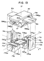
- FIG 13 is an exploded perspective view of the fine positioning device according to the sixth embodiment of this invention.
- the fine positioning device of the sixth embodiment has a structure equivalent to a combination of the fine positioning device of the fourth embodiment and that of the fifth embodiment.
- Elements either identical or equivalent to their corresponding elements shown in Figures 11 and 12 are identified by like reference numerals and letters and their description is omitted herein.
- the connecting portions 74a,74b of the outwardly-extending portions 72a,72b and the L-shaped connecting portions 81a,81b are connected as indicated by two-dot chain lines in the drawing.
- the support plate 77, the radial flexible-beam displacement mechanisms 78M xa ,78M xb ,78M ya ,78M yb supported on the support plate 77 and the fine motion table 82 are in a state suspended over the central rigid portion 70 from the connecting portions 74a,74b,81a,81b.
- angular displacements are transmitted to the fine motion table 82 by way of the central rigid portion 70, parallel flexible-beam displacement mechanisms 72F ya ,72F yb ,72F za ,72F zb , connecting portions 74a,74b,81a,81b, radial flexible-beam displacement mechanisms 78M xa ,78M xb , support plate 77, and radial flexible-beam displacement mechanisms 78M ya ,78M yb , so that the fine motion table 82 undergoes an angular displacement about the z-axis.
- the end portions of the outwardly-extending portions extending out along the x-axis may be fixed and the connecting portions may be provided on the leg portions of the outwardly-extending portions extending out along the y-axis.
- two radial flexible-beam displacement mechanisms are provided symmetrically on the support plate with respect to each axis. They are however not necessarily limited to the above arrangement.
- One of the two sets of radial flexible-beam displacement mechanisms may be replaced by a single radial flexible-beam displacement mechanism provided centrally.
- the single radial flexible-beam displacement mechanism provided centrally is not the radial flexible-beam displacement mechanism that is fixed at its fixing portions, its rigid portion serves as the fine motion table. Further, it is not essential for each turning axis to reside on the surface of the fine motion table. The positions of the turning axes can be chosen as desired.
- the fine positioning device of the sixth embodiment can obtain translational displacements along three axes and angular displacements about three axes in spite of its extremely simple and small structure. Since all the turning axes cross perpendicularly at one point on the surface of the fine motion table, the turning center of each angular displacement is also located on the fine motion table so that an accurate angular displacement can be effected.
- fine positioning devices making use of one or more parallel flexible-beam displacement mechanisms and/or radial flexible-beam displacement mechanisms have been described by way of example. These fine positioning devices can each produce a desired displacement with relatively high accuracy by applying a predetermined voltage to each of their piezoelectric actuators.
Claims (6)
- Vorrichtung zur Feinverstellung, versehen mit:- einem starren Stützteil (81a, 81b; 40, 41a, 41b);- einer starren Stützplatte (77, 35);- einem ersten radialen Flexibelbalkenverschiebungsmechanismus (78Mxa; 36Mya) zum Erzeugen von Winkelverschiebungen um eine erste Achse (x; y), welcher Mechanismus zwischen der Stützplatte (77, 35) und dem starren Stützteil (81a, 81b; 40, 41a, 41b) angeordnet ist;- einem Feinbewegungstisch (82, 43);- einem zweiten radialen Flexibelbalkenverschiebungsmechanismus (78Mya; 36Mxa) zum Erzeugen von Winkelverschiebungen um eine zweite Achse (y; x), welcher Mechanismus zwischen dem Feinbewegungstisch (82, 43) und der Stützplatte (77, 35) angeordnet ist;wobei die erste und die zweite Achse (x, y) sich auf der Oberfläche des Feinbewegungstisches (82, 43) erstrecken,- zwei ersten radialen Flexibelbalkenverschiebungsmechanismen (78Mxa, 78Mxb; 36Mya, 36Myb) mit zusammenfallenden ersten Achsen (x; y), welche Mechanismen je auf einer Seite der zweiten Achse (y; x) angeordnet sind, und- zwei zweiten radialen Flexibelbalkenverschiebungsmechanismen (78Mya, 78Myb; 36Mxa, 36Mxb) mit zusammenfallenden zweiten Achsen (y; x), welche Mechanismen je auf einer Seite der ersten Achse (x; y) angeordnet sind,wobei die genannten zwei ersten und zwei zweiten radialen Flexibelbalkenverschiebungsmechanismen auf derselben Seite der starren Stützplatte (77; 35) angeordnet sind und der starre Stützteil (81a, 81b; 40, 41a, 41b) sich mindestens teilweise zwischen der starren Stützplatte (77; 35) und dem Feinbewegungstisch (82, 43) erstreckt. (Fig. 12, 7, 10, 13)
- Vorrichtung zur Feinverstellung nach Anspruch 1, gekennzeichnet durch zwei dritte radiale Flexibelbalkenverschiebungsmechanismen (41Mza, 41Mzb) zum Erzeugen von Winkelverschiebungen um eine gemeinsame dritte Achse (z), welche Mechanismen im starren Stützteil zwischen zwei starren seitlichen Teilen (41a, 41b) und einem zentralen starren Teil (40) angeordnet sind, wobei die dritte Achse (z) der genannten zwei dritten radialen Verschiebungsmechanismen (41Mza, 41Mzb) sich durch den Schnittpunkt der genannten ersten und zweiten Achsen (x, y) erstreckt, die sich auf der Oberfläche des Feinbewegungstisches (82, 43) erstrecken. (Fig. 7, 10)
- Vorrichtung zur Feinverstellung nach Anspruch 2, gekennzeichnet durch- einen ersten Block (B₁) mit einem zentralen starren Teil (15), einem ersten Satz sich nach außen erstreckender Teile (16a, 16b), die sich symmetrisch entlang der ersten Achse (y) erstrecken und mit zwei ersten parallelen Flexibelbalkenverschiebungsmechanismen (16Fxa, 16Fxb) zum Erzeugen im ersten Satz sich nach außen erstreckender Teile (16a, 16b) von Parallelverschiebungen entlang der zweiten Achse (x) versehen sind, und einem zweiten Satz sich nach außen erstreckender Teile (17a, 17b), die sich symmetrisch entlang der zweiten Achse (x) erstrecken und mit zwei zweiten parallelen Flexibelbalkenverschiebungsmechanismen (17Fya, 17Fyb) zum Erzeugen im zweiten Satz sich nach außen erstreckender Teile (17a, 17b) Parallelverschiebungen entlang der ersten Achse (y) versehen sind;- einen zweiten Block (B₂) mit einem zentralen starren Teil (65), einem dritten Satz sich nach außen erstreckender Teile (66a, 66b), die sich Symmetrisch entlang der zweiten Achse (x) erstrecken und mit zwei dritten parallelen Flexibelbalkenverschiebungsmechanismen (66Fza, 66Fzb) zum Erzeugen im dritten Satz sich nach außen erstreckender Teile (66a, 66b) von Parallelverschiebungen entlang der dritten Achse (z) versehen sind,wobei der zweite Satz sich nach außen erstreckender Teile (17a, 17b) des ersten Blockes (B₁) am dritten Satz sich nach außen erstreckender Teile (66a, 66b) des zweiten Blockes (B₂) befestigt ist und der zentrale starre Teil (65) des zweiten Blockes (B₂) am zentralen starren Teil (40) des starren Stützteiles (40, 41a, 41b) befestigt ist. (Fig. 10)
- Vorrichtung zur Feinverstellung nach Anspruch 1, gekennzeichnet durch- einen zentralen starren Teil (70);- einen ersten Satz sich nach außen erstreckender Teile (71a, 71b), die sich symmetrisch entlang der zweiten Achse (y) erstrecken;- einen zweiten Satz sich nach außen erstreckender Teile (72a, 72b), die sich symmetrisch entlang der ersten Achse (x) erstrecken;- einen ersten Satz zweier parallelen Flexibelbalkenverschiebungsmechanismen (71Fxa, 71Fxb), symmetrisch zueinander versehen mit dem ersten Satz sich nach außen erstreckender Teile (71a, 71b), zum Erzeugen von Parallelverschiebungen entlang der ersten Achse (x);- einen zweiten Satz zweier parallelen Flexibelbalkenverschiebungsmechanismen (72Fya, 72Fyb), symmetrisch zueinander versehen mit dem zweiten Satz sich nach außen erstreckender Teile (72a, 72b), zum Erzeugen von Parallelverschiebungen entlang der zweiten Achse (y), und- einen dritten Satz zweier parallelen Flexibelbalkenverschiebungsmechanismen (72Fza, 72Fzb), symmetrisch zueinander versehen mit dem zweiten Satz sich nach außen erstreckender Teile (72a, 72b), zum Erzeugen von Parallelverschiebungen entlang der dritten Achse (z),wobei der zweite Satz sich nach außen erstreckender Teile (72a, 72b) am starren Stützteil (81a, 81b) befestigt ist. (Fig. 13)
- Vorrichtung zur Feinverstellung nach einem der Ansprüche 1 bis 4, gekennzeichnet durch ein Stellglied (26a, 26b; 49; 60a, 60b), inbesondere ein piezoelektrisches Stellglied, zum Anlegen eines Moments oder einer Kraft, um eine Biegeverformung in einem Flexibelbalkenverschiebungsmechanismus einzuführen.
- Vorrichtung zur Feinverstellung nach Anspruch 5, dadurch gekennzeichnet, daß das Stellglied (26a, 26b; 49; 60a, 60b) ein piezoelektrisches Stellglied ist.
Applications Claiming Priority (18)
| Application Number | Priority Date | Filing Date | Title |
|---|---|---|---|
| JP61210618A JPH071447B2 (ja) | 1986-09-09 | 1986-09-09 | 微細位置決め装置 |
| JP21061686A JPS6366613A (ja) | 1986-09-09 | 1986-09-09 | 微細位置決め装置 |
| JP21061986A JPS6366615A (ja) | 1986-09-09 | 1986-09-09 | 微細位置決め装置 |
| JP210618/86 | 1986-09-09 | ||
| JP210619/86 | 1986-09-09 | ||
| JP210616/86 | 1986-09-09 | ||
| JP26243786A JPH0652489B2 (ja) | 1986-11-04 | 1986-11-04 | 微細位置決め装置の変位制御装置 |
| JP262437/86 | 1986-11-04 | ||
| JP61283063A JPH071450B2 (ja) | 1986-11-29 | 1986-11-29 | 微細位置決め装置 |
| JP283062/86 | 1986-11-29 | ||
| JP61283062A JPH071449B2 (ja) | 1986-11-29 | 1986-11-29 | 微細位置決め装置 |
| JP283063/86 | 1986-11-29 | ||
| JP61283061A JPH071448B2 (ja) | 1986-11-29 | 1986-11-29 | 微細位置決め装置 |
| JP283061/86 | 1986-11-29 | ||
| JP76269/87 | 1987-03-31 | ||
| JP7627087A JPH071454B2 (ja) | 1986-09-09 | 1987-03-31 | 微細位置決め装置の制御装置 |
| JP7626987A JPH071453B2 (ja) | 1986-09-09 | 1987-03-31 | 微細位置決め装置の制御装置 |
| JP76270/87 | 1987-03-31 |
Publications (3)
| Publication Number | Publication Date |
|---|---|
| EP0264147A2 EP0264147A2 (de) | 1988-04-20 |
| EP0264147A3 EP0264147A3 (en) | 1988-10-05 |
| EP0264147B1 true EP0264147B1 (de) | 1994-01-12 |
Family
ID=27577169
Family Applications (1)
| Application Number | Title | Priority Date | Filing Date |
|---|---|---|---|
| EP87201701A Expired - Lifetime EP0264147B1 (de) | 1986-09-09 | 1987-09-08 | Vorrichtung zur Feinverstellung und Vorrichtung zum Steuern dieser Verstellungen |
Country Status (3)
| Country | Link |
|---|---|
| US (4) | US4991309A (de) |
| EP (1) | EP0264147B1 (de) |
| DE (1) | DE3788773T2 (de) |
Cited By (1)
| Publication number | Priority date | Publication date | Assignee | Title |
|---|---|---|---|---|
| DE102007054308B4 (de) * | 2007-11-08 | 2009-09-10 | INSTITUT FüR MIKROTECHNIK MAINZ GMBH | Antriebsvorrichtung für Erodierwerkzeuge |
Families Citing this family (32)
| Publication number | Priority date | Publication date | Assignee | Title |
|---|---|---|---|---|
| DE3909206C1 (de) * | 1989-03-21 | 1990-05-31 | Adalbert Dr.-Ing. 8000 Muenchen De Bandemer | |
| US5187876A (en) * | 1989-08-04 | 1993-02-23 | Hatheway Alson E | Precision motion transducer |
| WO1991001848A1 (en) * | 1989-08-04 | 1991-02-21 | Hatheway Alson E | Precision motion transducer |
| JP2834832B2 (ja) * | 1990-03-15 | 1998-12-14 | 松下電工株式会社 | 姿勢制御装置 |
| US5130523A (en) * | 1991-04-22 | 1992-07-14 | Raleigh Freddie L | Coordinate measuring machine with improved flexure and clamp for fiber optic connection |
| US5351412A (en) * | 1991-06-11 | 1994-10-04 | International Business Machines Corporation | Micro positioning device |
| US5360974A (en) * | 1992-10-20 | 1994-11-01 | International Business Machines Corp. | Dual quad flexure scanner |
| DE4312937A1 (de) * | 1993-04-21 | 1994-10-27 | Mahle Gmbh | Auslenkbare Lagerung einer Bohrstange an der Arbeitsspindel einer Feinbohrmaschine |
| US5862003A (en) * | 1995-06-23 | 1999-01-19 | Saif; Muhammad T. A. | Micromotion amplifier |
| US6347004B1 (en) | 1998-08-31 | 2002-02-12 | Ricoh Company, Ltd. | Optical scanning apparatus and scanning image forming lens |
| US6183097B1 (en) | 1999-01-12 | 2001-02-06 | Cornell Research Foundation Inc. | Motion amplification based sensors |
| DE19962247A1 (de) | 1999-12-22 | 2001-09-20 | Agie Sa | Bewegungsübertragungsvorrichtung |
| JP2003529876A (ja) * | 2000-03-30 | 2003-10-07 | シーゲイト テクノロジー エルエルシー | ディスク・ドライブのためのマイクロアクチュエータ支援シークおよびヒステリシス補正方法および装置 |
| US6513250B2 (en) * | 2000-07-14 | 2003-02-04 | Rensselaer Polytechnic Institute | Micro positioning device with shared actuators |
| US6606444B2 (en) | 2000-09-28 | 2003-08-12 | Murray R. Harman | Positioning device especially for assembling optical components |
| US20050274219A1 (en) * | 2004-06-01 | 2005-12-15 | Molecular Imprints, Inc. | Method and system to control movement of a body for nano-scale manufacturing |
| JP3792675B2 (ja) * | 2003-06-05 | 2006-07-05 | ファナック株式会社 | 微細位置決め装置及び工具補正方法 |
| US6836968B1 (en) * | 2003-06-25 | 2005-01-04 | Itt Manufacturing Enterprises, Inc. | Precision frictionless flexure based linear translation mechanism insensitive to thermal and vibrational environments |
| US20050170128A1 (en) * | 2004-02-04 | 2005-08-04 | Jean Card And Gift Co., Ltd. | Bag-packed three-dimensional decorative sticker |
| KR100568206B1 (ko) * | 2004-02-13 | 2006-04-05 | 삼성전자주식회사 | 스테이지장치 |
| US7116463B2 (en) * | 2004-07-15 | 2006-10-03 | Optron Systems, Inc. | High angular deflection micro-mirror system |
| DE102004054359B4 (de) * | 2004-11-10 | 2015-11-05 | Fraunhofer-Gesellschaft zur Förderung der angewandten Forschung e.V. | Vorrichtung zur Erzeugung einer Torsionsbewegung und Verwendung derselben |
| KR100687717B1 (ko) * | 2004-12-16 | 2007-02-27 | 한국전자통신연구원 | 압전소자를 채용한 마이크로 스테이지 |
| US7107693B2 (en) * | 2005-01-14 | 2006-09-19 | Illinois Institute Of Technology | Apparatus and method for precise angular positioning |
| JP5197101B2 (ja) * | 2008-03-31 | 2013-05-15 | 日本トムソン株式会社 | 可動テーブル装置 |
| CA2812367C (en) * | 2010-10-21 | 2018-02-27 | Thorlabs, Inc. | Parallellism conservation mechanism for nanopositioner |
| US9370865B1 (en) * | 2012-05-23 | 2016-06-21 | Western Digital Technologies, Inc. | Flexure based compliance device for use with an assembly device |
| JP6128400B2 (ja) * | 2012-10-11 | 2017-05-17 | 株式会社クリエイティブテクノロジー | ワーク保持装置及びこれを用いたワークの横ずれ検出方法 |
| CN104016117B (zh) * | 2014-05-28 | 2017-01-18 | 京东方科技集团股份有限公司 | 一种自动调整基板位置的叉板及调整方法 |
| US10284118B2 (en) * | 2015-02-06 | 2019-05-07 | New Scale Technologies, Inc. | Two-axis angular pointing device and methods of use thereof |
| TWI678253B (zh) * | 2019-01-10 | 2019-12-01 | 大銀微系統股份有限公司 | 撓性機構 |
| CN111434969B (zh) * | 2019-01-15 | 2021-10-15 | 大银微系统股份有限公司 | 挠性机构 |
Family Cites Families (16)
| Publication number | Priority date | Publication date | Assignee | Title |
|---|---|---|---|---|
| US3492894A (en) * | 1967-10-02 | 1970-02-03 | Heald Machine Co | Machine tool |
| DE1764325A1 (de) * | 1968-05-17 | 1971-07-01 | Elektromat Veb | Vorrichtung zum Ausrichten und Befestigen von epitaktisch beschichtetem Halbleitermaterial |
| FR2098524A5 (de) * | 1970-07-17 | 1972-03-10 | Thomson Csf | |
| US4019109A (en) * | 1974-05-13 | 1977-04-19 | Hughes Aircraft Company | Alignment system and method with micromovement stage |
| JPS5611515A (en) * | 1979-07-10 | 1981-02-04 | Chiyou Lsi Gijutsu Kenkyu Kumiai | Aligning unit |
| JPS5774601A (en) * | 1980-10-29 | 1982-05-10 | Pentel Kk | Apparatus for fixing finely displacing table |
| US4575942A (en) * | 1982-10-18 | 1986-03-18 | Hitachi, Ltd. | Ultra-precision two-dimensional moving apparatus |
| ATE30960T1 (de) * | 1983-08-09 | 1987-12-15 | Siemens Ag | Justier- oder positioniertisch und verfahren zu dessen herstellung. |
| US4520570A (en) * | 1983-12-30 | 1985-06-04 | International Business Machines Corporation | Piezoelectric x-y-positioner |
| JPS60150950A (ja) * | 1984-01-20 | 1985-08-08 | Hitachi Ltd | 案内装置 |
| US4559717A (en) * | 1984-02-21 | 1985-12-24 | The United States Of America As Represented By The Secretary Of Commerce | Flexure hinge |
| DE3411651C1 (de) * | 1984-03-29 | 1989-04-27 | bso Steuerungstechnik GmbH, 6603 Sulzbach | Regelanordnung fuer den Gleichlauf mehrerer Antriebe |
| JPS60259347A (ja) * | 1984-06-02 | 1985-12-21 | Canon Inc | 圧電型微動変位素子及びこれを使用した微少位置決め方法 |
| GB2185323B (en) * | 1984-10-12 | 1988-01-06 | Vickers Plc | Microscope having an improved stage |
| US4686440A (en) * | 1985-03-11 | 1987-08-11 | Yotaro Hatamura | Fine positioning device |
| US4667415A (en) * | 1985-11-29 | 1987-05-26 | Gca Corporation | Microlithographic reticle positioning system |
-
1987
- 1987-09-08 EP EP87201701A patent/EP0264147B1/de not_active Expired - Lifetime
- 1987-09-08 DE DE3788773T patent/DE3788773T2/de not_active Expired - Fee Related
-
1988
- 1988-09-14 US US07/244,101 patent/US4991309A/en not_active Expired - Lifetime
- 1988-09-14 US US07/244,169 patent/US4920660A/en not_active Expired - Lifetime
- 1988-09-14 US US07/244,102 patent/US5005298A/en not_active Expired - Lifetime
- 1988-09-14 US US07/244,168 patent/US4888878A/en not_active Expired - Lifetime
Cited By (1)
| Publication number | Priority date | Publication date | Assignee | Title |
|---|---|---|---|---|
| DE102007054308B4 (de) * | 2007-11-08 | 2009-09-10 | INSTITUT FüR MIKROTECHNIK MAINZ GMBH | Antriebsvorrichtung für Erodierwerkzeuge |
Also Published As
| Publication number | Publication date |
|---|---|
| DE3788773D1 (de) | 1994-02-24 |
| US4920660A (en) | 1990-05-01 |
| EP0264147A2 (de) | 1988-04-20 |
| US5005298A (en) | 1991-04-09 |
| EP0264147A3 (en) | 1988-10-05 |
| US4991309A (en) | 1991-02-12 |
| US4888878A (en) | 1989-12-26 |
| DE3788773T2 (de) | 1994-08-04 |
Similar Documents
| Publication | Publication Date | Title |
|---|---|---|
| EP0264147B1 (de) | Vorrichtung zur Feinverstellung und Vorrichtung zum Steuern dieser Verstellungen | |
| EP0195479B1 (de) | Vorrichtung für Feinverstellung | |
| US20040138766A1 (en) | Ultra-precision positioning system | |
| JPH0555263B2 (de) | ||
| JPH07109566B2 (ja) | 微細位置決め装置 | |
| JP2614662B2 (ja) | 微動機構 | |
| JPS62174811A (ja) | 微細位置決め装置 | |
| JPS6366615A (ja) | 微細位置決め装置 | |
| JP3255707B2 (ja) | 微細位置決め装置 | |
| JPH03115892A (ja) | 微動機構 | |
| CN109949856B (zh) | 一种基于柔性铰链的模块化六自由度精密微动机构 | |
| JPH07104723B2 (ja) | 微細位置決め装置 | |
| JPS63137306A (ja) | 微細位置決め装置 | |
| JPS6366613A (ja) | 微細位置決め装置 | |
| EP1549458B1 (de) | Vorrichtung zur zweidimensionalen verschiebung | |
| JPH0716840B2 (ja) | 微動機構 | |
| JPH071450B2 (ja) | 微細位置決め装置 | |
| JPS62214413A (ja) | 微細位置決め装置 | |
| JPH07136888A (ja) | 精密位置決め装置の変位拡大機構 | |
| JPS62214412A (ja) | 微細位置決め装置 | |
| JPS62187912A (ja) | 微細位置決め装置 | |
| JPH071452B2 (ja) | 微細位置決め装置 | |
| JPH04238506A (ja) | 微動機構 | |
| JPH0659734A (ja) | 微細位置決め装置 | |
| JPS62214415A (ja) | 微細位置決め装置 |
Legal Events
| Date | Code | Title | Description |
|---|---|---|---|
| PUAI | Public reference made under article 153(3) epc to a published international application that has entered the european phase |
Free format text: ORIGINAL CODE: 0009012 |
|
| AK | Designated contracting states |
Kind code of ref document: A2 Designated state(s): DE FR GB NL |
|
| PUAL | Search report despatched |
Free format text: ORIGINAL CODE: 0009013 |
|
| AK | Designated contracting states |
Kind code of ref document: A3 Designated state(s): DE FR GB NL |
|
| 17P | Request for examination filed |
Effective date: 19890404 |
|
| 17Q | First examination report despatched |
Effective date: 19900824 |
|
| GRAA | (expected) grant |
Free format text: ORIGINAL CODE: 0009210 |
|
| AK | Designated contracting states |
Kind code of ref document: B1 Designated state(s): DE FR GB NL |
|
| REF | Corresponds to: |
Ref document number: 3788773 Country of ref document: DE Date of ref document: 19940224 |
|
| ET | Fr: translation filed | ||
| PGFP | Annual fee paid to national office [announced via postgrant information from national office to epo] |
Ref country code: GB Payment date: 19940825 Year of fee payment: 8 |
|
| PGFP | Annual fee paid to national office [announced via postgrant information from national office to epo] |
Ref country code: FR Payment date: 19940929 Year of fee payment: 8 |
|
| PGFP | Annual fee paid to national office [announced via postgrant information from national office to epo] |
Ref country code: NL Payment date: 19940930 Year of fee payment: 8 |
|
| PGFP | Annual fee paid to national office [announced via postgrant information from national office to epo] |
Ref country code: DE Payment date: 19941027 Year of fee payment: 8 |
|
| PLBE | No opposition filed within time limit |
Free format text: ORIGINAL CODE: 0009261 |
|
| STAA | Information on the status of an ep patent application or granted ep patent |
Free format text: STATUS: NO OPPOSITION FILED WITHIN TIME LIMIT |
|
| 26N | No opposition filed | ||
| PG25 | Lapsed in a contracting state [announced via postgrant information from national office to epo] |
Ref country code: GB Effective date: 19950908 |
|
| PG25 | Lapsed in a contracting state [announced via postgrant information from national office to epo] |
Ref country code: NL Effective date: 19960401 |
|
| GBPC | Gb: european patent ceased through non-payment of renewal fee |
Effective date: 19950908 |
|
| PG25 | Lapsed in a contracting state [announced via postgrant information from national office to epo] |
Ref country code: FR Effective date: 19960531 |
|
| PG25 | Lapsed in a contracting state [announced via postgrant information from national office to epo] |
Ref country code: DE Effective date: 19960601 |
|
| NLV4 | Nl: lapsed or anulled due to non-payment of the annual fee |
Effective date: 19960401 |
|
| REG | Reference to a national code |
Ref country code: FR Ref legal event code: ST |