EP0264147A2 - Fine positioning device and displacement controller therefor - Google Patents
Fine positioning device and displacement controller therefor Download PDFInfo
- Publication number
- EP0264147A2 EP0264147A2 EP87201701A EP87201701A EP0264147A2 EP 0264147 A2 EP0264147 A2 EP 0264147A2 EP 87201701 A EP87201701 A EP 87201701A EP 87201701 A EP87201701 A EP 87201701A EP 0264147 A2 EP0264147 A2 EP 0264147A2
- Authority
- EP
- European Patent Office
- Prior art keywords
- displacement
- axis
- flexible
- positioning device
- outwardly
- Prior art date
- Legal status (The legal status is an assumption and is not a legal conclusion. Google has not performed a legal analysis and makes no representation as to the accuracy of the status listed.)
- Granted
Links
Images







Classifications
-
- B—PERFORMING OPERATIONS; TRANSPORTING
- B23—MACHINE TOOLS; METAL-WORKING NOT OTHERWISE PROVIDED FOR
- B23Q—DETAILS, COMPONENTS, OR ACCESSORIES FOR MACHINE TOOLS, e.g. ARRANGEMENTS FOR COPYING OR CONTROLLING; MACHINE TOOLS IN GENERAL CHARACTERISED BY THE CONSTRUCTION OF PARTICULAR DETAILS OR COMPONENTS; COMBINATIONS OR ASSOCIATIONS OF METAL-WORKING MACHINES, NOT DIRECTED TO A PARTICULAR RESULT
- B23Q1/00—Members which are comprised in the general build-up of a form of machine, particularly relatively large fixed members
- B23Q1/25—Movable or adjustable work or tool supports
- B23Q1/26—Movable or adjustable work or tool supports characterised by constructional features relating to the co-operation of relatively movable members; Means for preventing relative movement of such members
- B23Q1/34—Relative movement obtained by use of deformable elements, e.g. piezoelectric, magnetostrictive, elastic or thermally-dilatable elements
- B23Q1/36—Springs
-
- B—PERFORMING OPERATIONS; TRANSPORTING
- B23—MACHINE TOOLS; METAL-WORKING NOT OTHERWISE PROVIDED FOR
- B23Q—DETAILS, COMPONENTS, OR ACCESSORIES FOR MACHINE TOOLS, e.g. ARRANGEMENTS FOR COPYING OR CONTROLLING; MACHINE TOOLS IN GENERAL CHARACTERISED BY THE CONSTRUCTION OF PARTICULAR DETAILS OR COMPONENTS; COMBINATIONS OR ASSOCIATIONS OF METAL-WORKING MACHINES, NOT DIRECTED TO A PARTICULAR RESULT
- B23Q15/00—Automatic control or regulation of feed movement, cutting velocity or position of tool or work
- B23Q15/20—Automatic control or regulation of feed movement, cutting velocity or position of tool or work before or after the tool acts upon the workpiece
- B23Q15/22—Control or regulation of position of tool or workpiece
- B23Q15/24—Control or regulation of position of tool or workpiece of linear position
-
- G—PHYSICS
- G05—CONTROLLING; REGULATING
- G05B—CONTROL OR REGULATING SYSTEMS IN GENERAL; FUNCTIONAL ELEMENTS OF SUCH SYSTEMS; MONITORING OR TESTING ARRANGEMENTS FOR SUCH SYSTEMS OR ELEMENTS
- G05B19/00—Program-control systems
- G05B19/02—Program-control systems electric
- G05B19/18—Numerical control [NC], i.e. automatically operating machines, in particular machine tools, e.g. in a manufacturing environment, so as to execute positioning, movement or co-ordinated operations by means of program data in numerical form
- G05B19/19—Numerical control [NC], i.e. automatically operating machines, in particular machine tools, e.g. in a manufacturing environment, so as to execute positioning, movement or co-ordinated operations by means of program data in numerical form characterised by positioning or contouring control systems, e.g. to control position from one programmed point to another or to control movement along a programmed continuous path
- G05B19/21—Numerical control [NC], i.e. automatically operating machines, in particular machine tools, e.g. in a manufacturing environment, so as to execute positioning, movement or co-ordinated operations by means of program data in numerical form characterised by positioning or contouring control systems, e.g. to control position from one programmed point to another or to control movement along a programmed continuous path using an incremental digital measuring device
- G05B19/23—Numerical control [NC], i.e. automatically operating machines, in particular machine tools, e.g. in a manufacturing environment, so as to execute positioning, movement or co-ordinated operations by means of program data in numerical form characterised by positioning or contouring control systems, e.g. to control position from one programmed point to another or to control movement along a programmed continuous path using an incremental digital measuring device for point-to-point control
-
- H—ELECTRICITY
- H02—GENERATION; CONVERSION OR DISTRIBUTION OF ELECTRIC POWER
- H02N—ELECTRIC MACHINES NOT OTHERWISE PROVIDED FOR
- H02N2/00—Electric machines in general using piezoelectric effect, electrostriction or magnetostriction
- H02N2/0095—Electric machines in general using piezoelectric effect, electrostriction or magnetostriction producing combined linear and rotary motion, e.g. multi-direction positioners
-
- H—ELECTRICITY
- H02—GENERATION; CONVERSION OR DISTRIBUTION OF ELECTRIC POWER
- H02N—ELECTRIC MACHINES NOT OTHERWISE PROVIDED FOR
- H02N2/00—Electric machines in general using piezoelectric effect, electrostriction or magnetostriction
- H02N2/02—Electric machines in general using piezoelectric effect, electrostriction or magnetostriction producing linear motion, e.g. actuators; Linear positioners ; Linear motors
- H02N2/028—Electric machines in general using piezoelectric effect, electrostriction or magnetostriction producing linear motion, e.g. actuators; Linear positioners ; Linear motors along multiple or arbitrary translation directions, e.g. XYZ stages
-
- H—ELECTRICITY
- H02—GENERATION; CONVERSION OR DISTRIBUTION OF ELECTRIC POWER
- H02N—ELECTRIC MACHINES NOT OTHERWISE PROVIDED FOR
- H02N2/00—Electric machines in general using piezoelectric effect, electrostriction or magnetostriction
- H02N2/02—Electric machines in general using piezoelectric effect, electrostriction or magnetostriction producing linear motion, e.g. actuators; Linear positioners ; Linear motors
- H02N2/06—Drive circuits; Control arrangements or methods
- H02N2/062—Small signal circuits; Means for controlling position or derived quantities, e.g. for removing hysteresis
-
- H—ELECTRICITY
- H02—GENERATION; CONVERSION OR DISTRIBUTION OF ELECTRIC POWER
- H02N—ELECTRIC MACHINES NOT OTHERWISE PROVIDED FOR
- H02N2/00—Electric machines in general using piezoelectric effect, electrostriction or magnetostriction
- H02N2/10—Electric machines in general using piezoelectric effect, electrostriction or magnetostriction producing rotary motion, e.g. rotary motors
- H02N2/108—Electric machines in general using piezoelectric effect, electrostriction or magnetostriction producing rotary motion, e.g. rotary motors around multiple axes of rotation, e.g. spherical rotor motors
-
- B—PERFORMING OPERATIONS; TRANSPORTING
- B82—NANOTECHNOLOGY
- B82Y—SPECIFIC USES OR APPLICATIONS OF NANOSTRUCTURES; MEASUREMENT OR ANALYSIS OF NANOSTRUCTURES; MANUFACTURE OR TREATMENT OF NANOSTRUCTURES
- B82Y35/00—Methods or apparatus for measurement or analysis of nanostructures
-
- G—PHYSICS
- G05—CONTROLLING; REGULATING
- G05B—CONTROL OR REGULATING SYSTEMS IN GENERAL; FUNCTIONAL ELEMENTS OF SUCH SYSTEMS; MONITORING OR TESTING ARRANGEMENTS FOR SUCH SYSTEMS OR ELEMENTS
- G05B2219/00—Program-control systems
- G05B2219/30—Nc systems
- G05B2219/41—Servomotor, servo controller till figures
- G05B2219/41133—Compensation non linear transfer function
-
- G—PHYSICS
- G05—CONTROLLING; REGULATING
- G05B—CONTROL OR REGULATING SYSTEMS IN GENERAL; FUNCTIONAL ELEMENTS OF SUCH SYSTEMS; MONITORING OR TESTING ARRANGEMENTS FOR SUCH SYSTEMS OR ELEMENTS
- G05B2219/00—Program-control systems
- G05B2219/30—Nc systems
- G05B2219/41—Servomotor, servo controller till figures
- G05B2219/41352—Alternative clamping dilation of piezo, caterpillar motion, inchworm
Definitions
- This invention relates to a fine positioning device suitable for use in an apparatus which requires fine adjustment on the order of micrometers, such as semiconductor fabrication apparatus or electron microscope, and also to a displacement controller for such a fine positioning device.
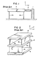
- Figure 1 is a side view of a conventional fine positioning device, in which there are illustrated a support table 1, planar parallel springs 2a,2b fixed in parallel to each other on the support table 1, and a fine motion table 3 supported on the parallel spring 2a,2b and having a high degree of rigidity.
- Designated at numeral 4 is a fine motion actuator mounted between the support table 1 and fine motion table 3.
- the fine motion actuator 4 makes use of a piezoelectric element, electromagnetic solenoid or the like, which is energized to apply a force to the fine motion table 3 along the x-axis of the coordinate system depicted in the figure.
- the parallel springs 2a,2b reflecting their structure, have low rigidity in the direction of the x-axis but high rigidity in the direction of the z-axis and in the direction of the y-axis (namely, in the direction perpendicular to the drawing sheet).
- the fine motion actuator 4 When the fine motion actuator 4 is energized, the fine motion table 3 thus undergoes a displacement practically along the x-axis only and no substantial displacements take place in the other directions.
- FIG. 2 is a perspective view of another conventional fine positioning device which is readily conceivable from the devices disclosed by way of example in the above-mentioned magazine.
- a support plate 6 a pair of planar parallel springs 7a,7b fixed in parallel to each other on the support table 6, a middle table 8 fixed on the parallel springs 7a,7b and having a high degree of rigidity, another pair of parallel springs 9a,9b fixed on the middle table 8 and extending in parallel to each other in a direction perpendicular to the parallel spring 7a,7b, and a fine motion table 10 fixed on the parallel spring 9a,9b and having a high degree of rigidity.
- the parallel spring 7a,7b are arranged along the x-axis, while the parallel springs 9a,9b are disposed along the y-axis.
- This structure corresponds basically to a structure obtained by stacking two structures, each of the same type as the one-axis (displaceable along the x-axis only) structure depicted in Figure 1, one over the other.
- An arrow F x indicates a force to be applied along the x-axis to the fine motion table 10
- an arrow F y designates a force to be applied along the y-axis to the middle table 8.
- Unillustrated actuators which can apply the forces F x ,F y are provided respectively between the support table 6 and fine motion table 10 and between the support table 6 and the middle table 8.
- the parallel springs 9a,9b are deformed. Since the parallel springs 7a,7b have high rigidity against the force F x applied along the x-axis, the fine motion table 10 is allowed to undergo a displacement practically along the x-axis only.
- the parallel springs 7a,7b are deformed and by way of the parallel springs 9a,9b, the fine motion table 10 is displaced practically along the y-axis only.
- the parallel springs 7a,7b,9a,9b are simultaneously deformed.
- the fine motion table 10 is displaced two-dimensionally.
- the device shown in Figure 2 can perform positioning along two axes whereas the device illustrated in Figure 1 is a one-axis positioning device.
- FIG. 3 is a partially cut-away perspective view of a conventional fine positioning device which makes use of fine angular displacements.
- numeral 11 indicates a fixed central portion in the form of a cylindrical column and numerals 11a,11b,11c designate vertical slots formed with an equal interval, along the length of the fixed central portion, in the circumferential wall of the fixed central portion 11.
- a ring-shaped stage 12 provided movably about the fixed central portion 11 and U-like metal members 12a1-12a3, 12b1-12b3,12c1-12c3 secured fixedly on the stage 12 in opposition to the vertical slots 11a,11b,11c respectively.
- Designated at numeral 13 are bimorph cells mounted between the individual vertical slots 11a,11b, 11c and their corresponding U-like metal members 12a1-12c3, while numeral 13A indicates beads fixed on the bimorph cells 13 at locations where the bimorph cells 13 engage their corresponding U-like metal members 12a1-12c3.
- the fixed central portion 11, stage 12 and individual U-like metal members 12a1-12c3 are all rigid.
- FIG. 4 is a perspective view of one of the bimorph cells 12a1-12c3.
- piezoelectric elements 13a,13b and a common electrode 13c provided between the piezoelectric elements 13a,13b.
- the piezoelectric elements 13a,13b are rigidly cemented together with the common electrode 13c interposed therebetween.
- Designated at numerals 13d,13e are surface electrodes applied fixedly to the piezoelectric elements 13a,13b respectively.
- the piezoelectric elements 13a,13b are respectively caused to contract and expand in the directions shown by arrows.
- the bimorph cell 13 is deformed as a whole as shown in the figure. Owing to this property, the bimorph cell 13 can provide a greater degree of displacement compared with a single piezoelectric element.
- the bimorph cells 13 which have the above-described property are fixed at one ends thereof in their corresponding vertical slots 11a,11b,11c but the other ends of the bimorph cells 13 remain as free ends and are kept via their respective beads 13A in contact with the corresponding U-like metal members 12a1-12c3.
- suitable voltages are applied respectively to the bimorph cells 13 so as to cause them to undergo such deformations as shown in Figure 4.
- the stage 12 undergoes an angular displacement about the fixed central portion 11. If a fine motion table is fixedly mounted on the stage 12, it is possible to have the fine motion table to undergo the angular displacement.
- the U-like metal members 12a1-12c3 and their corresponding bimorph cells 13 are kept in mutual contact. Owing to this structural feature, the bimorph cells are mounted while being allowed to undergo free deformations. This structural feature can thus avoid the imminent restraint (interference) of displacements which takes place if the bimorph cells 13 should be fixed to the stage 12.
- the fine positioning devices depicted in Figures 1 and 2 may be used only for one-dimensional and two-dimensional positioning respectively. They can produce neither displacement along the z-axis nor angular displacement about the x-, y- or z-axis. Turning to the fine positioning device shown in Figure 3, it can produce neither displacement along the x-, y- or z-axis nor angular displacement about any one of the other two axes. From these conventional fine positioning devices, it may only be feasible to contemplate a 3-axis fine positioning device, which can produce displacements along both x-axis and y-axis and an angular displacement about the z-axis, by combining the device of Figure 2 and that of Figure 3 together. It is believed to be extremely difficult to construct a 4-axis or larger multi-axis fine positioning device on the basis of such conventional devices.
- the present invention has as its principal objects the solution of the problems of the above-described prior art and at the same time the provision of a fine positioning device which can produce with a simple and small structure displacements along and/or about at least two axes out of displacements along x-, y- and z-axes and those about x-, y- and z-axes, and also the provision of a displacement controller for controlling precisely each displacement of the fine positioning device.
- the present invention provides in a first aspect thereof a fine positioning device comprising: a central rigid portion; a first set of outwardly-extending portions extending symmetrically along a first axis from the central rigid portion; a second set of outwardly-extending portions extending symmetrically from the central rigid portion along a second axis which is perpendicular to the first axis; a first set of parallel flexible-beam displacement mechanisms provided symmetrically to each other with the first set of outwardly-extending portions respectively to produce translational displacements along the second axis; and a second set of parallel flexible-beam displacement mechanisms provided symmetrically to each other with the second set of outwardly-extending portions respectively to produce translational displacements along the first axis.
- the above fine positioning device can obtain translational displacements along each of two axes which are perpendicular to each other.
- a fine positioning device comprising: a rigid support member; a first set of radial flexible-beam displacement mechanisms provided symmetrically to each other on the support member to produce angular displacements about a first axis; a second set of radial flexible-beam displacement mechanisms provided symmetrically to each other on the support member to produce angular displacements about a second axis which is perpendicular to the first axis; and a third set of radial flexible-beam displacement mechanisms connected to either one of the sets of radial flexible-beam displacement mechanisms to produce angular displacements about a third axis which is perpendicular to both first and second axes.
- the above fine positioning device can obtain angular displacements about each of three axes which are perpendicular to one another.
- a fine positioning device comprising: a first block comprising a central rigid portion, a first set of outwardly-extending portions extending symmetrically along a first axis from the central rigid portion and equipped respectively with first parallel flexible-beam displacement mechanisms to produce in the first set of outwardly-extending portions translational displacements along a second axis which is perpendicular to the first axis, and a second set of outwardly-extending portions extending symmetrically along the second axis from the central rigid portion and equipped respectively with second parallel flexible-beam displacement mechanisms to produce in the second set of outwardly-extending portions translational displacements along the first axis; a second block comprising a central rigid portion and a set of outwardly-extending portions extending symmetrically along the second axis from the central rigid portion, said outwardly-extending portions being equipped respectively with parallel flexible-beam displacement mechanisms adapted to produce translational displacement along a third axis, which is perpendicular to both first
- a fine positioning device comprising: a central rigid portion; a first set of outwardly-extending portions extending symmetrically along a first axis from the central rigid portion; a second set of outwardly-extending portions extending symmetrically from the central rigid portion along a second axis which is perpendicular to the first axis; a set of radial flexible-beam displacement mechanisms provided symmetrically to each other with the first set of outwardly-extending portions respectively and adapted to produce angular displacements about a third axis which is perpendicular to both first and second axes, and a set of parallel flexible-beam displacement mechanisms provided symmetrically to each other with the first set of outwardly-extending portions respectively and adapted to produce translational displacements along the second axis; and a set of parallel flexible-beam displacement mechanisms provided symmetrically to each other with the second set of outwardly-extending portions and adapted to produce translational displacements along the first axis.
- a fine positioning device comprising: a central rigid portion; a first set of outwardly-extending portions extending symmetrically along a first axis from the central rigid portion; a second set of outwardly-extending portions extending symmetrically from the central rigid portion along a second axis which is perpendicular to the first axis; a set of radial flexible-beam displacement mechanisms provided symmetrically to each other with the first set of outwardly-extending portions respectively and adapted to produce angular displacements about a third axis which is perpendicular to both first and second axes, and a set of parallel flexible-beam displacement mechanisms provided symmetrically to each other with the first set of outwardly-extending portions respectively and adapted to produce translational displacements along the second axis; a set of parallel flexible-beam displacement mechanisms provided symmetrically to each other with the second set of outwardly-extending portions and adapted to produce translational displacements along the first axis; and
- a fine positioning device comprising: a rigid support plate; radial flexible-beam displacement mechanisms provided on the support plate and adapted to produce angular displacements about a first axis; and radial flexible-beam displacement mechanisms provided on the support plate and adapted to produce angular displacements about a second axis which is perpendicular to the first axis.
- a fine positioning device comprising: a central rigid portion; a first set of outwardly-extending portions extending symmetrically along a first axis from the central rigid portion; a second set of outwardly-extending portions extending symmetrically from the central rigid portion along a second axis which is perpendicular to the first axis; a set of radial flexible-beam displacement mechanisms provided symmetrically to each other with the first set of outwardly-extending portions respectively and adapted to produce angular displacements about a third axis which is perpendicular to both first and second axes, and a set of parallel flexible-beam displacement mechanisms provided symmetrically to each other with the first set of outwardly-extending portions respectively and adapted to produce translational displacements along the second axis; a set of parallel flexible-beam displacement mechanisms provided symmetrically to each other with the second set of outwardly-extending portions and adapted to produce translational displacements along the first axis, and
- a displacement controller for a fine positioning device constructed of planar structural units connected symmetrically and equipped individually with planar flexible beams arranged in an opposing relation between two rigid members and actuators for applying forces between the rigid members, which comprises: displacement detection means arranged at predetermined points on the respective planar structural units; displacement setting means for setting a target displacement for the fine positioning device and outputting values corresponding to displacements of the respective planar structural units corresponding to the target displacement; and control means for controlling voltages to be applied to the respective actuators so that values obtained by the displacement detection means and representing the displacements of the respective planar structural units are coincided with the values output from the displacement setting means and relating to the corresponding displacements.
- the displacement controller can equalize the displacement of each planar structural unit in the symmetrical parallel flexible-beam displacement mechanism or the radial flexible-beam displacement mechanism.
- the displacement of the fine positioning device can be effected precisely by using the above controller for each of the symmetrical parallel flexible-beam displacement mechanism and radial flexible-beam displacement mechanism in the above fine positioning device.
- a controller for a fine positioning device constructed of planar structural units connected symmetrically and equipped individually with planar flexible beams arranged in an opposing relation between two rigid members and actuators for applying forces between the rigid members, which comprises: displacement detection means arranged at predetermined points on the respective planar structural units displacement setting means for setting a target displacement for the fine positioning device and outputting a value corresponding to the target displacement; means for determining, by the displacement detection means a first degree of displacement based on a desired displacement form and a second degree of displacement based on a displacement form other than the desired displacement form; and control means for controlling voltages to be applied to the respective actuator in such a way that the first degree of displacement is coincided with the value output from the displacement setting means and the detection value of the second degree of displacement is controlled at "0".
- the above controller can eliminate angular displacements in the parallel flexible-beam displacement mechanism or translational displacements in the radial flexible-beam displacement mechanism.
- the displacement of the above fine positioning device can be effected precisely by using the above controller for each of the symmetrical parallel flexible-beam displacement mechanism and radial flexible-beam displacement mechanism in the above fine positioning device.
- a displacement controller for a fine positioning device constructed by combining a plurality of fine motion units which are individually equipped with planer flexible beams arranged in an opposing relation between two rigid members and an actuator for applying a force between the rigid members so as to produce a relative displacement corresponding to a drive voltage of the actuator between the rigid members, which comprises: a target displacement setting unit for outputting a target displacement for each predetermined point on the fine positioning device; and a characteristic compensation computing unit having characteristics opposite to a characteristic matrix, which represents the relation between the drive voltage applied to each fine motion unit and the resulting displacement at the predetermined point, and adapted to compute a drive voltage for each fine motion unit in accordance with the opposite characteristics.
- the above displacement controller can avoid interference between the parallel flexible-beam displacement mechanism and radial flexible-beam displacement mechanism in the above fine positioning device.
- the fine positioning device of this invention is constructed by providing one or more parallel flexible-beam displacement mechanisms and/or radial flexible beam displacement mechanisms in a rigid member.
- the fine positioning device hence has a simple and small overall structure.
- Each parallel flexible-beam displacement mechanism or radial flexible-beam displacement mechanism can be provided with a displacement controller.
- a displacement controller can be provided for the entire fine positioning device. It is therefore possible to obtain a displacement of high accuracy.
- Figure 5 is an exploded perspective view of a fine positioning device according to the first embodiment of this invention, in which there are shown coordinate axes x, y and z which are perpendicular to one another, a central rigid portion 15, an outwardly-extending portion 16a extending out along the y-axis from the central rigid portion 15, another outwardly-extending portion 16a extending out along the y-axis from the central rigid portion 15, another outwardly-extending portion 16b extending out from the central rigid portion 15 in a direction opposite to the outwardly-extending portion 16a, a further outwardly-extending portion 17a extending out along the x-axis from the central rigid portion 15, and a still further outwardly-extending portion 17b extending out from the central rigid portion 15 in a direction opposite to the outwardly-extending portion 17a.
- the outwardly-extending portions 16a,16b,17a, 17b, fixed portions 18a,18b and fine motion table connecting portions 19a,19b are all formed of the same material as the central rigid portion 15 and are worked or machined out together with the central rigid portion 15 from a single block.
- Designated at numerals 16F xa ,16F xb are parallel flexible-beam displacement mechanisms formed in the outwardly-expanding portions 16a,16b respectively.
- the parallel flexible-beam displacement mechanisms 16F xa , 16F xb are formed symmetrically to each other relative to the central rigid portion 15.
- the parallel flexible-beam displacement mechanisms 16F xa 16F xb cooperate to produce translational displacements along the x-axis.
- Designated at numerals 17F ya ,17F yb are parallel flexible-beam displacement mechanisms formed in the outwardly-expanding portions 17a,17b respectively.
- the parallel flexible-beam displacement mechanisms 17F ya , 17F yb are formed symmetrically to each other relative to the central rigid portion 15.
- the parallel flexible-beam displacement mechanisms 17F ya ,17F yb cooperate to produce translational displacements along the y-axis.
- the structure of the parallel flexible-beam displacement mechanism will be described subsequently.
- the parallel flexible-beam displacement mechanisms 16F xa ,16F xb ,17F ya ,17F yb are formed by formed predetermined through-holes at desired locations in the respective outwardly-extending portions 16a,16b,17a, 17b.
- Letter S indicates strain gauges provided with each parallel flexible-beam displacement mechanism.
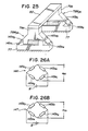
- FIGS. 6A and 6B are side views of a symmetrical parallel flexible-beam displacement mechanism.
- numerals 21a,21b,21c indicate rigid portions while numerals 24a1,24a2 designate parallel flexible beams connected in parallel to each other between the rigid portions 21c,21a.
- the parallel flexible beams 24a1,24a2 are formed by a through hole 22a formed through the rigid portion.
- Designated at numerals 24b1,24b2 designate parallel flexible beams connected in parallel to each other between the rigid portions 21b,21c.
- the parallel flexible beams 24a1,24a2 are formed by a through hole 22b formed through the rigid portion.
- Numerals 26a, 26b indicate piezoelectric actuators, which are fit between tongues extending from the rigid portions into the respective through-holes 22a,22b.
- a parallel flexible-beam displacement mechanism 29a is constructed by the elements located on the left hand relative to the center line of the rigid portion 21c, while another parallel flexible-beam displacement mechanism 29b is by the elements located on the right hand relative to the center line of the rigid portion 21c.
- Letter S indicates strain gauges provided at suitable locations on each parallel flexible beam.
- the parallel flexible-beam 24a1,24a2 thus undergo a bending deformation like the parallel springs 2a,2b depicted in Figure 1, so that the rigid portion 21c is displaced along the z-axis as illustrated in Figure 6B. If the other parallel flexible-beam displacement 29b were not provided, a lateral displacement (a displacement along the x-axis) should take place at the same time in the rigid portion 21c albeit extremely small.
- the magnitude and direction of the lateral displacement are plane-symmetrical with those of the lateral displacement of the parallel flexible-beam displacement mechanism 29a.
- the lateral displacement occurred in the parallel flexible-beam displacement mechanism 29a is a combination of a displacement occurred in the leftward direction along the x-axis as viewed in the drawing and an angular displacement occurred counterclockwise about the y-axis as viewed in the same drawing
- the lateral displacement occurred in the parallel flexible-beam displacement mechanism 29b is a combination of a displacement occurred in the rightward direction along the x-axis as viewed in the drawing and an angular displacement occurred clockwise about the y-axis as viewed in the same drawing.
- the magnitudes of the displacements along the x-axis are equal to each other and those of the angular displacements about the y-axis are also equal to each other.
- the lateral displacements occurred respectively in the parallel flexible-beam displacement mechanisms 29a,28b are canceled each other.
- a slight increase in internal stress is alone caused to occur in each of the parallel flexible beams 24a1,24a2,24b1,24b2 due to a lengthwise elongation thereof by the application of the force f and the rigid portion 21c undergoes a displacement (principal displacement) ⁇ along the z-axis only.
- the fine positioning device of the first embodiment can avoid lateral displacements and can obtain translational displacements along two axes in spite of its extremely simple and small construction.
- FIG. 7 is an exploded perspective view of the fine positioning device according to the second embodiment of this invention.
- x, y and z indicate coordinate axes respectively.
- Designated at numeral 35 is a square ring made of a rigid material.
- Numerals 36M ya and 36M yb indicate respectively radial flexible-beam displacement mechanisms arranged symmetrically on the ring 35.
- Each of the radial flexible-beam displacement mechanisms 36M ya ,36M yb produces angular displacements about the y-axis.
- Numerals 36M xa and 36M xb indicate respectively radial flexible-beam displacement mechanisms arranged symmetrically on the ring 35. They individually produces angular displacements about the x-axis.
- the structure of each of the radial flexible-beam displacement mechanisms 36M ya , 36M yb ,36M xa ,36M xb will be described subsequently.
- Numerals 37a,37b indicate one set of rigid portions forming the radial flexible-beam displacement mechanisms 36M ya ,36M yb respectively (the other rigid portion being the ring 35), while numerals 38a,38b indicate one set of rigid portions forming the radial flexible-beam displacement mechanisms 36M xa ,36M xb respectively (the other rigid portion being also the ring 35).
- Designated at numerals 38a ⁇ and 38b ⁇ are attachment portions provided on the upper surfaces of end portions 38a,38b respectively.
- numeral 40 Designated at numeral 40 is a central rigid portion
- numeral 41a indicates an outwardly-extending portion extending out along the y-axis from the central rigid portion 40
- numeral 41b designates another outwardly-extending portion extending out from the central rigid portion 40 in a direction opposite to the former outwardly-extending portion 41a.
- the outwardly-extending portion 41a and the rigid portion 37a of the radial flexible displacement mechanisms 36M ya are connected to each other, whereas the outwardly-extending portion 41b and the rigid portion 37b of the radial flexible displacement mechanisms 36M yb are connected to each other.
- Numerals 41M za ,41M zb indicate radial flexible-beam displacement mechanisms formed in the outwardly-extending portions 41a,41b respectively. They are arranged symmetrically to each other relative to the central rigid portion 40. These radial flexible-beam displacement mechanisms 41M za ,41M zb cooperate to produce angular displacements about the z-axis. These radial flexible-beam displacement mechanisms 41M za , 41M zb and the aforementioned radial flexible-beam displacement mechanisms 36M xa ,36M xb ,36M ya ,36M yb are constructed by forming desired through-holes at predetermined locations. The structure of the radial flexible-beam displacement mechanisms 41M za ,41M zb will also be described subsequently.
- the ring 35, the rigid portions 37a,37b,38a,38b, the individual radial displacement flexible-beam mechanisms formed between the ring and the rigid portions 37a,37b,38a,38b, the central rigid portion 40, and the outwardly-extending portions 41a,41b are all formed as an integral unit from a single piece of high-rigidity material.
- Numeral 43 indicates a fine motion table mounted on attachment portions 38a ⁇ 38b ⁇ of the rigid portions 38a,38b.
- An object to be subjected to fine positioning is fixedly mounted on the fine motion table 43.
- the manner of attachment between the fine motion table 43 and attachment portions 38a ⁇ 38b ⁇ is indicated at one location only by a two-dot chain line in the drawing.
- Numeral 44 indicates a mount made of a rigid material.
- the mount 44 is formed of a recessed portion 44c, land portions 44a,44b provided on both sides of the recessed portion 44c, and attachment portions 44d,44e extending out from lower end portions of the respective land portions 44a,44b.
- the central rigid portion 40 is fit and fixed in the recessed portion 44c. The manner of this fixed fitting is indicated at one location only by a two-dot chain line in the drawing.
- the attachment portions 44d,44e are fixed on the fixing portions (not shown). With the central rigid portion 40 fixed on the recessed portion 44c, a major portion of the mount 44 is received within a space surrounded by the ring 35.
- the radial flexible-beam displacement mechanisms 36M xa ,36M xb , 36M ya ,36M yb are suspended together with the ring 35 from the outwardly-extending portions 41a,41b.
- letter S indicates strain gauges provided with each of the radial flexible-beam displacement mechanisms.
- each radial flexible-beam displacement mechanism is now explained with reference to Figures 8A and 8B, which are side views of the radial flexible-beam displacement mechanism respectively.
- numerals 45a,45b indicate rigid portions located on left-hand and right-hand sides respectively.
- Designated at numerals 46,46 ⁇ are planar radial flexible beams formed between the rigid portions 45a,45b as integral members with the rigid portions 45a,45b and arranged radially about a fixed point O as a center.
- Numeral 47 indicates a through-hole bored to form the radial flexible beams 46,46 ⁇ and rigid portions 45a,45b as an integral unit.
- Numeral 48a indicates a tongue projecting into the through-hole 47 from the rigid portion 45a while numeral 48b designates another tongue projecting into the through-hole 47 from the rigid portion 45b.
- These tongues 48a,48b are overlapped with each other in the vertical direction as viewed in the drawing, with an interval left therebetween.
- Designated at numeral 49 is a piezoelectric actuator fixed between the tongue 48a and tongue 48b. When a circle passing through the piezoelectric actuator 49 is drawn about the point O, the piezoelectric actuator 49 generates a force f (which can be considered as a torque relative to the point O) in a direction tangent to the circle so that a bending deformation is caused to occur in each of the radial flexible beams.
- Numeral 50 indicates a rigid structure on which the rigid portion 45a is supported.
- Letter S indicates strain gauges cemented to the respective radial flexible beams at desired locations. These strain gauges S are provided to detect the degrees of displacements of the radial flexible beams.
- a radial flexible-beam displacement mechanism 52 is constructed by the rigid portions 45a,45b, radial flexible beams 46,46 ⁇ , tongues 48a,48b and piezoelectric actuator 49.
- a line which extends through the point O and is perpendicular to the drawing sheet will hereinafter be considered as a standard axis showing the position and the direction of arrangement of the radial flexible-beam displacement mechanism 52.
- Figure 8B is a side view of the radial flexible-beam displacement mechanism 52, which is illustrated in Figure 8A, after its deformation.
- the tongue 48b is then pushed upwardly along the tangent line by the force generated in the piezoelectric actuator 49.
- the rigid portion 45b is in a state connected to the rigid portion 45a by way of the radial flexible beams 46,46 ⁇ .
- portions of the flexible beams 46,46 ⁇ at which portions the flexible beams 46,46 ⁇ are connected to the rigid portion 45a remain respectively on straight lines L1,L2 extending out radially from the point O but portions of the flexible beams 46,46 ⁇ at which portions the flexible beams 46,46 ⁇ are connected to the rigid portion 45b undergo small displacements so that the latter portions are displaced onto straight lines L 1 ⁇ ,L 2 ⁇ (the straight lines L 1 ⁇ ,L 2 ⁇ also extend out radially from the point O) offset slightly from the corresponding straight lines L1,L2.
- the rigid portion 45b is caused to turn over a small angle ⁇ clockwise as viewed in the drawing. Since the degree of this angular displacement ⁇ is determined by the flexural rigidity of the radial flexible beams 46,46 ⁇ , the angular displacement ⁇ can be controlled with the same accuracy as the force f provided that the force f is controlled precisely.
- each of the radial flexible-beam displacement mechanisms 36M ya ,36M yb shown in Figure 7 is the y-axis while the standard axis of each of the radial flexible-beam displacement mechanisms 36M xa , 36M xb is the x-axis.
- the ring 35 depicted in Figure 7 corresponds to the rigid portion 45b while the rigid portions 37a,37b,38a,38b correspond to the rigid portion 45a.
- the respective standard axes y,x of the radial flexible-beam displacement mechanisms 36M ya , 36M yb , 36M xa ,36M xb shown in Figure 7 may be set to extend on the surface of the fine motion table 43 provided that the opening angle ⁇ between their associated radial flexible beams 46,46 ⁇ is chosen suitably.
- the radial flexible-beam displacement mechanisms 41M za ,41M zb shown in Figure 7 share the rigid portion 45b.
- Two rigid portions, each of which is of the same type as the rigid portion 40, are provided on both sides of the common rigid portion 45b, whereby a symmetrical radial flexible-beam displacement mechanism is formed.
- the rigid portion 45b is fixed in contrast to the structure depicted in Figure 8A.
- the symmetrical radial flexible-beam displacement mechanism will next be described.
- Figures 9A and 9B are side views of the symmetrical radial flexible-beam displacement mechanism, in which numerals 55a,55b,55c indicate rigid portions while numerals 58a1, 58a2, 58b1 and 58b2 designate radial flexible beams.
- the radial flexible beams 58a1, 58a2, 58b1 and 58b2 extend radially along their corresponding two-dot chain lines L1,L2 relative to an axis O which extends through the center of the rigid portion 55c and is perpendicular to the drawing sheet.
- the radial flexible beams 58a1, 58a2, 58b1 and 58b2 therefore connect the corresponding adjacent rigid portions.
- the radial flexible beams 58a1,58a2 are formed by boring a through-hole 56a, while the radial flexible beams 58b1,58b2 are formed by boring a through-hole 56b.
- Designated at numerals 60a,60b are piezoelectric actuators, which are mounted between their corresponding tongues extending into the through-holes 56a,56b from the corresponding rigid portions.
- a radial flexible-beam displacement mechanism 63a is constructed by the elements on the left-hand side of the axis O, while a radial flexible-beam displacement mechanism 63b is constructed by the elements on the right-hand side of the axis O.
- Letter S indicate strain gauges cemented on the radial flexible beams at desired locations. The strain gauges S are provided to detect the degrees of deformations of the radial flexible beams.
- portions of the flexible beams 58a1,58a2,58b1,58b2 at which portions the flexible beams are connected to their corres ponding rigid portion 55a,55b as shown in Figure 9B remain respectively on straight lines L1,L2 extending out radially from the point O but portions of the flexible beams at which portions the flexible beams are connected to the rigid portion 55c undergo small displacements so that the latter portions are displaced onto straight lines L 1 ⁇ ,L 2 ⁇ , (which are also straight lines extending radially from the point O) offset slightly from the corresponding straight lines L1,L2.
- the rigid portion 55c is caused to turn over a small angle ⁇ clockwise as viewed in the drawing.
- the angular displacement ⁇ can be controlled with the same accuracy as the forces f provided that the forces f are controlled precisely.
- the individual radial flexible beams 58a1,58a2,58b1,58b2 are allowed to return their respective states before their deformations so that the radial flexible-beam displacement mechanism returns to the state depicted in Figure 9A and the angular displacement ⁇ is reduced to 0.
- the strain gauges S are employed to achieve accurate fine positioning.
- the fine motion table 43 undergoes an angular displacement which is a combination of angular displacements of the desired two or more radial flexible-beam displacement mechanisms.
- the crossing point of the x-axis, y-axis and z-axis is located on the surface of the fine motion table. It is however not essential for the crossing point to assume a position on the surface of the fine motion table. The location of the crossing point can therefore be selected at any location as desired.
- the fine positioning device of the second embodiment can obtain angular displacements about three axes in spite of its simple structure. Since the y-axis and x-axis which are standard axes of each radial flexible-beam displacement mechanism are positioned on the fine motion table, the turning center of each angular displacement is also located on the fine motion table so that the angular displacement can be achieved accurately.
- FIG 10 is an exploded perspective view of a fine positioning device according to the third embodiment of this invention.
- This embodiment is a combination of the fine positioning device according to the first embodiment, the fine positioning device according to the second embodiment and a further fine positioning device capable of producing translational displacements along two axes, thereby constructing a 6-axis fine positioning device (translational displacements along the x-, y- and z-axes and angular displacements about the x-, y- and z-axes).
- letter B1 indicates a block constituting the same fine positioning device as that shown in Figure 5
- letter B3 designates another block constituting the same fine positioning device as that depicted in Figure 7.
- elements forming these blocks B1,B3 those similar to their corresponding parts in Figures 5 and 7 are identified by like reference numerals and letters and their description is omitted herein.
- a block B2 is a block constructed of a fine positioning device having the same external shape as the mount 44 shown in Figure 7.
- a central rigid portion 65 made of a material having high rigidity
- an outwardly-extending portion 66a extending out from the central rigid portion 65 along the x-axis
- another outwardly-extending portion 66b extending out from the central rigid portion 65 in a direction opposite to the outwardly-extending portion 66a.
- Designated at numerals 67a,67b are connecting portions extending out respectively from lower edge portions of the outwardly-extending portions 66a,66b.
- the connecting portions 67a,67b are connected to connecting portions 19a,19b of the block B1. This connection is indicated by two-dot chain lines.
- the central rigid portion 65, outwardly-extending portions 66a,66b and connecting portions 67a,67b are worked out as an integral unit from a single block.
- Designated at numerals 66F za ,66F zb are parallel flexible-beam displacement mechanisms constructed in the outwardly-extending portions 66a,66b respectively.
- the parallel flexible-beam displacement mechanisms 66F za ,66F zb are arranged symmetrically to each other relative to the central rigid portion 65. These parallel flexible-beam displacement mechanisms 66F za , 66F zb cooperate with each other to produce translational displacements along the z-axis.
- the parallel flexible-beam displacement mechanisms 66F za ,66F zb are formed by boring predetermined through-holes in the corresponding outwardly-extending portions 66a,66b at desired locations respectively.
- the block B2 is connected to the central rigid portion 40 of the block B3. Namely, the central rigid portion 40 of the block B3 is superposed on the central rigid portion 65 of the block B2 and the block B2 and block B3 are then connected to each other by a suitable means (one of connecting routes is indicated by a double-dot chain line in the drawing). In this state, a major part of the block B2 is received within the space of the block B3. Hence, the radial flexible-beam displacement mechanisms 36M xa ,36M xb ,36M ya ,36M yb are suspended together with the ring 35 from the outwardly-extending portions 41a,41b.
- the fine motion table 43 is connected to the rigid portions not connected to the outwardly-extending portions 41a,41b in the block B3, namely, to the connecting portions 38a ⁇ ,38b ⁇ of the rigid portions 38a,38b (one of these connecting routes is indicated by a double-dot chain line in the drawing).
- the turning axes of the respective radial flexible-beam displacement mechanisms 36M xa ,36M xb ,36M ya ,36M yb ,41M za ,41M zb can be designed to cross perpendicularly at one point on the surface of the fine motion table 43 by choosing the opening angles of the respective flexible beams suitably.
- the fine motion table 43 undergoes an angular displacement about the y-axis in proportion to the voltages applied.
- voltages are applied respectively to the piezoelectric actuators of the radial flexible-beam displacement mechanisms 36M xa , 36M xb , the fine motion table 43 undergoes a radial displacement about the x-axis.
- the fine motion table 43 can however be displaced as desired by choosing desired plural displacement mechanisms from the above-described parallel flexible-beam displacement mechanisms and radial flexible-beam displacement mechanisms and then applying desired voltages to the thus-chosen displacement mechanisms.
- the degree of each displacement can be controlled accurate strictlyly by using strain gauges S.
- the end portions of the outwardly-extending portions extending out along the y-axis in the block B1 are fixed while its connecting portions are provided at the end portions of the outwardly-extending portions extending out along the x-axis.
- the end portions of the outwardly-extending portions extending out along the x-axis may be fixed and the block B2 may be connected to the end portions of the outwardly-extending portions extending out along the y-axis.
- Each of the turning axes is not absolutely required to assume a position on the surface of the fine motion table. The position of each turning axis can be chosen as desired.
- the fine positioning device can obtain translational displacements along three axes and angular displacements about three axes in spite of its simple and small structure. Since all the turning axes cross perpendicularly at one point on the surface of the fine motion table, the turning center of angular displacements is located on the fine motion table so that accurate angular displacement can be effected.
- Figure 11 is an exploded perspective view of the fine positioning device according to the fourth embodiment of this invention.
- This embodiment has a structure which is obtained by adding to the first embodiment a radial flexible-beam displacement mechanism capable of producing angular displacements about two axes and a parallel flexible-beam displace ment mechanism capable of producing translational displacements along two axes.
- x, y and z indicate respectively coordinate axes which are perpendicular to one another.
- a central rigid portion 70 there are also shown a central rigid portion 70, an outwardly-extending portion 71a extending out along the y-axis from the central rigid portion 70, an outwardly-extending portion 71b extending out from the central rigid portion 70 in a direction opposite to the outwardly-extending portion 71a, an outwardly-extending portion 72a extending out along the x-axis from the central rigid portion 70, and an outwardly-extending portion 72b extending out from the central rigid portion 70 in a direction opposite to the outwardly-extending portion 72a.
- Numerals 73a,73b designate fixing portions provided at lower edge portions of the outwardly-extending portions 71a,71b respectively.
- Designated at numerals 74a,74b are fine motion table connecting portions provided on upper end portions of the outwardly-extending portions 72a,72b respectively.
- Numeral 75 indicates a fine motion table.
- the outwardly-extending portions 71a,71b,72a,72b, fixing portions 73a,73b and fine motion table connecting portions 74a,74b are all formed of the same material as the central rigid portion 70. They are worked out together with the central rigid portion 70 from a single piece of block.
- Designated at numeral 71M za ,71M zb are respectively radial flexible-beam displacement mechanisms, which are constructed in the outwardly-extending portions 71a,71b respectively.
- the radial flexible-beam displacement mechanisms are constructed symmetrically to each other with respect to the central rigid portion 70 and cooperate with each other to produce angular displacements about an axis extending in the direction of the z-axis.
- Numerals 71F xa ,71F xb indicate respectively parallel flexible-beam displacement mechanisms provided outside the respective radial flexible-beam displacement mechanisms 71M za ,71M zb in the outwardly-extending portions 71a,71b.
- the parallel flexible-beam displacement mechanisms 71F xa , 71F xb are constructed symmetrically to each other relative to the central rigid portion 70 and cooperate with each other to produce translational displacements along the x-axis.
- Designated at numeral 72F ya ,72F yb are respectively parallel flexible-beam displacement mechanisms, which are constructed in the outwardly-extending portions 72a,72b respectively.
- the parallel flexible-beam displacement mechanisms are constructed symmetri cally to each other with respect to the central rigid portion 70 and cooperate with each other to produce translational displacements along the y-axis.
- Numerals 72F za ,72F zb indicate respectively parallel flexible-beam displacement mechanisms provided outside the respective parallel flexible-beam displacement mechanisms 72F ya ,72F yb in the outwardly-extending portions 72a,72b.
- the parallel flexible-beam displacement mechanisms 72F za ,72F zb are constructed symmetrically to each other relative to the central rigid portion 70 and cooperate with each other to produce translational displacements along the z-axis.
- the portions where the parallel flexible-beam displacement mechanisms 72F za , 72F zb are constructed are formed in such a way that their upper end portions are taller than the other portions.
- the radial flexible-beam displacement mechanisms 71M za ,71M zb and parallel flexible-beam displacement mechanisms 71F xa ,71F xb ,72F ya ,72F yb , 72F za , 72F zb are constructed by boring predetermined through-holes in the respective outwardly-extending portions 71a,71b,72a,72b at desired locations.
- the fine motion table 75 undergoes a translational displacement along the y-axis.
- the fine motion table 75 undergoes a translational displacement along the z-axis.
- parallel flexible-beam displacement mechanisms are provided to produce translational displacements along the z-axis.
- the parallel flexible-beam displacement mechanism may be removed depending on the application field.
- the end portions of the outwardly-extending portions extending out along the y-axis are fixed and the fine motion table is provided on the end portions of the outwardly-extending portions extending out along the x-axis.
- the end portions of the outwardly-extending portions extending out along the x-axis may be fixed and the fine motion table may be provided on the end portions of the outwardly-extending portions extending out along the y-axis.
- the portions on which the fine motion table is fixed is constructed taller than the other portions. These portions may however be formed at the same height as the other portions and legs may instead be provided on the side of the fine motion table.
- the fine positioning device can obtain translational displacements along two or three axes and angular displacements about one axis in spite of its extremely simple and small structure.
- Figure 12 is an exploded perspective view of the fine positioning device according to the fifth embodiment of this invention.
- This embodiment has a structure equivalent to a structure which is obtained by omitting from the second embodiment the radial flexible-beam displacement mechanisms capable of producing angular displacements about the z-axis.
- x, y and z indicate respectively coordinate axes.
- Numerals 78M ya ,78M yb indicate respectively radial flexible-beam displacement mechanisms provided symmetrically to each other on a support plate 77.
- Each of the radial flexible-beam displacement mechanisms 78M ya ,78M yb produces angular displacements about the y-axis.
- Designated at numerals 78M xa ,78M xb are radial flexible-beam displacement mechanisms arranged symmetrically on the support plate 77. Each of the radial flexible-beam displacement mechanisms 78M xa ,78M xb produces angular displacements about the x-axis.
- Designated at numerals 79a,79b are one set of rigid portions constructing the radial flexible-beam displacement mechanisms 78M ya , 78M yb (the other rigid portion being the support plate 77), while numerals 80a,80b indicate one set of rigid portions constructing the radial flexible-beam displacement mechanisms 78M xa , 78M xb (the other rigid portion being also the support plate 77).
- numerals 81a,81b indicate L-shaped fixing portions connected fixedly to the rigid portions 80a,80b, while numeral 82 indicates a fine motion table fixed on the rigid portions 79a,79b. An object to be subjected to fine positioning is mounted fixedly on the fine motion table 82.
- the standard axes of the respective radial flexible-beam displacement mechanisms can be designed to extend on the surface of the fine motion table 82 by choosing the opening angles ⁇ of their respective radial flexible beams.
- each of the piezoelectric actuators of the radial flexible-beam displacement mechanisms 78M ya ,78M yb their radial flexible beams are deformed as shown in Figure 8B. Since the support plate 77 is in a state fixed by way of fixing legs 81a,81b and radial flexible-beam displacement mechanisms 78M xa ,78M xb , the radial flexible-beam displacement mechanisms 78M ya , 78M yb produce angular displacements about the y-axis so that the fine motion table 82 undergoes an angular displacement about the y-axis.
- each of the piezoelectric actuators of the radial flexible-beam displacement mechanisms 78M xa ,78M xb When an identical voltage is applied to each of the piezoelectric actuators of the radial flexible-beam displacement mechanisms 78M xa ,78M xb on the other hand, their radial flexible beams are deformed to produce angular displacements about the x-axis. These angular displacements are transmitted to the fine motion table 82 via the support plate 77, radial flexible-beam displacement mechanism 78M ya ,78M yb , whereby the fine motion table 82 undergoes an angular displacement about the x-axis.
- the fine motion table 82 undergoes an angular displacement which is a combination of the angular displacements of the respective radial flexible-beam displacement mechanisms.
- two radial flexible-beam displacement mechanisms are provided symmetrically with respect to each axis. They are however not necessarily limited to the above arrangement.
- One of the two sets of radial flexible-beam displacement mechanisms may be replaced by a single radial flexible-beam displacement mechanism provided centrally. If the single radial flexible-beam displacement mechanism provided centrally is not the radial flexible-beam displacement mechanism that is fixed at its fixing portions, its rigid portion serves as the fine motion table. Further, it is not essential for the y-axis and x-axis that they are present on the surface of the fine motion table. The positions of the y-axis and x-axis can be chosen as desired.
- the fine positioning device of the fifth embodiment can obtain angular displacements about two axes in spite of its simple structure.
- FIG 13 is an exploded perspective view of the fine positioning device according to the sixth embodiment of this invention.
- the fine positioning device of the sixth embodiment has a structure equivalent to a combination of the fine positioning device of the fourth embodiment and that of the fifth embodiment.
- Elements either identical or equivalent to their corresponding elements shown in Figures 11 and 12 are identified by like reference numerals and letters and their description is omitted herein.
- the connecting portions 74a,74b of the outwardly-extending portions 72a,72b and the L-shaped connecting portions 81a,81b are connected as indicated by two-dot chain lines in the drawing.
- the support plate 77, the radial flexible-beam displacement mechanisms 78M xa ,78M xb ,78M ya ,78M yb supported on the support plate 77 and the fine motion table 82 are in a state suspended over the central rigid portion 70 from the connecting portions 74a,74b,81a,81b.
- angular displacements are transmitted to the fine motion table 82 by way of the central rigid portion 70, parallel flexible-beam displacement mechanisms 72F ya ,72F yb ,72F za ,72F zb , connecting portions 74a,74b,81a,81b, radial flexible-beam displacement mechanisms 78M xa ,78M xb , support plate 77, and radial flexible-beam displacement mechanisms 78M ya ,78M yb , so that the fine motion table 82 undergoes an angular displacement about the z-axis.
- the end portions of the outwardly-extending portions extending out along the x-axis may be fixed and the connecting portions may be provided on the leg portions of the outwardly-extending portions extending out along the y-axis.
- two radial flexible-beam displacement mechanisms are provided symmetrically on the support plate with respect to each axis. They are however not necessarily limited to the above arrangement.
- One of the two sets of radial flexible-beam displacement mechanisms may be replaced by a single radial flexible-beam displacement mechanism provided centrally.
- the single radial flexible-beam displacement mechanism provided centrally is not the radial flexible-beam displacement mechanism that is fixed at its fixing portions, its rigid portion serves as the fine motion table. Further, it is not essential for each turning axis to reside on the surface of the fine motion table. The positions of the turning axes can be chosen as desired.
- the fine positioning device of the sixth embodiment can obtain translational displacements along three axes and angular displacements about three axes in spite of its extremely simple and small structure. Since all the turning axes cross perpendicularly at one point on the surface of the fine motion table, the turning center of each angular displacement is also located on the fine motion table so that an accurate angular displacement can be effected.
- Figures 14A and 14B are side views of the same parallel flexible displacement mechanisms as those shown in Figures 6A and 6B.
- the same elements of structure as those depicted in Figure 6A are identified by the same reference numerals or letters.
- Designated at numerals 90a1,90a2,90a3,90a4 are strain gauges cemented on the connecting portions between the parallel flexible beams 24a1,24a2 and the respective rigid portions 21c,21a in the parallel flexible-beam displacement mechanism 29a (note: these strain gauges are indicated by letter S in Figure 6A).
- numerals 90b1,90b2,90b3,90b4 indicate strain gauges cemented on the connecting portions between the parallel flexible beams 24b1, 24b2 and the respective rigid portions 21c,21b in the parallel flexible-beam displacement mechanism 29b.
- the resistance of each strain gauge varies in accordance with a strain to be applied thereto.
- the respective parallel flexible beams 24a1 - 24b2 are flexed by application of predetermined voltages to the piezoelectric actuators 26a,26b respectively so as to produce predetermined translational displacements as already mentioned in the description of the operation in Figures 6A and 6B.
- the degrees of the displacements are proportional to the voltages applied to the piezoelectric actuators 26a,26b.
- strains are developed in the respective strain gauges so that the values of their resistances vary. It is hence possible to detect the degree of each of the parallel flexible beam 24a1 - 24b2 provided that these strain gauges are formed into a suitable electric circuit.
- the displacement controller detects separately the degrees of strain of the parallel flexible beams 24a1,24a2 of the parallel flexible beam displacement mechanism 29a and the degrees of strain of the parallel flexible beams 24b1, 24b2 of the parallel flexible beam displacement mechanism 29b and then perform a precise control in order to obtain an accurate displacement on the basis of the thus-detected data. It is hence essential for the present embodiment to have means for detecting these two degrees of strain. This means will next be described with reference to Figures 15A and 15B.
- Figures 15A and 15B are circuit diagrams of circuits for the detection of degrees of strain.
- the numerals 90a1,90a2,90a3 90 a4 , 90b1,90b2,90b3,90b4 indicate respectively the strain gauges shown in Figure 14A.
- Designated at numeral 91a is a Wheatstone bridge circuit for detecting the degrees of strain of the parallel flexible beams 24a1, 24a2 of the parallel flexible-beam displacement mechanism 29a
- numeral 91b indicates another Wheatstone bridge circuit for detecting the degrees of strain of the parallel flexible beams 24b1,24b2 of the parallel flexible-beam displacement mechanism 29b.
- the strain gauges are connected as shown in the corresponding drawing.
- Letter B indicates a DC power supply.
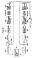
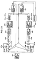
- Figure 16 is a block diagram of a displacement controller for a fine positioning device according to this invention.
- piezoelectric actuators 26a,26b parallel flexible-beam displacement mechanisms 29a,29b
- strain gauges 90a1-90a4,90b1-90b4 which are all the same as their corresponding elements shown in Figure 14A.
- Numeral 95 indicates a displacement setting device for setting the degree of a target displacement of the parallel flexible-beam displacement mechanisms shown in Figure 14A.
- the displacement setting device 95 outputs strain values ⁇ 1, ⁇ 2 corresponding to the target displacement (see Figure 17). Namely, different target displacements are established for a fine positioning device making use of a parallel flexible-beam displacement mechanism.
- a measurement is conducted in advance to determine outputs (strain values) ⁇ 1, ⁇ 2 from the Wheatstone bridge circuits 91a,91b whenever each of the target displacements has been achieved.
- the thus-measured strain values are stored in relation to their corresponding displacements in the displacement setting device 95.
- the target displacement L is input to the displacement setting device 95, its corresponding strain values ⁇ 1, ⁇ 2 which have been measured and stored as described above are read out and then output.
- FIG. 17 The relation between such strain values and displacements is shown in Figure 17, in which displacements are plotted along the axis of abscissas while strains are plotted along the axis or ordinates.
- a straight line A1 represents output characteristics of the Wheatstone bridge circuit 91a while a straight line A2 represents output characteristics of the Wheatstone bridge circuit 91b.
- the displacement is L
- a strain value ⁇ 1 is output from the Wheatstone bridge 91a while another strain value ⁇ 2 is output from the Wheatstone bridge circuit 91b.
- the displacement L can be obtained when a voltage is applied to the piezoelectric actuator 26a so as to make the output of the Wheatstone bridge circuit 91a become the value ⁇ 1 and another voltage is applied at the same time to the piezoelectric actuator 26b so as to make the output of the Wheatstone bridge circuit 91b become the value ⁇ 2. If the relation between such displacements and strain values has already been known, it is only necessary to store their relation in the displacement setting device 95 without need for the above-described measurement.
- Figure 16 also shows transducers 96a,96b for converting (amplifying) individual strain values ⁇ 1, ⁇ 2 into corresponding signal voltages v1,v2 required for further processing, adders 97a,97b,98a,98b, and amplifiers 99a,99b.
- Numerals 100a,100b indicate respectively strain signal generating circuits 100a, 100b equipped with the Wheatstone bridge circuits 91a,91b and amplifier circuits for amplifying the outputs ⁇ 1 ⁇ , ⁇ 2 ⁇ of the Wheatstone bridge circuits 91a,91b into signal voltages V 1 ⁇ ,V 2 ⁇ required for processing the outputs ⁇ 1 ⁇ , ⁇ 2 ⁇ as signals.
- Designated at numeral 101 is an indicator, which receives output signals from the strain signal generating circuits 100a,100b and indicates a displacement of the fine positioning device on the basis of these signals.
- the displacement controller When a value is input and set in the displacement setting device 95 in order to displace the fine positioning device, which makes use of the parallel flexible-beam displacement mechanism, by the displacement L, the strain values ⁇ 1, ⁇ 2 corresponding to the value L are read out in the displacement setting device 95 and are then output separately from the displacement setting device 95.
- the strain value ⁇ 1 is input in the transducer 96a, in which it is converted into the signal v1, followed by its input to the amplifier 99a via the adder 98a.
- the amplifier 99a outputs a voltage of such a level that is proportional to the input signal v1 and is also suitable for driving the piezoelectric actuator 16a, and then applies the voltage to the actuator 26a.
- the parallel flexible beams 24a1,24a2 of the parallel flexible-beam displacement mechanism 29a are flexed and strains are caused to occur in the strain gauges 90a1-90a4 Accordingly, the signal v1, proportional to the strain value ⁇ 1, detected by the Wheatstone bridge circuit 91a is output from the strain signal generating circuit 100a.
- the signal v1 is input to the adder 97a.
- the difference ⁇ v between the signal v1 and signal v 1 ⁇ is obtained.
- the adder 98a the difference ⁇ v and the signal v1 are added together and the resultant signal (v1 + ⁇ v) is input to the amplifier 99a.
- a feedback control such as that described above is thereafter repeated so as to adjust voltages to be applied to the piezoelectric actuators 26a,26b respectively.
- the strain value ⁇ 1 is output from the Wheatstone bridge circuit 91a composed of the strain gauges 90a1-90a4.
- the parallel flexible beams 24a1,24a2 of the parallel flexible-beam displacement mechanism 29a are flexed to the predetermined degree.
- Similar processing is also performed with respect to the signal ⁇ 2 and the strain value ⁇ 2 is output eventually from the Wheatstone bridge circuit 91b.
- the fine positioning device is allowed to undergo a displacement exactly by the target displacement L.
- signals output from the strain signal generating circuits 100a,100b are input to the indicator 101, so that displacements corresponding to the signals are indicated and the displacement L is finally indicated there.
- strain values corresponding to the target displacement are output and then compared respectively with the strain values from the corresponding strain signal generating circuits.
- the degree of deformation of each of the parallel flexible beams 24a1,24a2,24b1,24b2 is detected by using strain gauges.
- the degree of the above deformation may however be feasible by another detection means.
- One embodiment making use of said another detection means will hereinafter be described.
- Figures 18A and 18B are side views of another parallel flexible-beam displacement mechanism which can be controlled by the displacement controller. Elements of structure shown in Figure 18A identical to those depicted in Figure 14A are identified by the same reference numerals and letters and their description is omitted herein.
- Numeral 105c indicates a support portion made of a rigid material. The support portion 105c is formed by extending the rigid portions 21a,21b in parallel to the parallel flexible beams 24a2,24b2 and the lower wall 21c ⁇ of the rigid portion 21c.
- Designated at numerals 106a,106b are capacitance displacement detectors fixed on the support portion 105c respectively. The capacitance displacement detectors 106a,106b detect the spacing ⁇ between their upper surfaces and the lower wall 21c ⁇ . The capacitance displacement detectors 106a,106b will be described subsequently.
- the capacitance displacement detectors 106a,106b can also be applied to the displacement controller depicted in Figure 16 by using the degrees of displacements of the parallel flexible-beam displacement mechanisms 29a,29b and a value detected by each of the capacitance displacement detectors 106a,106b provided that when a desired displacement is set in the displacement setting device 95 shown in Figure 16, the corresponding displacements of the parallel flexible-beam displacement mechanisms 29a,29b are output respectively.
- Figure 18B is a side view of the parallel flexible-beam displacement mechanism in which the points of attachment of the capacitance displacement detectors are different from those depicted in Figure 18A. Elements of structure identical to those shown in Figure 18A are identified by the same reference numerals and letters.
- the capacitance displacement detectors 106a,106b are fixed respectively on the upper surfaces of holding portions 107a,107b which extend inwardly from the rigid portion 21c and hold the piezoelectric actuators 26a,26b thereon.
- the capacitive displacement detectors 106a,106b are located at positions facing the parallel flexible beams 24a1,24b1 respectively.
- FIGS 19A and 19B are a cross-sectional view and bottom view of a capacitance displacement detector
- Figure 19C is a circuit diagram of the detection circuit.
- a description will hereinafter be made of the capacitance displacement detector 106a alone.
- designated at numeral 106a1 is a columnar central electrode while the numeral 106a2 indicates a cylindrical electrode facing the circumferential wall of the central electrode 106a1.
- Designated at numeral 106a3 is a dielectric interposed between the central electrode 106a1 and cylindrical electrode 106a2.
- the central electrode 106a1 and cylindrical electrode 106a2 are constructed to have an identical horizontal cross-sectional area as viewed in Figure 19B.
- This electrostatic capacity C a is detected by the detection circuit shown in Figure 19c, in which there are shown an oscillator 110, a capacitor 111 giving a standard electrostatic capacity C y , an AC amplifier 112, the capacitance displacement detector 106a, an AC/DC converter 113, a DC amplifier 114, and a low-pass filter 115.
- This signal is converted to a direct current by the AC/DC converter 113, is subjected to a span adjustment at the DC amplifier 114 and is then shaped at the low-pass filter 115. Consequently, the signal e a is expressed as follows: The signal e a is hence output as a detection signal of the spacing ⁇ . Namely, the spacing ⁇ can be detected by the capacitance displacement detector 106a.
- the fine positioning device capable of performing translational displacements is referred to by way of example. It is however apparent that the controller of this invention can also be applied to the fine positioning device depicted in Figure 9A which can perform angular displacements.
- the above displacement controller can perform a high-accuracy displacement control and can be constructed in small dimensions and at a low price. It can therefore be provided easily with each fine positioning device.
- the above displacement controller for the fine positioning device has such a construction that a feedback control is effected by detecting translational displacements of both parallel flexible displacement mechanisms of the symmetrical type.
- Another displacement controller may also be contemplated that in addition to the above-mentioned displacement control, the degree of a strain caused by translational displacement components of both parallel flexible-beam displacement mechanisms and the degree of a strain caused by an angular displacement (the angle ⁇ shown in Figure 14B) are detected separately and an accurate displacement control is effected based on these detected values.
- a displacement controller according to another embodiment of control similar to the aforementioned embodiment will next be described.
- the detection of each strain value is conducted by a Wheatstone bridge circuit like the above-described displacement controller. Reflecting differences in the manner of control, different detection means are employed for the detection of the degree of each strain.
- the strain detection means in this displacement controller will be described first of all.
- FIGS 20A and 20B are circuit diagrams of strain value detection circuits respectively.
- numerals 90a1,90a2,90a3,90a4,90b1,90b2,90b3, 90b4 are respectively strain gauges shown in FIGURE 14A.
- a Wheatstone bridge circuit 121 for detecting the degree of each strain by translational displacements of the parallel flexible-beam displacement mechanisms 29a,29b
- another Wheatstone bridge circuit 122 for detecting the degree of each strain by angular displacements of the parallel flexible-beam displacement mechanisms 29a,29b.
- Letter B indicates a DC power supply.
- the piezoelectric actuator 26a,26b are each applied with a voltage and displacements are caused to occur as shown in Figure 6B.
- the strain gauges 90a2,90b1 contract and the strain gauges 90a1,90b2 expand and their resistance values hence vary correspondingly.
- the displacements are then output as a strain value ⁇ 10.
- the displacements are therefore output as the sum of these variations, i.e., as a strain value ⁇ 10.
- the strain gauges 90a4,90b3 contract while the strain gauges 90a3,90b4 expand.
- a strain value ⁇ 20 is hence output in such a form that their changes in resistance are cancelled each other.
- the strain value ⁇ 20 is 0.
- the strain value ⁇ 20 is not 0 because an angular displacement is contained.
- the strain value ⁇ 20 in such a state as mentioned above will be considered to be positive while the strain value ⁇ 20 of rotary displacement in the opposite direction will be assumed to be negative.
- FIG 21 is a block diagram of another displacement controller according to this invention, which is suitable for use with a fine positioning device.
- piezoelectric actuators 26a,26b parallel flexible-beam displacement mechanisms 29a,29b, and strain gauges 90a1-90a4,90b1-90b4. They are identical to their corresponding elements shown in Figure 14A.
- Designated at numeral 125 is a displacement setting device for setting the degree of a target displacement of the parallel flexible-beam displacement mechanism depicted in Figure 14A.
- the displacement setting device 125 When a target displacement L is set, the displacement setting device 125 outputs a value V which is proportional to the above-described strain value ⁇ 10 corresponding to the target displacement L. In other words, different target displacements are established for the above fine positioning device.
- a measurement is conducted in advance to determine an output (strain value) ⁇ 10 from a Wheatstone bridge circuit 121 whenever each of the target displacements has been achieved.
- the thus-measured values V are stored in relation to the respective strain values in the displacement setting device 125.
- the displacement setting device 125 reads out the corresponding stored value V and outputs same.
- the characteristics of the degree of displacements and strain values have already been known, it is only necessary to store the above characteristics in the displacement setting device 125 without need for the above-described measurement.
- adders 126a,126b there are also depicted adders 126a,126b, gain controllers 127a1,127a2,127b1,127b2, integrators 128a,128b, and adders 129a,129b.
- the gain controllers 127a1, 127a2,127b1,127b2 and integrators 128a,128b serve to change the size of feedback signals per unit time. They have such a function that the hunting problem of the control system is prevented by adjusting the level of the gain of each of the gain controller 127a1-128b2, thereby avoiding positional deviation and achieving the prompt displacement to the target position.
- Designated at numerals 130a,130b are amplifiers which amplify in proportion to the voltage V the outputs of the adders 129a,129b to the drive levels of the corresponding piezoelectric actuators 26a,26b respectively.
- Numeral 131 indicates a strain signal generating circuit which includes the Wheatstone bridge circuit 121 and amplifies the output ⁇ 10 of the Wheatstone bridge circuit 131 to a voltage of a predetermined level.
- the output of the strain signal generating circuit 131 is indicated by a value V10.
- the numeral 132 indicates another strain signal generating circuit which includes the Wheatstone bridge circuit 122 and amplifies the output ⁇ 20 of the Wheatstone bridge circuit 122 to a voltage of a predetermined level.
- the output of the strain signal generating circuit 132 is indicated by a value V20.
- Designated at numeral 133 is an indicator for indicating the degree of a displacement on the basis of its corresponding outputs from the strain signal generating circuits 131,132.
- the flexible beams 24a1,24a2 of the parallel flexible-beam displacement mechanism 29a are flexed and a strain is correspondingly developed in each of the strain gauges 90a1-90a4.
- the voltage V output from the displacement setting device 125 is also amplified at the amplifier 130b. The thus-amplified voltage then drives the piezoelectric actuator 26b, so that the flexible beams 24b1,24b2 of the parallel flexible-beam displacement mechanism 29b are flexed and a strain is hence developed in each of the strain gauges 90b1-90b4.
- the strain gauges 90a1,90a2,90b1,90b2 are connected to the strain signal generating circuit 131 in such a way that the strain gauges form the Wheatstone bridge circuit 121 depicted in Figure 20A.
- a strain value ⁇ 10 corresponding to a translational displacement is detected.
- the strain value ⁇ 10 is then amplified to the signal V10 which is proportional to the strain value, and the signal V10 is output from the strain signal generating circuit 131.
- the strain gauges 90a3,90a4, 90b3,90b4 are connected to the strain signal generating circuit 132 in such a way that the strain gauges form the Wheatstone bridge circuit 122 depicted in Figure 20B.
- a strain value ⁇ 20 corresponding to an angular displacement is detected.
- the amplified signal V20 is then output.
- the signal V10 from the strain signal generating circuit 131 is input to each of the adder 126a,126b, where the signal is added to the signal V so as to obtain their difference (V-V10).
- the signal V20 from the strain signal generating circuit 132 is input to each of the adders 126a,126b.
- the displacement controller of this embodiment can obtain high-accuracy translational displacements like the displacement controller of the preceding embodiment. Since the displacement controller can be formed at a low price into extremely small dimensions, it can be provided with each parallel flexible-beam displacement mechanism.
- a displacement controller for producing angular displacements only in a radial flexible-beam displacement mechanism may also be constructed in substantially the same manner as the preceding displacement controllers. Such a displace ment controller will hereinafter be described. A description will however be made first of all of radial flexible-beam displacement mechanisms, strain gauges applied to the mechanisms and strain value detection means, because strain values are detected by Wheatstone bridge circuits making use of the strain gauges and displacements are controlled on the basis of the strain values thus detected.
- Figure 22 is a side view of the same radial flexible-beam displacement mechanism as that shown in Figure 9A. Elements of structure identical to their corresponding elements depicted in Figure 9A are identified by like reference numerals and letters. Designated at numerals 135a1,135a2 are strain gauges cemented on the radial flexible beam 58a1. Numerals 135a3,135a4 indicate strain gauges cemented on the radial flexible beam 58a2, while numerals 135b1,135b2 indicate strain gauges cemented on the radial flexible beam 58b2.
- each of the radial flexible beams 58a1-58b2 is flexed to produce a predetermined angular displacement.
- the degree of this angular displacement is proportional to the voltage applied to each of the piezoelectric actuators 60a,60b.
- a strain is developed in each of the strain gauges 135a1-135b2 so that the resistance of each strain gauge changes. It is hence possible to determine the degree of strain of each of the radial flexible beams 58a1-59b2 by using these strain gauges 135a1-135b2.
- Figures 23A - 23C are circuit diagrams of such strain value detection circuits respectively.
- Figure 23A shows a Wheatstone bridge circuit 136 for detecting a strain value ⁇ 30 due to each angular displacement
- Figure 23B illustrates a Wheatstone bridge circuit 137 for detecting a strain value ⁇ 40 due to each translational displacement along the x-axis
- Figure 23C depicts a further Wheatstone bridge circuit 138 for detecting a strain value ⁇ 50 due to each translational displacement along the z-axis.
- the Wheatstone bridge circuits 136,137,138 can be formed by cementing their respective four strain gauges 135a1-135b4.
- FIG 24 is a block diagram of the displacement controller, in which elements of structure identical to their corresponding elements in Figure 21 are identified by like reference numerals and letters. Description of such like elements of structure is omitted herein.
- the displacement setting device 125 serves to set angular displacements.
- Designated at numerals 60a,60b are the piezoelectric actuators shown in Figure 22, while the radial flexible-beam displacement mechanisms shown in Figure 22 are designated at numerals 63a,63b respectively.
- the strain gauges illustrated in Figure 22 are indicated at numerals 135a1-135b4,135b1,135b2 respectively.
- strain signal generating circuit 140 includes the Wheatstone bridge circuit 136 shown in Figure 23A
- strain signal generating circuit 141x includes the Wheatstone bridge circuit 137 shown in Figure 23A
- strain signal generating circuit 141z includes the Wheatstone bridge circuit 138 shown in Figure 23C.
- the drive and control of the radial flexible-beam displacement mechanism 63a is performed by a loop which runs through the adder 126a, gain controllers 127a1,127a2, integrator 128a, adder 129a, amplifier 130a, piezoelectric actuator 60a, radial flexible-beam displacement mechanism 63a, strain gauges 135a1-135a4,135b1,135b2, and strain signal generating circuits 140,141x,141z.
- the drive and control of the radial flexible-beam displacement mechanism 63b is performed by a loop which runs through the adder 126b, gain controllers 127b1,127b2, integrator 128b, adder 129b, amplifier 130b, piezoelectric actuator 60b, radial flexible-beam displacement mechanism 63b, strain gauges 135a1-135a4,135b1,135b2 and strain signal generating circuits 140,141x,141z.
- the output V40 of the strain signal generating circuit 141x and the output V50 of the strain signal generating circuit 141z are both controlled to 0, in other words, the translational displacements along the x- and z-axes contained in the angular displacement are eliminated and at the same time, the output V30 of the strain signal generating circuit 140 is brought into conformity with the output V of the displacement setting device 125.
- This operation of the displacement controller is similar to that of the preceding displacement controller and its detailed description is omitted herein.
- the displacement controller of this embodiment can obtain high-accuracy angular displacements. Since the displacement controller can be formed at a low price into extremely small dimensions, it can be provided easily with each radial flexible-beam displacement mechanism.
- FIG 25 is a perspective view of the radial flexible-beam displacement mechanisms 78M ya ,78M yb taken out solely from the fine positioning device depicted in Figure 12.
- elements of structure identical to their corresponding elements in Figure 12 are identified by like reference numerals and letters and their description is omitted herein.
- Designated at numerals 145a1-145b2 are strain gauges cemented respectively at illustrated positions on the respective radial flexible-beam displacement mechanisms 78M ya ,78M yb .
- each of the radial flexible-beam displacement mechanisms 78M ya ,78M yb undergoes an identical angular displacement in the radial flexible-beam displacement mechanism of the above-described construction.
- the fine motion table 82 is obviously unable to undergo a perfect angular displacement but is subjected to a twisting deformation, unless the angular displacements of the radial flexible-beam displacement mechanisms 78M ya ,78M yb are identical to each other.
- FIGS 26A and 26B are circuit diagrams of strain value detection circuits respectively.
- the strain gauges shown in Figure 25 are identified at numerals 145a1-145a4,145b1,145b2 respectively.
- Numeral 146 indicates a Wheatstone bridge circuit for detecting a strain value ⁇ 60 corresponding to each angular displacement
- numeral 147 indicates a Wheatstone bridge circuit for detecting a strain value ⁇ 70 corresponding to a displacement caused by each twisting deformation.
- the displacement controller for such radial flexible-beam displacement mechanisms 78M ya ,78M yb is substantially the same as the displacement controller depicted in Figure 24.
- a strain signal generating circuit including the Wheatstone bridge circuit 146 and another strain signal generating circuit including the Wheatstone bridge circuit 147 are provided in place of the strain signal generating circuits 140,141x,141z.
- Each output signal of the former strain signal generating circuit is input directly to the adders 126a,126b, while each output signal of the latter strain signal generating circuit is input to the adders 126a,126b.
- the other construction is the same as that of the controller depicted in Figure 24. Its operation is also similar to the operation of the controller shown in Figure 24. By the controller, it is possible to perform a displacement control similar to that for a symmetrical radial flexible-beam displacement mechanism.
- capacitance displacement detectors such as those shown in Figures 18A - 19C may be used in place of the strain gauges in the above radial flexible-beam displacement mechanisms.
- Figure 27 is a block diagram illustrating characteristics of a fine positioning device depicted for example in Figure 10.
- the fine positioning device is constructed in combination of six fine motion units which include three sets of parallel flexible-beam displacement mechanisms for producing translational displacements along the x-, y- and z-axes respectively and three sets of radial flexible-beam displacement mechanisms for producing angular displacements about the x-, y- and z-axes respectively.
- drive voltages V1-V6 applied to the fine motion units respectively and displacements U1-U6 occurred in the respective fine motion units (fine motion unit displacements) by the corresponding drive voltages V1-V6.
- Letters x, y,z, ⁇ x , ⁇ y and ⁇ z indicate displacement components at a certain specific point (hereinafter called “standard point") on the fine motion table 43 of the fine positioning device depicted in Figure 10. These displacements and displacement components will hereinafter be called “displacements at the standard point” and “displacement components at the standard point” respectively.
- Letters B1-B6 indicate the gain characteristics between drive voltages V1-V6 and the displacements U1-U6 of the corresponding fine motion units.
- Letter C indicates displacement interference characteristics representing the relation between the displacements U1-U6 of the respective fine motion units and the displacement components x, y, ... ⁇ z at the standard point.
- the voltage V1 is applied to a desired fine motion unit (which may be constructed, for example, of the parallel flexible-beam displacement mechanisms 16F xa ,16F xb in the case of the fine positioning device depicted in Figure 10) in order to make the standard point undergo a translational displacement along the x-axis.
- the fine motion unit then produces a fine motion unit displacement U1.
- the drive voltages V2-V6 and fine motion unit displacements U2-U6 are all 0. It would be ideal that upon production of the displacement U1 in the fine motion unit, the displacement component x occurs at the standard point and the other displacement components y- ⁇ z at the standard point become 0.
- the other displacement components at the standard point are not reduced to 0 although they are small. It is hence unavoidable that certain values are produced with respect to some or all of the other displacement components. In other words, displacement components other than the translational displacement along the x-axis occur.
- FIG. 28 is a block diagram of a displacement controller for a multi-axis fine positioning device.
- numeral 150 indicates a fine positioning device composed of plural fine motion units, such as that illustrated in Figure 10.
- Designated at numeral 151 is a target displacement setting unit, in which a target value of the standard point of the fine positioning device 150 is set.
- Numeral 152 indicates a characteristic compensation computing unit 152, which receives a target displacement from the target displacement setting unit 151, performs predetermined computation on the basis of the target displacement, and outputs a drive voltage to each fine motion unit so as to produce the desired displacement at the standard point of the fine positioning device 150.
- the characteristic compensation computing unit 152 The computation of the characteristic compensation computing unit 152 will next be described. Let's now assume by way of example that the displacement component x is obtained at the standard point (the other displacement components y- ⁇ z being 0). In the characteristics shown in Figure 27, the desired standard-point displacements (x, 0, 0, ...., 0) cannot be obtained unlike the above-mentioned operation even when the drive voltage V1 is applied to one of the fine motion units and the fine motion unit displacement U1 is produced. In order to obtain such a desired standard-point displacement, it is necessary to produce displacements in the other fine motion units so as to cancel small displacement components occurred respectively in the standard-point displacement components y- ⁇ z which are supposed to be 0 in principle. When a target displacement (x, 0, ...., 0) is input to the target displacement setting unit 151, the characteris tic compensation computing unit 152 computes how much voltage should be applied to which fine motion unit to produce a fine motion unit displacement.
- the 36 constants C11-C66 can be known by conducting at least 6 times an operation that the respective standard-point displacements x- ⁇ z are measured upon production of certain displacements in six fine-motion units respectively, the respective standard-point displacements x- ⁇ z are measured upon production of different displacements in the same fine motion units, and then the resulting equation is then solved.
- the measurement of these standard-point displacement components x- ⁇ z can be effected by a sensor provided externally, such as laser displacement sensor.
- the matrix ⁇ D ji ⁇ in the equation (5) can be determined by the same method as that employed to determine the matrix ⁇ C ji ⁇ in the determinant (2).
- the characteristic compensation computing unit 152 has as compensation characteristics the inverse characteristics ⁇ D ji ⁇ 1 of the characteristic matrix ⁇ D ji ⁇ determined by the above equation (5). Computation is performed in accordance with these inverse characteristics ⁇ D ji ⁇ 1.
- this displacement controller When a target displacement (which will be expressed by (X 0j ⁇ ) of the standard point is set in the target displacement setting unit 151, this target displacement ⁇ X 0j ⁇ is input to the characteristic compensation computing unit 152 so that computation is performed in accordance with the above equation (6). This computation apparently results in a solution obtained by substituting the target displacement ⁇ X 0j ⁇ to the standard-point displacement ⁇ X j ⁇ in the equation (6).
- a drive voltage ⁇ V i ⁇ obtained from the above computation is input to a fine positioning device 150, a displacement ⁇ X 0j ⁇ occurs at its standard point.
- ⁇ D ji ⁇ ⁇ C ji ⁇ B i ⁇
- the compensation characteristics ⁇ D ji ⁇ 1 of the characteristic compensation computing unit 152 can therefore be obtained as an inverse matrix of the product of the matrices ⁇ B i ⁇ and ⁇ C ji ⁇ .
- the fine motion unit displacement ⁇ U i ⁇ in the equations (3) and (4) is measured by strain gauges provided with each fine motion unit as shown in Figure 14A or 22. Needless to say, the measurement is also feasible by a displacement sensor other than strain gauge as described before.
- the displacement controller of this embodiment can obtain displacements of extremely high accuracy even if it is manufactured with ordinary machining and assembly accuracy.
- Figure 29 is a block diagram of a still further displacement controller for a multi-axis fine positioning device, in which elements of structure identical to their corresponding elements shown in Figure 28 are identified by like reference numerals and letters. Description of these elements is omitted herein.
- Numeral 153 indicates an external displacement sensor for detecting each displacement of the standard point of the fine positioning device 150. The external displacement sensor 153 outputs an electrical signal proportional to the displacement detected.
- a laser displacement sensor is generally used as the external displacement sensor. The laser displacement sensor is provided outside the fine positioning device 150 so as to detect any displacement of its standard point.
- Designated at numeral 154 is a subtractor for computing the difference between each detection output ⁇ X j ⁇ of the external displacement sensor 153 and the target displacement ⁇ X 0j ⁇ set in the target displacement setting unit 151.
- Numeral 155 indicates a constant generating unit for generating a predetermined constant K1
- numeral 156 designates a multiplying unit for multiplying by the constant K1 each difference ⁇ X j ⁇ output from the subtractor 154.
- Designated at numeral 157 is an adding unit for adding together the target displacement ⁇ X 0j ⁇ and each value obtained at the multiplying unit 156.
- the displacement controller of this embodiment has such a construction that the so-called feedback control is applied to the construction of the displacement controller shown in Figure 28.
- the constant K1 is a feedback gain.
- this displacement controller When a target displacement ⁇ X 0j ⁇ of the standard point is set in the target setting unit 151, a drive voltage ⁇ V i ⁇ is output from the characteristic compensation computing unit 152 like the preceding embodiment so that the standard point of the fine positioning device 150 undergoes a displacement.
- the constant K1 is multiplied to the thus-computed difference ⁇ X j ⁇ at the multiplying unit 156.
- the product K1 ⁇ x j ⁇ is then input to the adding unit 157, so that the target displacement ⁇ X 0j ⁇ is adjusted.
- This adjusted value is then input to the characteristic compensation computing unit 152 and a new drive voltage ⁇ V i ⁇ is then output responsive to the adjusted value, whereby the displacement of the standard point of the fine positioning device 150 is adjusted.
- Any deviation of the displacement of the standard point relative to the target displacement ⁇ X 0j ⁇ is gradually corrected by repeating the above-mentioned series of operations.
- the standard point is stopped when the displacement has coincided with the target displacement.
- a proportional control method in which the difference ⁇ X j ⁇ is multiplied by the feedback gain K1 is used in order to perform the feedback control effectively.
- the present invention is however not necessarily limited to the use of such a proportional control method. Needless to say, so-called integral control or differential control may also be used. Therefore, the signal added to the target displacement ⁇ X 0j ⁇ at the adding unit 157 may be called in more generic term, i.e., "a signal corresponding to the difference ⁇ X j ⁇ ".
- FIG 30 is a block diagram of a still further displacement controller for a multi-axis fine positioning device. Elements of structure identical to their corresponding elements depicted in Figure 29 are identified by like reference numerals, and their description is omitted herein.
- Designated at numeral 150c is an internal displacement sensor typified by strain gauges (see Figures 14A and 22) cemented on each fine motion unit or a Wheatstone bridge circuit formed of such strain gauges.
- the internal displacement sensor 150c output a signal proportional to each displacement ⁇ U i ⁇ of each fine motion unit. Displacement indicators of other types may also be used obviously.
- Numeral 155 ⁇ indicates a constant generating unit for generating a feedback gain K2.
- Designated at numeral 158 is a displacement transducer for converting a target displacement signal ⁇ X 0j ⁇ into its corresponding fine motion unit displacement signal ⁇ U 0i ⁇ .
- the present embodiment constitutes a feedback control system as apparent from the drawing.
- the displacement transducer 158 In order to have the displacement transducer 158 produce the displacement ⁇ X 0j ⁇ at the standard point of the fine positioning device 150 as described above when the target displacement signal (X 0j ⁇ is input, the displacement transducer 158 has a function that determines how each fine motion unit should be displaced. In order to exhibit this function, characteristics correlating the standard point displacement ⁇ X j ⁇ with the fine motion unit displacement ⁇ U i ⁇ are essential. These characteristics are indicated by the displacement interference characteristics ⁇ C ji ⁇ in the equation (4). Thus, the displacement transducer 158 has inverse characteristics ⁇ C ji ⁇ 1of the displacement interference characteristics ⁇ C ji ⁇ . By performing computation in accordance the inverse characteristics ⁇ C ji ⁇ 1, it is possible to output the fine motion unit displacement signal ⁇ U 0i ⁇ for obtaining the target displacement ⁇ X 0j ⁇ .
- the fine motion unit displacement signal ⁇ X 0j ⁇ for producing the target displacement ⁇ X 0j ) at the standard point of the fine positioning device 150 is computed at the displacement transducer 158 and is then output.
- the target displacement ⁇ X 0j ) is input to the characteristic compensation computing unit 152, its corresponding drive voltage ⁇ V 0i ⁇ is output.
- This drive voltage ⁇ V 0i ) is converted into the drive voltage ⁇ V i ⁇ by way of the adding unit 157.
- the drive voltage ⁇ V i ⁇ is then applied to each fine motion unit of the fine positioning device 150.
- the parallel and/or radial flexible beams composing each fine motion unit are hence deformed to make the fine motion unit undergo a displacement, whereby the standard point of the fine positioning device 150 is displaced.
- These strain gauges are formed into a Wheatstone bride circuit as described above so that a signal proportional to the displacement of the fine motion unit is output from the Wheatstone bridge circuit. Namely, the displacement ⁇ U i ⁇ of each fine motion unit is output from the internal displacement sensor 150c.
- the product, K2 ⁇ U i ⁇ , is then input to the adding unit 157, whereby the drive voltage ⁇ V 0i ⁇ of the characteristic compensation computing unit 152 is corrected to output a new drive voltage ⁇ V i ⁇ so that the displacement of the standard point of the fine positioning device 150 is corrected.
- the deviation of the standard point from the target displacement ⁇ X 0j ⁇ is corrected gradually.
- the standard point is stopped when the displacement has coincided with the target displacement.
- the inverse charac teristics ⁇ C ji ⁇ 1 of the displacement interference characteristics ⁇ C ji ⁇ are used by way of example for computation at the displacement transducer 158. It is a prerequisite for the use of such inverse characteristics to employ an ideal fine motion unit that undergoes displacements in the direction of its main displacement U i and does not undergo any displacements in other directions as indicated in Figure 27 and by the above equation (1), when the drive voltage ⁇ V i ⁇ is applied to a desired fine motion unit. Such a situation however does not exist practically when observed strictly.
- All interference displacement components including the above-mentioned new interference component are however contained in the displacement interference characteristics ⁇ C ji ⁇ as defined by the equations (2) and (4), provided that ⁇ C ji ⁇ as defined by the equations (2) and (4) is defined newly as the relation between the fine motion unit displacement ⁇ U i ⁇ , which occurs upon application of the drive voltage ⁇ V i ⁇ to each of the fine motion units composing an actual fine positioning device, and the standard point displacement ⁇ X j ⁇ .
- the displacement controller of the above embodiment can perform displacements of still higher accuracy.
- the displacement controller has remarkable effects as will be described below. Namely, like the displacement controller shown in Figure 29, laser displacement sensors capable of performing detection on the order of micrometers are used as external displacement sensors for detecting displacements of the standard point of a fine positioning device.
- the mounting and adjustment of these laser displacement sensors are extremely cumbersome. A lot of labor and time are therefore required for their mounting and adjustment and moreover, such laser displacement sensors per se are extremely expensive.
- the above displacement controller does not use such external displacement sensors but makes use of the internal displacement sensors which the fine positioning device itself has. Therefore, the above displacement controller is extremely simple in structure and can be constructed easily at a low price.
Landscapes
- Engineering & Computer Science (AREA)
- Mechanical Engineering (AREA)
- Human Computer Interaction (AREA)
- Manufacturing & Machinery (AREA)
- Physics & Mathematics (AREA)
- General Physics & Mathematics (AREA)
- Automation & Control Theory (AREA)
- Control Of Position Or Direction (AREA)
- Container, Conveyance, Adherence, Positioning, Of Wafer (AREA)
Abstract
Description
- This invention relates to a fine positioning device suitable for use in an apparatus which requires fine adjustment on the order of micrometers, such as semiconductor fabrication apparatus or electron microscope, and also to a displacement controller for such a fine positioning device.
- In various fields of technology, there has recently been a strong demand for devices which enable fine adjustment of displacements on the µm order. As a typical technical field, may be mentioned semiconductor fabrication apparatus employed in the fabrication processes of LSI (large-scale integrated circuits) and super large-scale integrated circuits, such as mask aligners, electron-beam drawing machines and the like. In these apparatus, it is necessary to achieve fine positioning of the µm order. The degree of integration increases and products of higher performance can be fabricated, as the positioning accuracy is improved. Such fine positioning is required not only for the above-described semiconductor fabrication apparatus but also for a variety of high-magnification optical apparatus, led by electron microscopes, and the like. Improved accuracy contributes significantly to the development of advanced technology such as biotechnology, space development, etc.
- As such fine positioning devices, a variety of devices have heretofore been proposed, for example, as shown in a Japanese magazine, "Kikai Sekkei (Machine Designing)", 27(1), 32-36, January 1983. Of such fine positioning devices, those making use of parallel springs and fine motion actuators are considered to be superb in that inter alia, they do not require cumbersome displacement reducing mechanisms and their structures are simple. Accordingly, a fine positioning device of the above sort will hereinafter be described with reference to Figure 1.
- Figure 1 is a side view of a conventional fine positioning device, in which there are illustrated a support table 1, planar
parallel springs 2a,2b fixed in parallel to each other on the support table 1, and a fine motion table 3 supported on theparallel spring 2a,2b and having a high degree of rigidity. Designated atnumeral 4 is a fine motion actuator mounted between the support table 1 and fine motion table 3. Thefine motion actuator 4 makes use of a piezoelectric element, electromagnetic solenoid or the like, which is energized to apply a force to the fine motion table 3 along the x-axis of the coordinate system depicted in the figure. - The
parallel springs 2a,2b, reflecting their structure, have low rigidity in the direction of the x-axis but high rigidity in the direction of the z-axis and in the direction of the y-axis (namely, in the direction perpendicular to the drawing sheet). When thefine motion actuator 4 is energized, the fine motion table 3 thus undergoes a displacement practically along the x-axis only and no substantial displacements take place in the other directions. - Figure 2 is a perspective view of another conventional fine positioning device which is readily conceivable from the devices disclosed by way of example in the above-mentioned magazine. In the figure, there are shown a support plate 6, a pair of planar
parallel springs parallel springs parallel springs parallel spring parallel spring parallel spring parallel springs - When the force Fx is applied to the fine motion table 10, the
parallel springs parallel springs parallel springs parallel springs parallel springs - As described above, the device shown in Figure 2 can perform positioning along two axes whereas the device illustrated in Figure 1 is a one-axis positioning device.
- In each of the devices shown respectively in Figures 1 and 2, the fine motion table 10 is displaced linearly along the specific axis. On the other hand, Japanese Patent Publication No. 50433/1982 discloses a fine positioning device in which a fine motion table is caused to undergo a fine angular displacement about a specific axis. This fine positioning device will next be described with reference to Figure 3.
- Figure 3 is a partially cut-away perspective view of a conventional fine positioning device which makes use of fine angular displacements. In the figure, numeral 11 indicates a fixed central portion in the form of a cylindrical column and numerals 11a,11b,11c designate vertical slots formed with an equal interval, along the length of the fixed central portion, in the circumferential wall of the fixed central portion 11. There are also depicted a ring-
shaped stage 12 provided movably about the fixed central portion 11 and U-like metal members 12a₁-12a₃, 12b₁-12b₃,12c₁-12c₃ secured fixedly on thestage 12 in opposition to the vertical slots 11a,11b,11c respectively. Designated atnumeral 13 are bimorph cells mounted between the individual vertical slots 11a,11b, 11c and their corresponding U-like metal members 12a₁-12c₃, whilenumeral 13A indicates beads fixed on thebimorph cells 13 at locations where thebimorph cells 13 engage their corresponding U-like metal members 12a₁-12c₃. The fixed central portion 11,stage 12 and individual U-like metal members 12a₁-12c₃ are all rigid. Here, the above-mentionedbimorph cells 13 are described in brief with reference to Figure 4. - Figure 4 is a perspective view of one of the bimorph cells 12a₁-12c₃. In the figure, there are shown
piezoelectric elements common electrode 13c provided between thepiezoelectric elements piezoelectric elements common electrode 13c interposed therebetween. Designated atnumerals piezoelectric elements piezoelectric element 13a is caused to contract is applied between thesurface electrode 13d andcommon electrode 13c and at the same time, another voltage of such a polarity that thepiezoelectric element 13b is caused to expand is applied between thesurface electrode 13e andcommon electrode 13c, thepiezoelectric elements bimorph cell 13 is deformed as a whole as shown in the figure. Owing to this property, thebimorph cell 13 can provide a greater degree of displacement compared with a single piezoelectric element. - In the device shown in Figure 3, the
bimorph cells 13 which have the above-described property are fixed at one ends thereof in their corresponding vertical slots 11a,11b,11c but the other ends of thebimorph cells 13 remain as free ends and are kept via theirrespective beads 13A in contact with the corresponding U-like metal members 12a₁-12c₃. Let's now assume that suitable voltages are applied respectively to thebimorph cells 13 so as to cause them to undergo such deformations as shown in Figure 4. Corresponding to the deformations of thebimorph cells 13, thestage 12 undergoes an angular displacement about the fixed central portion 11. If a fine motion table is fixedly mounted on thestage 12, it is possible to have the fine motion table to undergo the angular displacement. - In the above-described conventional device, the U-like metal members 12a₁-12c₃ and their
corresponding bimorph cells 13 are kept in mutual contact. Owing to this structural feature, the bimorph cells are mounted while being allowed to undergo free deformations. This structural feature can thus avoid the imminent restraint (interference) of displacements which takes place if thebimorph cells 13 should be fixed to thestage 12. - The fine positioning devices depicted in Figures 1 and 2 may be used only for one-dimensional and two-dimensional positioning respectively. They can produce neither displacement along the z-axis nor angular displacement about the x-, y- or z-axis. Turning to the fine positioning device shown in Figure 3, it can produce neither displacement along the x-, y- or z-axis nor angular displacement about any one of the other two axes. From these conventional fine positioning devices, it may only be feasible to contemplate a 3-axis fine positioning device, which can produce displacements along both x-axis and y-axis and an angular displacement about the z-axis, by combining the device of Figure 2 and that of Figure 3 together. It is believed to be extremely difficult to construct a 4-axis or larger multi-axis fine positioning device on the basis of such conventional devices.
- With the foregoing in view, the present invention has as its principal objects the solution of the problems of the above-described prior art and at the same time the provision of a fine positioning device which can produce with a simple and small structure displacements along and/or about at least two axes out of displacements along x-, y- and z-axes and those about x-, y- and z-axes, and also the provision of a displacement controller for controlling precisely each displacement of the fine positioning device.
- In order to achieve the above objects, the present invention provides in a first aspect thereof a fine positioning device comprising:
a central rigid portion;
a first set of outwardly-extending portions extending symmetrically along a first axis from the central rigid portion;
a second set of outwardly-extending portions extending symmetrically from the central rigid portion along a second axis which is perpendicular to the first axis;
a first set of parallel flexible-beam displacement mechanisms provided symmetrically to each other with the first set of outwardly-extending portions respectively to produce translational displacements along the second axis; and
a second set of parallel flexible-beam displacement mechanisms provided symmetrically to each other with the second set of outwardly-extending portions respectively to produce translational displacements along the first axis. The above fine positioning device can obtain translational displacements along each of two axes which are perpendicular to each other. - In a second aspect of this invention, there is also provided a fine positioning device comprising:
a rigid support member;
a first set of radial flexible-beam displacement mechanisms provided symmetrically to each other on the support member to produce angular displacements about a first axis;
a second set of radial flexible-beam displacement mechanisms provided symmetrically to each other on the support member to produce angular displacements about a second axis which is perpendicular to the first axis; and
a third set of radial flexible-beam displacement mechanisms connected to either one of the sets of radial flexible-beam displacement mechanisms to produce angular displacements about a third axis which is perpendicular to both first and second axes. The above fine positioning device can obtain angular displacements about each of three axes which are perpendicular to one another. - In a third aspect of this invention, there is also provided a fine positioning device comprising:
a first block comprising a central rigid portion, a first set of outwardly-extending portions extending symmetrically along a first axis from the central rigid portion and equipped respectively with first parallel flexible-beam displacement mechanisms to produce in the first set of outwardly-extending portions translational displacements along a second axis which is perpendicular to the first axis, and a second set of outwardly-extending portions extending symmetrically along the second axis from the central rigid portion and equipped respectively with second parallel flexible-beam displacement mechanisms to produce in the second set of outwardly-extending portions translational displacements along the first axis;
a second block comprising a central rigid portion and a set of outwardly-extending portions extending symmetrically along the second axis from the central rigid portion, said outwardly-extending portions being equipped respectively with parallel flexible-beam displacement mechanisms adapted to produce translational displacement along a third axis, which is perpendicular to both first and second axes, and connected to the second set of outwardly-extending portions respectively; and
a third block comprising a rigid ring, a set of first radial flexible-beam displacement mechanisms provided on the rigid ring and adapted to produce angular displacements about the first axis, a set of second radial flexible-beam displacement mechanisms provided on the rigid ring and adapted to produce angular displacements about the second axis, and a set of outwardly-extending portions extending symmetrically from a central rigid portion, which is connected to the central rigid portion of the second block, and equipped respectively with third radial flexible-beam displacement mechanisms for producing angular displacements about the third axis. The above fine positioning device can obtain both translational and angular displacements along and about each of three axes which are perpendicular to one another. - In a fourth aspect of this invention, there is also provided a fine positioning device comprising:
a central rigid portion; a first set of outwardly-extending portions extending symmetrically along a first axis from the central rigid portion;
a second set of outwardly-extending portions extending symmetrically from the central rigid portion along a second axis which is perpendicular to the first axis;
a set of radial flexible-beam displacement mechanisms provided symmetrically to each other with the first set of outwardly-extending portions respectively and adapted to produce angular displacements about a third axis which is perpendicular to both first and second axes, and a set of parallel flexible-beam displacement mechanisms provided symmetrically to each other with the first set of outwardly-extending portions respectively and adapted to produce translational displacements along the second axis; and
a set of parallel flexible-beam displacement mechanisms provided symmetrically to each other with the second set of outwardly-extending portions and adapted to produce translational displacements along the first axis. The above fine positioning device can obtain translational displacements along each of two axes extending perpendicularly to each other and angular displacements about a further axis extending at right angles to the two axes. - In a fifth embodiment of this invention, there are also provided a fine positioning device comprising:
a central rigid portion;
a first set of outwardly-extending portions extending symmetrically along a first axis from the central rigid portion;
a second set of outwardly-extending portions extending symmetrically from the central rigid portion along a second axis which is perpendicular to the first axis;
a set of radial flexible-beam displacement mechanisms provided symmetrically to each other with the first set of outwardly-extending portions respectively and adapted to produce angular displacements about a third axis which is perpendicular to both first and second axes, and a set of parallel flexible-beam displacement mechanisms provided symmetrically to each other with the first set of outwardly-extending portions respectively and adapted to produce translational displacements along the second axis;
a set of parallel flexible-beam displacement mechanisms provided symmetrically to each other with the second set of outwardly-extending portions and adapted to produce translational displacements along the first axis; and
a set of parallel flexible-beam displacement mechanisms provided symmetrically to each other with the second set of outwardly-extending portions and adapted to produce translational displacements along the third axis. The above fine positioning device can obtain translational displacements along each of three axes extending perpendicularly to one another and angular displacements about one of these three axes. - In a sixth aspect of this invention, there is also provided a fine positioning device comprising:
a rigid support plate;
radial flexible-beam displacement mechanisms provided on the support plate and adapted to produce angular displacements about a first axis; and
radial flexible-beam displacement mechanisms provided on the support plate and adapted to produce angular displacements about a second axis which is perpendicular to the first axis. The above fine positioning device can obtain angular displacements about each of two axes which are perpendicular to each other. - In a seventh aspect of this invention, there is also provided a fine positioning device comprising:
a central rigid portion;
a first set of outwardly-extending portions extending symmetrically along a first axis from the central rigid portion;
a second set of outwardly-extending portions extending symmetrically from the central rigid portion along a second axis which is perpendicular to the first axis;
a set of radial flexible-beam displacement mechanisms provided symmetrically to each other with the first set of outwardly-extending portions respectively and adapted to produce angular displacements about a third axis which is perpendicular to both first and second axes, and a set of parallel flexible-beam displacement mechanisms provided symmetrically to each other with the first set of outwardly-extending portions respectively and adapted to produce translational displacements along the second axis;
a set of parallel flexible-beam displacement mechanisms provided symmetrically to each other with the second set of outwardly-extending portions and adapted to produce translational displacements along the first axis, and a set of parallel flexible-beam displacement mechanisms provided symmetrically to each other with the second set of outwardly-extending portions and adapted to produce translational displacements along the third axis;
a rigid support plate;
radial flexible-beam displacement mechanisms provided on the support plate and adapted to produce angular displacements about the fist axis and radial flexible-beam displacement mechanisms provided on the support plate and adapted to produce angular displacements about the second axis; and
connecting portions connecting rigid portions of one set of radial flexible-beam displacement mechanisms, out of both radial flexible beam displacement mechanisms provided on the support plate, to one ends of one set of outwardly-extending portions out of the first and second sets of outwardly-extending portions. The above fine positioning device can obtain translational displacements along each of three axes extending perpendicularly to one another and angular displacements about each of the three axes. - In an eighth aspect of this invention, there is also provided a displacement controller for a fine positioning device constructed of planar structural units connected symmetrically and equipped individually with planar flexible beams arranged in an opposing relation between two rigid members and actuators for applying forces between the rigid members, which comprises:
displacement detection means arranged at predetermined points on the respective planar structural units;
displacement setting means for setting a target displacement for the fine positioning device and outputting values corresponding to displacements of the respective planar structural units corresponding to the target displacement; and
control means for controlling voltages to be applied to the respective actuators so that values obtained by the displacement detection means and representing the displacements of the respective planar structural units are coincided with the values output from the displacement setting means and relating to the corresponding displacements. The displacement controller can equalize the displacement of each planar structural unit in the symmetrical parallel flexible-beam displacement mechanism or the radial flexible-beam displacement mechanism. The displacement of the fine positioning device can be effected precisely by using the above controller for each of the symmetrical parallel flexible-beam displacement mechanism and radial flexible-beam displacement mechanism in the above fine positioning device. - In a ninth aspect of this invention, there is also provided a controller for a fine positioning device constructed of planar structural units connected symmetrically and equipped individually with planar flexible beams arranged in an opposing relation between two rigid members and actuators for applying forces between the rigid members, which comprises:
displacement detection means arranged at predetermined points on the respective planar structural units
displacement setting means for setting a target displacement for the fine positioning device and outputting a value corresponding to the target displacement;
means for determining, by the displacement detection means a first degree of displacement based on a desired displacement form and a second degree of displacement based on a displacement form other than the desired displacement form; and
control means for controlling voltages to be applied to the respective actuator in such a way that the first degree of displacement is coincided with the value output from the displacement setting means and the detection value of the second degree of displacement is controlled at "0". The above controller can eliminate angular displacements in the parallel flexible-beam displacement mechanism or translational displacements in the radial flexible-beam displacement mechanism. The displacement of the above fine positioning device can be effected precisely by using the above controller for each of the symmetrical parallel flexible-beam displacement mechanism and radial flexible-beam displacement mechanism in the above fine positioning device. - In a tenth aspect of this invention, there is also provided a displacement controller for a fine positioning device constructed by combining a plurality of fine motion units which are individually equipped with planer flexible beams arranged in an opposing relation between two rigid members and an actuator for applying a force between the rigid members so as to produce a relative displacement corresponding to a drive voltage of the actuator between the rigid members, which comprises:
a target displacement setting unit for outputting a target displacement for each predetermined point on the fine positioning device; and
a characteristic compensation computing unit having characteristics opposite to a characteristic matrix, which represents the relation between the drive voltage applied to each fine motion unit and the resulting displacement at the predetermined point, and adapted to compute a drive voltage for each fine motion unit in accordance with the opposite characteristics. The above displacement controller can avoid interference between the parallel flexible-beam displacement mechanism and radial flexible-beam displacement mechanism in the above fine positioning device. - As described above, the fine positioning device of this invention is constructed by providing one or more parallel flexible-beam displacement mechanisms and/or radial flexible beam displacement mechanisms in a rigid member. The fine positioning device hence has a simple and small overall structure. Each parallel flexible-beam displacement mechanism or radial flexible-beam displacement mechanism can be provided with a displacement controller. Alternatively, a displacement controller can be provided for the entire fine positioning device. It is therefore possible to obtain a displacement of high accuracy.
- The above and other objects, features and advantages of this invention will become apparent from the following description and the appended claims, taken in conjunction with the accompanying drawings, in which:
- Figures 1, 2 and 3 are side view, perspective view and partly cut-away perspective view of conventional fine positioning devices respectively;
- Figure 4 is a perspective view of one of the bimorph cells employed in the device depicted in Figure 3;
- Figures 5 is an exploded perspective view of a fine positioning device according to a first embodiment of this invention;
- Figures 6A and 6B are side views of a symmetrical parallel flexible-beam displacement mechanism;
- Figure 7 is an exploded perspective view of a fine positioning device according to a second embodiment of this invention;
- Figure 8A and 8B are side views of an asymmetrical radial flexible-beam displacement mechanism;
- Figure 9A and 9B are side views of a symmetrical radial flexible-beam displacement mechanism;
- Figure 10 is an exploded perspective view of a fine positioning device according to a third embodiment of this invention;
- Figure 11 is an exploded perspective view of a fine positioning device according to a fourth embodiment of this invention;
- Figure 12 is an exploded perspective view of a fine positioning device according to a fifth embodiment of this invention;
- Figures 14A and 14B are side views of a symmetrical parallel flexible-beam displacement mechanism with strain gauges cemented thereon;
- Figure 15A and 15B are circuit diagrams of Wheatstone bridges composed of strain gauges;
- Figure 16 is a block diagram of a displacement controller according to one embodiment of this invention;
- Figure 17 is a characteristic diagram showing the relation between displacement and the strain of a strain gauge;
- Figures 18A and 18B are side views of a symmetrical parallel flexible-beam displacement mechanism equipped with capacitive displacement detectors;
- Figures 19A, 19B and 19C are a side view, plan view and circuit diagram of a capacitive displacement detector respectively;
- Figures 20A and 20B are circuit diagrams of Wheatstone bridges composed of strain gauges respectively;
- Figure 21 is a block diagram of a displacement controller according to another embodiment of this invention;
- Figure 22 is a side view of a symmetrical radial flexible-beam displacement mechanism with strain gauges cemented thereon;
- Figures 23A, 23B and 23C are circuit diagrams of Wheatstone bridges composed of strain gauges respectively;
- Figure 24 is a block diagram of a displacement controller according to a further embodiment of this invention;
- Figure 25 is a perspective view of a fine positioning device making use of two radial flexible-beam displacement mechanisms;
- Figures 26A and 26B are circuit diagrams of Wheatstone bridges composed of strain gauges respectively;
- Figure 27 is a block diagram illustrating characteristics of a 6-axis fine positioning device; and
- Figures 28, 29 and 30 are block diagrams of displacement controllers according to still further embodiments of this invention respectively;
- Figure 5 is an exploded perspective view of a fine positioning device according to the first embodiment of this invention, in which there are shown coordinate axes x, y and z which are perpendicular to one another, a central
rigid portion 15, an outwardly-extendingportion 16a extending out along the y-axis from the centralrigid portion 15, another outwardly-extendingportion 16a extending out along the y-axis from the centralrigid portion 15, another outwardly-extendingportion 16b extending out from the centralrigid portion 15 in a direction opposite to the outwardly-extendingportion 16a, a further outwardly-extendingportion 17a extending out along the x-axis from the centralrigid portion 15, and a still further outwardly-extendingportion 17b extending out from the centralrigid portion 15 in a direction opposite to the outwardly-extendingportion 17a. There are also depictedfixed portions 18a,18b provided at lower end parts of the outwardly-extendingportions table connecting portions portions - The outwardly-extending
portions portions 18a,18b and fine motiontable connecting portions rigid portion 15 and are worked or machined out together with the centralrigid portion 15 from a single block. - Designated at numerals 16Fxa,16Fxb are parallel flexible-beam displacement mechanisms formed in the outwardly-expanding
portions rigid portion 15. The parallel flexible-beam displacement mechanisms 16Fxa 16Fxb cooperate to produce translational displacements along the x-axis. Designated at numerals 17Fya,17Fyb are parallel flexible-beam displacement mechanisms formed in the outwardly-expandingportions rigid portion 15. The parallel flexible-beam displacement mechanisms 17Fya,17Fyb cooperate to produce translational displacements along the y-axis. The structure of the parallel flexible-beam displacement mechanism will be described subsequently. The parallel flexible-beam displacement mechanisms 16Fxa,16Fxb,17Fya,17Fyb are formed by formed predetermined through-holes at desired locations in the respective outwardly-extendingportions - The structure of the above parallel flexible- beam displacement mechanisms will next be described with reference to drawings. Figures 6A and 6B are side views of a symmetrical parallel flexible-beam displacement mechanism. In each of these drawings,
numerals rigid portions rigid portions 21b,21c. The parallel flexible beams 24a₁,24a₂ are formed by a throughhole 22b formed through the rigid portion. Numerals 26a, 26b indicate piezoelectric actuators, which are fit between tongues extending from the rigid portions into the respective through-holes 22a,22b. A parallel flexible-beam displacement mechanism 29a is constructed by the elements located on the left hand relative to the center line of therigid portion 21c, while another parallel flexible-beam displacement mechanism 29b is by the elements located on the right hand relative to the center line of therigid portion 21c. Similar to Figure 5, Letter S indicates strain gauges provided at suitable locations on each parallel flexible beam. - Let's now establish coordinate axes as shown in the drawings (the y-axis extends in a direction perpendicular to the drawing sheet). Voltages are now applied simultaneously to the
piezoelectric actuators beam displacement mechanism 29a. Upon application of the voltage to thepiezoelectric actuator 26a, the rigid portion 21 is pressed by the force f along the z-axis. The parallel flexible-beam 24a₁,24a₂ thus undergo a bending deformation like theparallel springs 2a,2b depicted in Figure 1, so that therigid portion 21c is displaced along the z-axis as illustrated in Figure 6B. If the other parallel flexible-beam displacement 29b were not provided, a lateral displacement (a displacement along the x-axis) should take place at the same time in therigid portion 21c albeit extremely small. - A discussion will next be made of a displacement which could occur in the parallel flexible-
beam displacement mechanism 29b if the associated parallel flexible-beam displacement mechanism 29a were not provided. Since the parallel flexible-beam displacement mechanism 29b is constructed plane-symmetrically with the parallel flexible-beam displacement mechanism 29a relative to a plane (standard plane) which extends along the y-axis through the center of therigid portion 21c, therigid portion 21c also undergoes the above-mentioned lateral displacement in unison with a displacement along the z-axis upon application of the force f which is plane-symmetrical, relative to the standard plane, with the force f applied to the parallel flexible-beam displacement mechanism 29a. Relative to the standard plane, the magnitude and direction of the lateral displacement are plane-symmetrical with those of the lateral displacement of the parallel flexible-beam displacement mechanism 29a. Regarding the above-described lateral displacements, the lateral displacement occurred in the parallel flexible-beam displacement mechanism 29a is a combination of a displacement occurred in the leftward direction along the x-axis as viewed in the drawing and an angular displacement occurred counterclockwise about the y-axis as viewed in the same drawing, while the lateral displacement occurred in the parallel flexible-beam displacement mechanism 29b is a combination of a displacement occurred in the rightward direction along the x-axis as viewed in the drawing and an angular displacement occurred clockwise about the y-axis as viewed in the same drawing. Further, the magnitudes of the displacements along the x-axis are equal to each other and those of the angular displacements about the y-axis are also equal to each other. The lateral displacements occurred respectively in the parallel flexible-beam displacement mechanisms 29a,28b are canceled each other. As a result, a slight increase in internal stress is alone caused to occur in each of the parallel flexible beams 24a₁,24a₂,24b₁,24b₂ due to a lengthwise elongation thereof by the application of the force f and therigid portion 21c undergoes a displacement (principal displacement) ε along the z-axis only. - As soon as the voltages applied to the
piezoelectric actuators beam displacement mechanisms - The operation of the embodiment shown in Figure 5 will next be described. When an identical voltage is applied to each of the piezoelectric actuators of the parallel flexible-beam displacement mechanisms 16Fxa,16Fxb, their parallel flexible beams 24a₁,24a₂, 24b₁,24b₂ are deformed respectively along the x-axis of Figure 5 in proportion to the applied voltages as shown in Figure 6B so that they undergo translational displacements.
- Since these parallel flexible-beam displacement mechanisms 16Fxa,16Fxb are unitary with the central
rigid portion 15, the parallel flexible-beam displacement mechanisms 17Fya,17Fyb and the fine motion table 20 fixed on the fixedportions - Owing to the above-described structure, the fine positioning device of the first embodiment can avoid lateral displacements and can obtain translational displacements along two axes in spite of its extremely simple and small construction.
- Figure 7 is an exploded perspective view of the fine positioning device according to the second embodiment of this invention. In the drawing, x, y and z indicate coordinate axes respectively. Designated at
numeral 35 is a square ring made of a rigid material. Numerals 36Mya and 36Myb indicate respectively radial flexible-beam displacement mechanisms arranged symmetrically on thering 35. Each of the radial flexible-beam displacement mechanisms 36Mya,36Myb produces angular displacements about the y-axis. Numerals 36Mxa and 36Mxb indicate respectively radial flexible-beam displacement mechanisms arranged symmetrically on thering 35. They individually produces angular displacements about the x-axis. The structure of each of the radial flexible-beam displacement mechanisms 36Mya, 36Myb,36Mxa,36Mxb will be described subsequently. - Numerals 37a,37b indicate one set of rigid portions forming the radial flexible-beam displacement mechanisms 36Mya,36Myb respectively (the other rigid portion being the ring 35), while
numerals end portions - Designated at
numeral 40 is a central rigid portion, numeral 41a indicates an outwardly-extending portion extending out along the y-axis from the centralrigid portion 40, and numeral 41b designates another outwardly-extending portion extending out from the centralrigid portion 40 in a direction opposite to the former outwardly-extendingportion 41a. The outwardly-extendingportion 41a and therigid portion 37a of the radial flexible displacement mechanisms 36Mya are connected to each other, whereas the outwardly-extendingportion 41b and therigid portion 37b of the radial flexible displacement mechanisms 36Myb are connected to each other. - Numerals 41Mza,41Mzb indicate radial flexible-beam displacement mechanisms formed in the outwardly-extending
portions rigid portion 40. These radial flexible-beam displacement mechanisms 41Mza,41Mzb cooperate to produce angular displacements about the z-axis. These radial flexible-beam displacement mechanisms 41Mza, 41Mzb and the aforementioned radial flexible-beam displacement mechanisms 36Mxa,36Mxb,36Mya,36Myb are constructed by forming desired through-holes at predetermined locations. The structure of the radial flexible-beam displacement mechanisms 41Mza,41Mzb will also be described subsequently. - The
ring 35, therigid portions rigid portions rigid portion 40, and the outwardly-extendingportions -
Numeral 43 indicates a fine motion table mounted on attachment portions 38aʹ38bʹ of therigid portions -
Numeral 44 indicates a mount made of a rigid material. Themount 44 is formed of a recessedportion 44c,land portions 44a,44b provided on both sides of the recessedportion 44c, andattachment portions respective land portions 44a,44b. The centralrigid portion 40 is fit and fixed in the recessedportion 44c. The manner of this fixed fitting is indicated at one location only by a two-dot chain line in the drawing. Theattachment portions rigid portion 40 fixed on the recessedportion 44c, a major portion of themount 44 is received within a space surrounded by thering 35. Thus, the radial flexible-beam displacement mechanisms 36Mxa,36Mxb, 36Mya,36Myb are suspended together with thering 35 from the outwardly-extendingportions - In the drawing, letter S indicates strain gauges provided with each of the radial flexible-beam displacement mechanisms.
- The structure of each radial flexible-beam displacement mechanism is now explained with reference to Figures 8A and 8B, which are side views of the radial flexible-beam displacement mechanism respectively. In the drawings,
numerals 45a,45b indicate rigid portions located on left-hand and right-hand sides respectively. Designated atnumerals 46,46ʹ are planar radial flexible beams formed between therigid portions 45a,45b as integral members with therigid portions 45a,45b and arranged radially about a fixed point O as a center.Numeral 47 indicates a through-hole bored to form the radialflexible beams 46,46ʹ andrigid portions 45a,45b as an integral unit. Numeral 48a indicates a tongue projecting into the through-hole 47 from the rigid portion 45a while numeral 48b designates another tongue projecting into the through-hole 47 from therigid portion 45b. Thesetongues 48a,48b are overlapped with each other in the vertical direction as viewed in the drawing, with an interval left therebetween. Designated atnumeral 49 is a piezoelectric actuator fixed between the tongue 48a andtongue 48b. When a circle passing through thepiezoelectric actuator 49 is drawn about the point O, thepiezoelectric actuator 49 generates a force f (which can be considered as a torque relative to the point O) in a direction tangent to the circle so that a bending deformation is caused to occur in each of the radial flexible beams. The magnitude of such a force is controlled by a voltage to be applied to thepiezoelectric actuator 49.Numeral 50 indicates a rigid structure on which the rigid portion 45a is supported. Letter S indicates strain gauges cemented to the respective radial flexible beams at desired locations. These strain gauges S are provided to detect the degrees of displacements of the radial flexible beams. - In the above structure, a radial flexible-
beam displacement mechanism 52 is constructed by therigid portions 45a,45b, radialflexible beams 46,46ʹ,tongues 48a,48b andpiezoelectric actuator 49. A line which extends through the point O and is perpendicular to the drawing sheet will hereinafter be considered as a standard axis showing the position and the direction of arrangement of the radial flexible-beam displacement mechanism 52. - The operation of the above radial flexible-
beam displacement mechanism 52 will next be described with reference to Figure 8B. Figure 8B is a side view of the radial flexible-beam displacement mechanism 52, which is illustrated in Figure 8A, after its deformation. Let's now apply a voltage to thepiezoelectric actuator 49 to generate the force f in the direction of the above-mentioned tangent line. Thetongue 48b is then pushed upwardly along the tangent line by the force generated in thepiezoelectric actuator 49. Therigid portion 45b is in a state connected to the rigid portion 45a by way of the radialflexible beams 46,46ʹ. As a result of application of the above force, portions of theflexible beams 46,46ʹ at which portions theflexible beams 46,46ʹ are connected to the rigid portion 45a remain respectively on straight lines L₁,L₂ extending out radially from the point O but portions of theflexible beams 46,46ʹ at which portions theflexible beams 46,46ʹ are connected to therigid portion 45b undergo small displacements so that the latter portions are displaced onto straight lines L1ʹ,L2ʹ (the straight lines L1ʹ,L2ʹ also extend out radially from the point O) offset slightly from the corresponding straight lines L₁,L₂. As a consequence, therigid portion 45b is caused to turn over a small angle δ clockwise as viewed in the drawing. Since the degree of this angular displacement δ is determined by the flexural rigidity of the radialflexible beams 46,46ʹ, the angular displacement δ can be controlled with the same accuracy as the force f provided that the force f is controlled precisely. - After elimination of the voltage applied to the
piezoelectric actuator 49, the individual radialflexible beams 46,46ʹ are allowed to return their respective states before their deformations so that the radial flexible-beam displacement mechanism 52 returns to the state depicted in Figure 8A and the angular displacement δ is reduced to 0. An accurate angular displacement can be produced in the above operation if a feedback control is effected based on values detected by the strain gauges S. - From the above description of the radial flexible-beam displacement mechanism, it has now been understood that the standard axis of each of the radial flexible-beam displacement mechanisms 36Mya,36Myb shown in Figure 7 is the y-axis while the standard axis of each of the radial flexible-beam displacement mechanisms 36Mxa, 36Mxb is the x-axis. It has also been appreciated that the
ring 35 depicted in Figure 7 corresponds to therigid portion 45b while therigid portions flexible beams 46,46ʹ is chosen suitably. - The radial flexible-beam displacement mechanisms 41Mza,41Mzb shown in Figure 7 share the
rigid portion 45b. Two rigid portions, each of which is of the same type as therigid portion 40, are provided on both sides of the commonrigid portion 45b, whereby a symmetrical radial flexible-beam displacement mechanism is formed. In this construction, therigid portion 45b is fixed in contrast to the structure depicted in Figure 8A. The symmetrical radial flexible-beam displacement mechanism will next be described. - Figures 9A and 9B are side views of the symmetrical radial flexible-beam displacement mechanism, in which
numerals rigid portion 55c and is perpendicular to the drawing sheet. The radial flexible beams 58a₁, 58a₂, 58b₁ and 58b₂ therefore connect the corresponding adjacent rigid portions. The radial flexible beams 58a₁,58a₂ are formed by boring a through-hole 56a, while the radial flexible beams 58b₁,58b₂ are formed by boring a through-hole 56b. Designated atnumerals holes beam displacement mechanism 63a is constructed by the elements on the left-hand side of the axis O, while a radial flexible-beam displacement mechanism 63b is constructed by the elements on the right-hand side of the axis O. Letter S indicate strain gauges cemented on the radial flexible beams at desired locations. The strain gauges S are provided to detect the degrees of deformations of the radial flexible beams. - Let's now apply predetermined voltages respectively to the
piezoelectric actuators rigid portion 55c is then pushed upwardly along the tangent line by the force generated in thepiezoelectric actuator 60a. On the other hand, the right-hand tongue of therigid portion 55c is pushed downwardly along the tangent line by the force generated in thepiezoelectric actuator 60b. Therigid portion 55c is in a state connected to therigid portions rigid portion rigid portion 55c undergo small displacements so that the latter portions are displaced onto straight lines L1ʹ,L2ʹ, (which are also straight lines extending radially from the point O) offset slightly from the corresponding straight lines L₁,L₂. As a consequence, therigid portion 55c is caused to turn over a small angle δ clockwise as viewed in the drawing. Since the degree of this angular displacement δ is determined by the flexural rigidity of the radial flexible beams 58a₁,58a₂,58b₁,58b₂, the angular displacement δ can be controlled with the same accuracy as the forces f provided that the forces f are controlled precisely. - After elimination of the voltages applied respectively to the
piezoelectric actuator - The operation of the fine positioning device shown in Figure 7 is now described. When voltages are applied respectively to the piezoelectric actuators of the radial flexible-beam displacement mechanisms 36Mya, 36Myb, the planer
flexible beams 46,46ʹ are deformed in proportion to the voltages as depicted in Figure 8B. Since therigid portion 37a is in a state fixed via the centralrigid portion 40 and radial flexible-beam displacement mechanisms 41Mza,41Mzb, the radial flexible-beam displacement mechanisms 36Mya,36Myb produce angular displacements about the y-axis so that the fine motion table 43 undergoes an angular displacement about the y-axis. - When voltages are applied respectively to the piezoelectric actuators of the radial flexible-beam displacement mechanisms 36Mxa,36Mxb on the other hand, the radial flexible beams are deformed in proportion to the voltages so that angular displacements are produced about the x-axis. Since the
ring 35 is in a state fixed via the radial flexible-beam displacement mechanisms 36Mya,36Myb,41Mza,41Mzb, these angular displacements are transmitted to therigid portions - When voltages are applied respectively to the piezoelectric actuators of the radial flexible-beam displacement mechanisms 41Mza,41Mzb on the other hand, the radial flexible beams are deformed in proportion to the voltages so that angular displace ments are produced about the z-axis. These angular displacements are then transmitted to the fine motion table 43 by way of the
rigid portions ring 35, radial flexible-beam displacement mechanisms 36Mxa,36Mxb andrigid portions - Further, when desired two or more of the radial flexible-beam displacement mechanisms 36Mya,36Myb, radial flexible-beam displacement mechanisms 36Mxa, 36Mxb and radial flexible-beam displacement mechanisms 41Mza,41Mzb are chosen and driven simultaneously, the fine motion table 43 undergoes an angular displacement which is a combination of angular displacements of the desired two or more radial flexible-beam displacement mechanisms.
- In the above description of the second embodiment of this invention, the crossing point of the x-axis, y-axis and z-axis is located on the surface of the fine motion table. It is however not essential for the crossing point to assume a position on the surface of the fine motion table. The location of the crossing point can therefore be selected at any location as desired.
- Owing to the above-described structure, the fine positioning device of the second embodiment can obtain angular displacements about three axes in spite of its simple structure. Since the y-axis and x-axis which are standard axes of each radial flexible-beam displacement mechanism are positioned on the fine motion table, the turning center of each angular displacement is also located on the fine motion table so that the angular displacement can be achieved accurately.
- Figure 10 is an exploded perspective view of a fine positioning device according to the third embodiment of this invention. This embodiment is a combination of the fine positioning device according to the first embodiment, the fine positioning device according to the second embodiment and a further fine positioning device capable of producing translational displacements along two axes, thereby constructing a 6-axis fine positioning device (translational displacements along the x-, y- and z-axes and angular displacements about the x-, y- and z-axes). In the drawing, letter B₁ indicates a block constituting the same fine positioning device as that shown in Figure 5, while letter B₃ designates another block constituting the same fine positioning device as that depicted in Figure 7. Among elements forming these blocks B₁,B₃, those similar to their corresponding parts in Figures 5 and 7 are identified by like reference numerals and letters and their description is omitted herein.
- A block B₂ is a block constructed of a fine positioning device having the same external shape as the
mount 44 shown in Figure 7. In the drawing, there are shown a centralrigid portion 65 made of a material having high rigidity, an outwardly-extendingportion 66a extending out from the centralrigid portion 65 along the x-axis, and another outwardly-extendingportion 66b extending out from the centralrigid portion 65 in a direction opposite to the outwardly-extendingportion 66a. Designated atnumerals 67a,67b are connecting portions extending out respectively from lower edge portions of the outwardly-extendingportions portions 67a,67b are connected to connectingportions rigid portion 65, outwardly-extendingportions portions 67a,67b are worked out as an integral unit from a single block. - Designated at numerals 66Fza,66Fzb are parallel flexible-beam displacement mechanisms constructed in the outwardly-extending
portions rigid portion 65. These parallel flexible-beam displacement mechanisms 66Fza, 66Fzb cooperate with each other to produce translational displacements along the z-axis. The parallel flexible-beam displacement mechanisms 66Fza,66Fzb are formed by boring predetermined through-holes in the corresponding outwardly-extendingportions - The block B₂ is connected to the central
rigid portion 40 of the block B₃. Namely, the centralrigid portion 40 of the block B₃ is superposed on the centralrigid portion 65 of the block B₂ and the block B₂ and block B₃ are then connected to each other by a suitable means (one of connecting routes is indicated by a double-dot chain line in the drawing). In this state, a major part of the block B₂ is received within the space of the block B₃. Hence, the radial flexible-beam displacement mechanisms 36Mxa,36Mxb,36Mya,36Myb are suspended together with thering 35 from the outwardly-extendingportions - The fine motion table 43 is connected to the rigid portions not connected to the outwardly-extending
portions rigid portions - In the above-described structure, the turning axes of the respective radial flexible-beam displacement mechanisms 36Mxa,36Mxb,36Mya,36Myb,41Mza,41Mzb can be designed to cross perpendicularly at one point on the surface of the fine motion table 43 by choosing the opening angles of the respective flexible beams suitably.
- The operation of the fine positioning device of the third embodiment of this invention shown in Figure 10 will next be described. Let's now assume that voltages are applied respectively to the piezoelectric actuators of the parallel flexible-beam displacement mechanisms 16Fxa,16Fxb. Their parallel flexible beams are deformed respectively along the x-axis of Figure 10 in proportion to the applied voltages as shown in Figure 6B so that they undergo translational displacements. These translational displacements are then transmitted to the fine motion table 43 fixed on the
rigid portions rigid portions rigid portions ring 35, and radial flexible-beam displacement mechanisms 36Mxa,36Mxb, so that the fine displacement table 43 undergoes a translational displacement along the x-axis. - Similarly, when voltages are applied respectively to the piezoelectric actuators of the parallel flexible-beam displacement mechanisms 17Fya,17Fyb, the fine motion table 43 undergoes a translational displacement along the y-axis. When voltages are applied respectively to the piezoelectric actuators of the parallel flexible-beam displacement mechanisms 66Fza, 66Fzb, the fine motion table 43 undergoes a translational displacement along the z-axis.
- On the other hand, when voltages are applied respectively to the piezoelectric actuators of the radial flexible-beam displacement mechanisms 36Mya, 36Myb, the fine motion table 43 undergoes an angular displacement about the y-axis in proportion to the voltages applied. When voltages are applied respectively to the piezoelectric actuators of the radial flexible-beam displacement mechanisms 36Mxa, 36Mxb, the fine motion table 43 undergoes a radial displacement about the x-axis. When voltages are applied respectively to the piezoelectric actuators of the radial flexible-beam displacement mechanisms 41Mza,41Mzb, the fine motion table 43 undergoes an angular displacement about the z-axis.
- Both translational and angular displacements with respect to one axis have been described. The fine motion table 43 can however be displaced as desired by choosing desired plural displacement mechanisms from the above-described parallel flexible-beam displacement mechanisms and radial flexible-beam displacement mechanisms and then applying desired voltages to the thus-chosen displacement mechanisms. In addition, the degree of each displacement can be controlled accurately by using strain gauges S.
- In the above description of the third embodiment, the end portions of the outwardly-extending portions extending out along the y-axis in the block B₁ are fixed while its connecting portions are provided at the end portions of the outwardly-extending portions extending out along the x-axis. Needless to say, it is apparent that an opposite arrangement is feasible, namely, the end portions of the outwardly-extending portions extending out along the x-axis may be fixed and the block B₂ may be connected to the end portions of the outwardly-extending portions extending out along the y-axis. Each of the turning axes is not absolutely required to assume a position on the surface of the fine motion table. The position of each turning axis can be chosen as desired.
- Owing to the above-described structure, the fine positioning device according to the third embodiment can obtain translational displacements along three axes and angular displacements about three axes in spite of its simple and small structure. Since all the turning axes cross perpendicularly at one point on the surface of the fine motion table, the turning center of angular displacements is located on the fine motion table so that accurate angular displacement can be effected.
- Figure 11 is an exploded perspective view of the fine positioning device according to the fourth embodiment of this invention. This embodiment has a structure which is obtained by adding to the first embodiment a radial flexible-beam displacement mechanism capable of producing angular displacements about two axes and a parallel flexible-beam displace ment mechanism capable of producing translational displacements along two axes. In the drawings, x, y and z indicate respectively coordinate axes which are perpendicular to one another. There are also shown a central
rigid portion 70, an outwardly-extending portion 71a extending out along the y-axis from the centralrigid portion 70, an outwardly-extending portion 71b extending out from the centralrigid portion 70 in a direction opposite to the outwardly-extending portion 71a, an outwardly-extending portion 72a extending out along the x-axis from the centralrigid portion 70, and an outwardly-extendingportion 72b extending out from the centralrigid portion 70 in a direction opposite to the outwardly-extending portion 72a. Numerals 73a,73b designate fixing portions provided at lower edge portions of the outwardly-extending portions 71a,71b respectively. Designated atnumerals 74a,74b are fine motion table connecting portions provided on upper end portions of the outwardly-extendingportions 72a,72b respectively.Numeral 75 indicates a fine motion table. The outwardly-extendingportions 71a,71b,72a,72b, fixingportions table connecting portions 74a,74b are all formed of the same material as the centralrigid portion 70. They are worked out together with the centralrigid portion 70 from a single piece of block. - Designated at numeral 71Mza,71Mzb are respectively radial flexible-beam displacement mechanisms, which are constructed in the outwardly-extending portions 71a,71b respectively. The radial flexible-beam displacement mechanisms are constructed symmetrically to each other with respect to the central
rigid portion 70 and cooperate with each other to produce angular displacements about an axis extending in the direction of the z-axis. Numerals 71Fxa,71Fxb indicate respectively parallel flexible-beam displacement mechanisms provided outside the respective radial flexible-beam displacement mechanisms 71Mza,71Mzb in the outwardly-extending portions 71a,71b. The parallel flexible-beam displacement mechanisms 71Fxa, 71Fxb are constructed symmetrically to each other relative to the centralrigid portion 70 and cooperate with each other to produce translational displacements along the x-axis. - Designated at numeral 72Fya,72Fyb are respectively parallel flexible-beam displacement mechanisms, which are constructed in the outwardly-extending
portions 72a,72b respectively. The parallel flexible-beam displacement mechanisms are constructed symmetri cally to each other with respect to the centralrigid portion 70 and cooperate with each other to produce translational displacements along the y-axis. Numerals 72Fza,72Fzb indicate respectively parallel flexible-beam displacement mechanisms provided outside the respective parallel flexible-beam displacement mechanisms 72Fya,72Fyb in the outwardly-extendingportions 72a,72b. The parallel flexible-beam displacement mechanisms 72Fza,72Fzb are constructed symmetrically to each other relative to the centralrigid portion 70 and cooperate with each other to produce translational displacements along the z-axis. The portions where the parallel flexible-beam displacement mechanisms 72Fza, 72Fzb are constructed are formed in such a way that their upper end portions are taller than the other portions. - The radial flexible-beam displacement mechanisms 71Mza,71Mzb and parallel flexible-beam displacement mechanisms 71Fxa,71Fxb,72Fya,72Fyb, 72Fza, 72Fzb are constructed by boring predetermined through-holes in the respective outwardly-extending
portions 71a,71b,72a,72b at desired locations. - The operation of the fine positioning device of the fourth embodiment of this invention shown in figure 10 will next be described. Let's now assume that equal voltages are applied respectively to the piezoelectric actuators of the parallel flexible-beam displacement mechanisms 71Fxa,71Fxb. Their parallel flexible beams are deformed respectively along the x-axis of Figure 11 in proportion to the applied voltages as shown in Figure 6B so that they undergo translational displacements. These translational displacements along the x-axis are then transmitted, as they are, to the fine motion table 75 and the fine motion table 75 undergoes a translational displacement to the same degree along the x-axis, since these parallel flexible-beam displacement mechanisms 71Fxa,71Fxb are integral with the radial flexible-beam displacement mechanisms 71Mza, 71Mzb, central
rigid portion 70, parallel flexible-beam displacement mechanisms 72Fya,72Fyb,72Fza,72Fzb, and the fine motion table 75 fixed on the fixingportions 74a,74b. - On the other hand, when equal voltages are applied respectively to the piezoelectric actuators of the radial flexible-beam displacement mechanisms 71Mza,71Mzb, their radial flexible beams are deformed about the z-axis of Figure 11 to undergo angular displacements as shown in Figure 9B. These angular displacements are transmitted to the fine motion table 75 by way of the central
rigid portion 70, parallel flexible-beam displacement mechanisms 72Fya,72Fyb,72Fza, 72Fzb, and fixingportions 74a,74b, so that the fine motion table 75 undergoes an angular displacement about the same axis. - Similarly, when an identical voltage is applied to each of the piezoelectric actuators of the parallel flexible-beam displacement mechanisms 72Fya, 72Fyb, the fine motion table 75 undergoes a translational displacement along the y-axis. When an identical voltage is applied to each of the piezoelectric actuators of the parallel flexible-beam displacement mechanisms 72Fza,72Fzb, the fine motion table 75 undergoes a translational displacement along the z-axis.
- When two or more sets of these flexible-beam displacement mechanisms are driven at the same time, a combined translational displacement or a combined displacement of both translational and angular displacements can be obtained.
- In the above description of the fourth embodiment, parallel flexible-beam displacement mechanisms are provided to produce translational displacements along the z-axis. The parallel flexible-beam displacement mechanism may be removed depending on the application field. In the above description of the fourth embodiment, the end portions of the outwardly-extending portions extending out along the y-axis are fixed and the fine motion table is provided on the end portions of the outwardly-extending portions extending out along the x-axis. Needless to say, it is apparent that an opposite arrangement is feasible, namely, the end portions of the outwardly-extending portions extending out along the x-axis may be fixed and the fine motion table may be provided on the end portions of the outwardly-extending portions extending out along the y-axis. Further, the portions on which the fine motion table is fixed is constructed taller than the other portions. These portions may however be formed at the same height as the other portions and legs may instead be provided on the side of the fine motion table.
- Owing to the above-described structure, the fine positioning device according to the fourth embodiment of this invention can obtain translational displacements along two or three axes and angular displacements about one axis in spite of its extremely simple and small structure.
- Figure 12 is an exploded perspective view of the fine positioning device according to the fifth embodiment of this invention. This embodiment has a structure equivalent to a structure which is obtained by omitting from the second embodiment the radial flexible-beam displacement mechanisms capable of producing angular displacements about the z-axis. In the drawings, x, y and z indicate respectively coordinate axes. Numerals 78Mya,78Myb indicate respectively radial flexible-beam displacement mechanisms provided symmetrically to each other on a
support plate 77. Each of the radial flexible-beam displacement mechanisms 78Mya,78Myb produces angular displacements about the y-axis. Designated at numerals 78Mxa,78Mxb are radial flexible-beam displacement mechanisms arranged symmetrically on thesupport plate 77. Each of the radial flexible-beam displacement mechanisms 78Mxa,78Mxb produces angular displacements about the x-axis. - Designated at
numerals 79a,79b are one set of rigid portions constructing the radial flexible-beam displacement mechanisms 78Mya, 78Myb (the other rigid portion being the support plate 77), whilenumerals 80a,80b indicate one set of rigid portions constructing the radial flexible-beam displacement mechanisms 78Mxa, 78Mxb (the other rigid portion being also the support plate 77). Numerals 81a,81b indicate L-shaped fixing portions connected fixedly to therigid portions 80a,80b, while numeral 82 indicates a fine motion table fixed on therigid portions 79a,79b. An object to be subjected to fine positioning is mounted fixedly on the fine motion table 82. The standard axes of the respective radial flexible-beam displacement mechanisms can be designed to extend on the surface of the fine motion table 82 by choosing the opening angles ϑ of their respective radial flexible beams. - When an identical voltage is applied to each of the piezoelectric actuators of the radial flexible-beam displacement mechanisms 78Mya,78Myb, their radial flexible beams are deformed as shown in Figure 8B. Since the
support plate 77 is in a state fixed by way of fixinglegs 81a,81b and radial flexible-beam displacement mechanisms 78Mxa,78Mxb, the radial flexible-beam displacement mechanisms 78Mya, 78Myb produce angular displacements about the y-axis so that the fine motion table 82 undergoes an angular displacement about the y-axis. - When an identical voltage is applied to each of the piezoelectric actuators of the radial flexible-beam displacement mechanisms 78Mxa,78Mxb on the other hand, their radial flexible beams are deformed to produce angular displacements about the x-axis. These angular displacements are transmitted to the fine motion table 82 via the
support plate 77, radial flexible-beam displacement mechanism 78Mya,78Myb, whereby the fine motion table 82 undergoes an angular displacement about the x-axis. - When the radial flexible-beam displacement mechanisms 78Mya,78Myb and radial flexible-beam displacement mechanisms 78Mxa,78Mxb are driven concurrently, the fine motion table 82 undergoes an angular displacement which is a combination of the angular displacements of the respective radial flexible-beam displacement mechanisms.
- In the fifth embodiment described above, two radial flexible-beam displacement mechanisms are provided symmetrically with respect to each axis. They are however not necessarily limited to the above arrangement. One of the two sets of radial flexible-beam displacement mechanisms may be replaced by a single radial flexible-beam displacement mechanism provided centrally. If the single radial flexible-beam displacement mechanism provided centrally is not the radial flexible-beam displacement mechanism that is fixed at its fixing portions, its rigid portion serves as the fine motion table. Further, it is not essential for the y-axis and x-axis that they are present on the surface of the fine motion table. The positions of the y-axis and x-axis can be chosen as desired.
- Owing to the structure described above, the fine positioning device of the fifth embodiment can obtain angular displacements about two axes in spite of its simple structure.
- Figure 13 is an exploded perspective view of the fine positioning device according to the sixth embodiment of this invention. The fine positioning device of the sixth embodiment has a structure equivalent to a combination of the fine positioning device of the fourth embodiment and that of the fifth embodiment. Elements either identical or equivalent to their corresponding elements shown in Figures 11 and 12 are identified by like reference numerals and letters and their description is omitted herein.
- The connecting
portions 74a,74b of the outwardly-extendingportions 72a,72b and the L-shaped connectingportions 81a,81b are connected as indicated by two-dot chain lines in the drawing. As a result, thesupport plate 77, the radial flexible-beam displacement mechanisms 78Mxa,78Mxb,78Mya,78Myb supported on thesupport plate 77 and the fine motion table 82 are in a state suspended over the centralrigid portion 70 from the connectingportions - By suitably choosing the opening angles of the respective flexible beams of the respective radial flexible-beam displacement mechanisms 78Mxa, 78Mxb, 78Mya,78Myb,71Mza,71Mzb in the above state, their turning axes are designed to cross perpendicularly at a single point on the surface of the fine motion table 82.
- The operation of the fine positioning device according to the sixth embodiment will next be described. When an identical voltage is applied to each of the piezoelectric actuators of the parallel flexible-beam displacement mechanisms 71Fxa,71Fxb, their parallel flexible beams are deformed along the x-axis of Figure 13 as shown in Figure 6B in proportion to the voltages applied, so that they produce translational displacements. These translational displacements are then transmitted to the fine motion table 82 fixed on the
rigid portions 79a,79b, by way of the radial flexible-beam displacement mechanisms 71Mza, 71Mzb, centralrigid portion 70, parallel flexible-beam displacement mechanisms 72Fya,72Fyb,72Fza,72Fzb, connectingportions support plate 77, and radial flexible-beam displacement mechanisms 78Mya,78Myb, so that the fine motion table 82 undergoes a translational displacement to a corresponding degree along the x-axis. - When an identical voltage is applied to each of the piezoelectric actuators of the radial flexible-beam displacement mechanisms 71Mza,71Mzb, their radial flexible beams are deformed about the z-axis of Figure 13 as shown in Figure 9B in proportion to the voltages applied, so that the flexible beams undergo an angular displacement. These angular displacements are transmitted to the fine motion table 82 by way of the central
rigid portion 70, parallel flexible-beam displacement mechanisms 72Fya,72Fyb,72Fza,72Fzb, connectingportions support plate 77, and radial flexible-beam displacement mechanisms 78Mya,78Myb, so that the fine motion table 82 undergoes an angular displacement about the z-axis. - Similarly, when an identical voltage is applied to each of the actuators of the parallel flexible-beam displacement mechanisms 72Fya,72Fyb respectively, the fine motion table 82 undergoes a translational displacement along the y-axis. When an identical voltage is applied to each of the actuators of the parallel flexible-beam displacement mechanisms 72Fza,72Fzb on the other hand, the fine motion table 82 undergoes a translational displacement along the z-axis.
- When an identical voltage is applied to each of the piezoelectric actuators of the radial flexible-beam displacement mechanisms 78Mya,78Myb respectively, angular displacements are produced about the y-axis so that the fine motion table 82 undergoes an angular displacement about the y-axis. When an identical voltage is applied to each of the piezoelectric actuators of the radial flexible-beam displacement mechanisms 78Mxa,78Mxb on the other hand, the fine motion table 82 undergoes an angular displacement about the x-axis.
- Both translational and angular displacements about a single axis have been described above. It is however possible to displace the fine motion table 82 as desired by choosing plural displacement mechanisms out of the respective parallel flexible-beam displacement mechanisms and radial flexible-beam displacement mechanisms and applying desired voltages thereto. In the above description of the sixth embodiment, the end portions of the outwardly-extending portions extending out along the y-axis are fixed and the connecting portions are provided at the end portions of the outwardly-extending portions extending out along the x-axis. Needless to say, it is apparent that an opposite arrangement is feasible, namely, the end portions of the outwardly-extending portions extending out along the x-axis may be fixed and the connecting portions may be provided on the leg portions of the outwardly-extending portions extending out along the y-axis. In the sixth embodiment described above, two radial flexible-beam displacement mechanisms are provided symmetrically on the support plate with respect to each axis. They are however not necessarily limited to the above arrangement. One of the two sets of radial flexible-beam displacement mechanisms may be replaced by a single radial flexible-beam displacement mechanism provided centrally. If the single radial flexible-beam displacement mechanism provided centrally is not the radial flexible-beam displacement mechanism that is fixed at its fixing portions, its rigid portion serves as the fine motion table. Further, it is not essential for each turning axis to reside on the surface of the fine motion table. The positions of the turning axes can be chosen as desired.
- Owing to the structure described above, the fine positioning device of the sixth embodiment can obtain translational displacements along three axes and angular displacements about three axes in spite of its extremely simple and small structure. Since all the turning axes cross perpendicularly at one point on the surface of the fine motion table, the turning center of each angular displacement is also located on the fine motion table so that an accurate angular displacement can be effected.
- The structures of several fine positioning devices making use of one or more parallel flexible-beam displacement mechanisms and/or radial flexible-beam displacement mechanisms have been described by way of example. These fine positioning devices can each produce a desired displacement with relatively high accuracy by applying a predetermined voltage to each of their piezoelectric actuators. When it is desired to obtain a displacement on the order of micrometers, it is however difficult to obtain the displacement with satisfactory accuracy if a predetermined voltage is applied simply to each of the piezoelectric actuators. Accordingly, a description will next be made of a displacement controller which enables the provision of a high-accuracy displacement by means of any one of the above-described fine positioning devices.
- Since it is essential for the displacement controller to use strain gauges which have already been referred to in the above description of each fine positioning device, such strain gauges and strain outputs making use of the strain gauges will be described first of all with reference to Figures 14A, 14B, 15A and 15B.
- Figures 14A and 14B are side views of the same parallel flexible displacement mechanisms as those shown in Figures 6A and 6B. In Figures 14A and 14B, the same elements of structure as those depicted in Figure 6A are identified by the same reference numerals or letters. Designated at numerals 90a₁,90a₂,90a₃,90a₄ are strain gauges cemented on the connecting portions between the parallel flexible beams 24a₁,24a₂ and the respective
rigid portions beam displacement mechanism 29a (note: these strain gauges are indicated by letter S in Figure 6A). On the other hand, numerals 90b₁,90b₂,90b₃,90b₄ indicate strain gauges cemented on the connecting portions between the parallel flexible beams 24b₁, 24b₂ and the respectiverigid portions 21c,21b in the parallel flexible-beam displacement mechanism 29b. The resistance of each strain gauge varies in accordance with a strain to be applied thereto. - In the parallel flexible-beam displacement mechanisms, the respective parallel flexible beams 24a₁ - 24b₂ are flexed by application of predetermined voltages to the
piezoelectric actuators piezoelectric actuators - In a symmetrical parallel flexible displacement mechanism such as that shown in Figure 14A, it is impossible to construct both parallel flexible-
beam displacement mechanisms piezoelectric actuators piezoelectric actuators piezoelectric actuators - With the foregoing in view, the displacement controller detects separately the degrees of strain of the parallel flexible beams 24a₁,24a₂ of the parallel flexible
beam displacement mechanism 29a and the degrees of strain of the parallel flexible beams 24b₁, 24b₂ of the parallel flexiblebeam displacement mechanism 29b and then perform a precise control in order to obtain an accurate displacement on the basis of the thus-detected data. It is hence essential for the present embodiment to have means for detecting these two degrees of strain. This means will next be described with reference to Figures 15A and 15B. - Figures 15A and 15B are circuit diagrams of circuits for the detection of degrees of strain. In each of the drawings, the numerals 90a₁,90a₂,90a₃ 90a4, 90b₁,90b₂,90b₃,90b₄ indicate respectively the strain gauges shown in Figure 14A. Designated at numeral 91a is a Wheatstone bridge circuit for detecting the degrees of strain of the parallel flexible beams 24a₁, 24a₂ of the parallel flexible-
beam displacement mechanism 29a, whereas numeral 91b indicates another Wheatstone bridge circuit for detecting the degrees of strain of the parallel flexible beams 24b₁,24b₂ of the parallel flexible-beam displacement mechanism 29b. In each of the Wheatstone bridge circuits 91a,91b, the strain gauges are connected as shown in the corresponding drawing. Letter B indicates a DC power supply. - Let's now assume that voltages are applied respectively to the
piezoelectric actuators - A displacement controller for a fine positioning device making use of such strain value detection means will next be described with reference to Figure 16. Namely, Figure 16 is a block diagram of a displacement controller for a fine positioning device according to this invention. In the drawings, there are shown
piezoelectric actuators beam displacement mechanisms -
Numeral 95 indicates a displacement setting device for setting the degree of a target displacement of the parallel flexible-beam displacement mechanisms shown in Figure 14A. When a target displacement L is set, thedisplacement setting device 95 outputs strain values ε₁,ε₂ corresponding to the target displacement (see Figure 17). Namely, different target displacements are established for a fine positioning device making use of a parallel flexible-beam displacement mechanism. A measurement is conducted in advance to determine outputs (strain values) ε₁,ε₂ from the Wheatstone bridge circuits 91a,91b whenever each of the target displacements has been achieved. The thus-measured strain values are stored in relation to their corresponding displacements in thedisplacement setting device 95. When the target displacement L is input to thedisplacement setting device 95, its corresponding strain values ε₁,ε₂ which have been measured and stored as described above are read out and then output. - The relation between such strain values and displacements is shown in Figure 17, in which displacements are plotted along the axis of abscissas while strains are plotted along the axis or ordinates. A straight line A₁ represents output characteristics of the Wheatstone bridge circuit 91a while a straight line A₂ represents output characteristics of the Wheatstone bridge circuit 91b. When the displacement is L, a strain value ε₁ is output from the Wheatstone bridge 91a while another strain value ε₂ is output from the Wheatstone bridge circuit 91b. In other words, the displacement L can be obtained when a voltage is applied to the
piezoelectric actuator 26a so as to make the output of the Wheatstone bridge circuit 91a become the value ε₁ and another voltage is applied at the same time to thepiezoelectric actuator 26b so as to make the output of the Wheatstone bridge circuit 91b become the value ε₂. If the relation between such displacements and strain values has already been known, it is only necessary to store their relation in thedisplacement setting device 95 without need for the above-described measurement. - Figure 16 also shows
transducers adders amplifiers Numerals 100a,100b indicate respectively strainsignal generating circuits 100a, 100b equipped with the Wheatstone bridge circuits 91a,91b and amplifier circuits for amplifying the outputs ε1ʹ,ε2ʹ of the Wheatstone bridge circuits 91a,91b into signal voltages V1ʹ,V2ʹ required for processing the outputs ε1ʹ,ε2ʹ as signals. Designated atnumeral 101 is an indicator, which receives output signals from the strainsignal generating circuits 100a,100b and indicates a displacement of the fine positioning device on the basis of these signals. - The operation of the displacement controller will next be described. When a value is input and set in the
displacement setting device 95 in order to displace the fine positioning device, which makes use of the parallel flexible-beam displacement mechanism, by the displacement L, the strain values ε₁,ε₂ corresponding to the value L are read out in thedisplacement setting device 95 and are then output separately from thedisplacement setting device 95. The strain value ε₁ is input in thetransducer 96a, in which it is converted into the signal v₁, followed by its input to theamplifier 99a via the adder 98a. Theamplifier 99a outputs a voltage of such a level that is proportional to the input signal v₁ and is also suitable for driving thepiezoelectric actuator 16a, and then applies the voltage to theactuator 26a. As a result, the parallel flexible beams 24a₁,24a₂ of the parallel flexible-beam displacement mechanism 29a are flexed and strains are caused to occur in the strain gauges 90a₁-90a₄ Accordingly, the signal v₁, proportional to the strain value ε₁, detected by the Wheatstone bridge circuit 91a is output from the strainsignal generating circuit 100a. The signal v₁, is input to the adder 97a. As a result, the difference Δv between the signal v₁ and signal v1ʹ is obtained. At the adder 98a, the difference Δv and the signal v₁ are added together and the resultant signal (v₁ + Δv) is input to theamplifier 99a. - A feedback control such as that described above is thereafter repeated so as to adjust voltages to be applied to the
piezoelectric actuators beam displacement mechanism 29a are flexed to the predetermined degree. Similar processing is also performed with respect to the signal ε₂ and the strain value ε₂ is output eventually from the Wheatstone bridge circuit 91b. As a result, the fine positioning device is allowed to undergo a displacement exactly by the target displacement L. On the other hand, signals output from the strainsignal generating circuits 100a,100b are input to theindicator 101, so that displacements corresponding to the signals are indicated and the displacement L is finally indicated there. - When a target displacement is set in the displacement setting device in the above-described the displacement controller, strain values corresponding to the target displacement are output and then compared respectively with the strain values from the corresponding strain signal generating circuits. Needless to say, it is possible to design the displacement controller in such a way that displacements of the respective parallel flexible-beam displacement mechanisms corresponding to a target displacement are output from the displacement setting device and displacements corresponding to strain values of the strain signal generating circuits are output from the the strain signal generating circuits.
- Owing to the above construction, high-accuracy translational displacements can be practised. Since the above controller can be constructed in extremely small dimensions and at a low price, it can be provided very easily with each of the parallel flexible-beam displacement mechanisms of the fine positioning device.
- In the displacement controller described above, the degree of deformation of each of the parallel flexible beams 24a₁,24a₂,24b₁,24b₂ is detected by using strain gauges. The degree of the above deformation may however be feasible by another detection means. One embodiment making use of said another detection means will hereinafter be described.
- Figures 18A and 18B are side views of another parallel flexible-beam displacement mechanism which can be controlled by the displacement controller. Elements of structure shown in Figure 18A identical to those depicted in Figure 14A are identified by the same reference numerals and letters and their description is omitted herein. Numeral 105c indicates a support portion made of a rigid material. The
support portion 105c is formed by extending therigid portions 21a,21b in parallel to the parallel flexible beams 24a₂,24b₂ and the lower wall 21cʹ of therigid portion 21c. Designated atnumerals support portion 105c respectively. Thecapacitance displacement detectors capacitance displacement detectors - Let's now apply a predetermined voltage to each of the
piezoelectric actuators rigid portion 21c undergoes an upward displacement in the drawing. The spacing δ also varies correspondingly. This varied spacing is detected by thecapacitance displacement detectors capacitance displacement detectors - The
capacitance displacement detectors beam displacement mechanisms capacitance displacement detectors displacement setting device 95 shown in Figure 16, the corresponding displacements of the parallel flexible-beam displacement mechanisms - Figure 18B is a side view of the parallel flexible-beam displacement mechanism in which the points of attachment of the capacitance displacement detectors are different from those depicted in Figure 18A. Elements of structure identical to those shown in Figure 18A are identified by the same reference numerals and letters. The
capacitance displacement detectors portions rigid portion 21c and hold thepiezoelectric actuators capacitive displacement detectors capacitance displacement detectors - The structure and detection circuit of these
capacitance displacement detector capacitance displacement detector 106a alone. In Figures 19A and 19B, designated at numeral 106a₁ is a columnar central electrode while the numeral 106a₂ indicates a cylindrical electrode facing the circumferential wall of the central electrode 106a₁. Designated at numeral 106a₃ is a dielectric interposed between the central electrode 106a₁ and cylindrical electrode 106a₂. The central electrode 106a₁ and cylindrical electrode 106a₂ are constructed to have an identical horizontal cross-sectional area as viewed in Figure 19B. - The electrostatic capacity Ca between the central electrode 106a₁ and cylindrical electrode 106a₂ is represented by the following equation:
Ca = εS/δ
where δ: Spacing between the lower surface of thecapacitance displacement detector 106a and the opposing surface.
S: Cross-sectional area of the central electrode 106a₁ and cylindrical electrode 106a₂.
ε: Dielectric constant of the dielectric.
Therefore, the spacing δ can be detected by measuring the electrostatic capacity Ca of thecapacitance displacement detector 106a. - This electrostatic capacity Ca is detected by the detection circuit shown in Figure 19c, in which there are shown an
oscillator 110, a capacitor 111 giving a standard electrostatic capacity Cy, anAC amplifier 112, thecapacitance displacement detector 106a, an AC/DC converter 113, aDC amplifier 114, and a low-pass filter 115. - When the electrostatic capacity Ca of the
capacitance displacement detector 106a is amplified by theAC amplifier 112, the output ea of theAC amplifier 112 is expressed by the following equation:
ea = -eex·CY/Ca
wherein eex: signal of a predetermined frequency and voltage from theoscillator 110.
This signal is converted to a direct current by the AC/DC converter 113, is subjected to a span adjustment at theDC amplifier 114 and is then shaped at the low-pass filter 115. Consequently, the signal ea is expressed as follows:

capacitance displacement detector 106a. - In the displacement controller described above, the fine positioning device capable of performing translational displacements is referred to by way of example. It is however apparent that the controller of this invention can also be applied to the fine positioning device depicted in Figure 9A which can perform angular displacements.
- Owing to the above-described construction, the above displacement controller can perform a high-accuracy displacement control and can be constructed in small dimensions and at a low price. It can therefore be provided easily with each fine positioning device.
- The above displacement controller for the fine positioning device has such a construction that a feedback control is effected by detecting translational displacements of both parallel flexible displacement mechanisms of the symmetrical type. Another displacement controller may also be contemplated that in addition to the above-mentioned displacement control, the degree of a strain caused by translational displacement components of both parallel flexible-beam displacement mechanisms and the degree of a strain caused by an angular displacement (the angle α shown in Figure 14B) are detected separately and an accurate displacement control is effected based on these detected values. A displacement controller according to another embodiment of control similar to the aforementioned embodiment will next be described.
- In this displacement controller, the detection of each strain value is conducted by a Wheatstone bridge circuit like the above-described displacement controller. Reflecting differences in the manner of control, different detection means are employed for the detection of the degree of each strain. The strain detection means in this displacement controller will be described first of all.
- Figures 20A and 20B are circuit diagrams of strain value detection circuits respectively. In both drawings, numerals 90a₁,90a₂,90a₃,90a₄,90b₁,90b₂,90b₃, 90b₄ are respectively strain gauges shown in FIGURE 14A. There are also shown a
Wheatstone bridge circuit 121 for detecting the degree of each strain by translational displacements of the parallel flexible-beam displacement mechanisms Wheatstone bridge circuit 122 for detecting the degree of each strain by angular displacements of the parallel flexible-beam displacement mechanisms - Let's now assume that the
piezoelectric actuator Wheatstone bridge circuit 121, the strain gauges 90a₂,90b₁ contract and the strain gauges 90a₁,90b₂ expand and their resistance values hence vary correspondingly. The displacements are then output as a strain value ε₁₀. The displacements are therefore output as the sum of these variations, i.e., as a strain value ε₁₀. In theWheatstone bridge circuit 122, the strain gauges 90a₄,90b₃ contract while the strain gauges 90a₃,90b₄ expand. A strain value ε₂₀ is hence output in such a form that their changes in resistance are cancelled each other. In the state shown in Figure 6B, the strain value ε₂₀ is 0. In the state shown in Figure 14B on the other hand, the strain value ε₂₀ is not 0 because an angular displacement is contained. In the subsequent description, the strain value ε₂₀ in such a state as mentioned above will be considered to be positive while the strain value ε₂₀ of rotary displacement in the opposite direction will be assumed to be negative. - Another displacement controller making use of such strain value detection means is now described. Figure 21 is a block diagram of another displacement controller according to this invention, which is suitable for use with a fine positioning device. In the drawing, there are shown
piezoelectric actuators beam displacement mechanisms - Designated at
numeral 125 is a displacement setting device for setting the degree of a target displacement of the parallel flexible-beam displacement mechanism depicted in Figure 14A. When a target displacement L is set, thedisplacement setting device 125 outputs a value V which is proportional to the above-described strain value ε₁₀ corresponding to the target displacement L. In other words, different target displacements are established for the above fine positioning device. A measurement is conducted in advance to determine an output (strain value) ε₁₀ from aWheatstone bridge circuit 121 whenever each of the target displacements has been achieved. The thus-measured values V are stored in relation to the respective strain values in thedisplacement setting device 125. When the target displacement L is input, thedisplacement setting device 125 reads out the corresponding stored value V and outputs same. When the characteristics of the degree of displacements and strain values have already been known, it is only necessary to store the above characteristics in thedisplacement setting device 125 without need for the above-described measurement. - There are also depicted
adders integrators adders adders integrators numerals adders piezoelectric actuators -
Numeral 131 indicates a strain signal generating circuit which includes theWheatstone bridge circuit 121 and amplifies the output ε₁₀ of theWheatstone bridge circuit 131 to a voltage of a predetermined level. The output of the strainsignal generating circuit 131 is indicated by a value V₁₀. On the other hand, the numeral 132 indicates another strain signal generating circuit which includes theWheatstone bridge circuit 122 and amplifies the output ε₂₀ of theWheatstone bridge circuit 122 to a voltage of a predetermined level. The output of the strainsignal generating circuit 132 is indicated by a value V₂₀. Designated atnumeral 133 is an indicator for indicating the degree of a displacement on the basis of its corresponding outputs from the strain signal generating circuits 131,132. - The operation of the above embodiment will next be described. When the value L is input and set in the
displacement setting device 125 in oder to make the parallel flexible-beam displacement mechanism shown in Figure 14A undergo a displacement L, the voltage which is proportional to the strain value ε₁₀ corresponding to the displacement L is output from thedisplacement setting device 125. This voltage is then input to theamplifier 130a via theadder 126a, gain controllers 127a₁,127a₂,integrator 128a and adder 129. Theamplifier 130a then generates a voltage the level of which is proportional to the signal input to theamplifier 130a and is suitable for driving thepiezoelectric actuator 26a. The voltage is thereafter applied to thepiezoelectric actuator 26a. As a result, the flexible beams 24a₁,24a₂ of the parallel flexible-beam displacement mechanism 29a are flexed and a strain is correspondingly developed in each of the strain gauges 90a₁-90a₄. Similarly, the voltage V output from thedisplacement setting device 125 is also amplified at theamplifier 130b. The thus-amplified voltage then drives thepiezoelectric actuator 26b, so that the flexible beams 24b₁,24b₂ of the parallel flexible-beam displacement mechanism 29b are flexed and a strain is hence developed in each of the strain gauges 90b₁-90b₄. - The strain gauges 90a₁,90a₂,90b₁,90b₂ are connected to the strain
signal generating circuit 131 in such a way that the strain gauges form theWheatstone bridge circuit 121 depicted in Figure 20A. As a result of strain of each of these strain gauges, a strain value ε₁₀ corresponding to a translational displacement is detected. The strain value ε₁₀ is then amplified to the signal V₁₀ which is proportional to the strain value, and the signal V₁₀ is output from the strainsignal generating circuit 131. On the other hand, the strain gauges 90a₃,90a₄, 90b₃,90b₄ are connected to the strainsignal generating circuit 132 in such a way that the strain gauges form theWheatstone bridge circuit 122 depicted in Figure 20B. A strain value ε₂₀ corresponding to an angular displacement is detected. The amplified signal V₂₀ is then output. - The signal V₁₀ from the strain
signal generating circuit 131 is input to each of theadder signal generating circuit 132 is input to each of theadders Wheatstone bridge circuit 122 depicted in Figure 20B, namely, the signal V₂₀ takes a positive value. In this case, the displacement of the parallel flexible-beam displacement mechanism 29a is large and that of the parallel flexible-beam displacement mechanism 29b is small. It is hence necessary to conduct a control in such a way that the a lower voltage is applied to thepiezoelectric actuator 26a and a higher voltage is applied to thepiezoelectric actuator 26b. Therefore, the signal V₂₀ is subtracted at theadder 126a while the signal V₂₀ is added at theadder 126b. As a consequence, the output from theadder 126a has such a value that it decreases the displacement of the parallel flexible-beam displacement mechanism 29a but increases the displacement of the parallel flexible-beam displacement mechanism 29b. - Values, which have been obtained separately by reducing and increasing the target value V by the above-mentioned difference at the
adders amplifiers Wheatstone bridge circuit 121 is eventually coincided with the output voltage V of thedisplacement setting device 125 and the output ε₂₀ of theWheatstone bridge circuit 122 is finally reduced to 0, whereby the intended translational displacement can be obtained with high accuracy. - As an alternative, it is feasible to construct a Wheatstone bridge circuit for detecting angular displacements by the strain gauges 90a₁,90a₂,90b₁,90b₂ and another Wheatstone bridge circuit for detecting translational displacements by the strain gauges 90a₃, 90a₄,90b₃,90b₄.
- Owing to the above-described construction, the displacement controller of this embodiment can obtain high-accuracy translational displacements like the displacement controller of the preceding embodiment. Since the displacement controller can be formed at a low price into extremely small dimensions, it can be provided with each parallel flexible-beam displacement mechanism.
- Two displacement controllers for parallel flexible-beam displacement mechanisms have been described above. A displacement controller for producing angular displacements only in a radial flexible-beam displacement mechanism may also be constructed in substantially the same manner as the preceding displacement controllers. Such a displace ment controller will hereinafter be described. A description will however be made first of all of radial flexible-beam displacement mechanisms, strain gauges applied to the mechanisms and strain value detection means, because strain values are detected by Wheatstone bridge circuits making use of the strain gauges and displacements are controlled on the basis of the strain values thus detected.
- Figure 22 is a side view of the same radial flexible-beam displacement mechanism as that shown in Figure 9A. Elements of structure identical to their corresponding elements depicted in Figure 9A are identified by like reference numerals and letters. Designated at numerals 135a₁,135a₂ are strain gauges cemented on the radial flexible beam 58a₁. Numerals 135a₃,135a₄ indicate strain gauges cemented on the radial flexible beam 58a₂, while numerals 135b₁,135b₂ indicate strain gauges cemented on the radial flexible beam 58b₂.
- When a predetermined voltage is applied to each of the
piezoelectric actuators piezoelectric actuators - For the same reasons as mentioned above in the preceding embodiment, it is usually impossible to obtain a perfect angular displacement in the above fine positioning device. In the angular displacement depicted in Figure 9B, translational displacements are also involved along the x- and z-axes in many instances although the degrees of such translational displacements are small. Similar to the preceding displacement controller, a control is also effected in this displacement controller by detecting a strain value caused by an angular displacement and a strain value caused by translational displacements along the x- and z-axes respectively and then reducing the strain value related to the translational displacements to 0. Strain value detecting means required for the above control are shown in Figures 23A - 23C respectively.
- Figures 23A - 23C are circuit diagrams of such strain value detection circuits respectively. Figure 23A shows a
Wheatstone bridge circuit 136 for detecting a strain value ε₃₀ due to each angular displacement, Figure 23B illustrates aWheatstone bridge circuit 137 for detecting a strain value ε₄₀ due to each translational displacement along the x-axis, and Figure 23C depicts a further Wheatstone bridge circuit 138 for detecting a strain value ε₅₀ due to each translational displacement along the z-axis. Obviously, the Wheatstone bridge circuits 136,137,138 can be formed by cementing their respective four strain gauges 135a₁-135b₄. - A displacement controller making use of the above-described strain value detection means is now described. Figure 24 is a block diagram of the displacement controller, in which elements of structure identical to their corresponding elements in Figure 21 are identified by like reference numerals and letters. Description of such like elements of structure is omitted herein. It should however be noted that the
displacement setting device 125 serves to set angular displacements. Designated atnumerals numerals Wheatstone bridge circuit 136 shown in Figure 23A, the strain signal generating circuit 141x includes theWheatstone bridge circuit 137 shown in Figure 23A, and the strain signal generating circuit 141z includes the Wheatstone bridge circuit 138 shown in Figure 23C. - In this displacement controller, the drive and control of the radial flexible-
beam displacement mechanism 63a is performed by a loop which runs through theadder 126a, gain controllers 127a₁,127a₂,integrator 128a, adder 129a, amplifier 130a,piezoelectric actuator 60a, radial flexible-beam displacement mechanism 63a, strain gauges 135a₁-135a₄,135b₁,135b₂, and strain signal generating circuits 140,141x,141z. On the other hand, the drive and control of the radial flexible-beam displacement mechanism 63b is performed by a loop which runs through theadder 126b, gain controllers 127b₁,127b₂,integrator 128b,adder 129b,amplifier 130b,piezoelectric actuator 60b, radial flexible-beam displacement mechanism 63b, strain gauges 135a₁-135a₄,135b₁,135b₂ and strain signal generating circuits 140,141x,141z. By these controls, the output V₄₀ of the strain signal generating circuit 141x and the output V₅₀ of the strain signal generating circuit 141z are both controlled to 0, in other words, the translational displacements along the x- and z-axes contained in the angular displacement are eliminated and at the same time, the output V₃₀ of the strain signal generating circuit 140 is brought into conformity with the output V of thedisplacement setting device 125. This operation of the displacement controller is similar to that of the preceding displacement controller and its detailed description is omitted herein. - Owing to the above-described construction, the displacement controller of this embodiment can obtain high-accuracy angular displacements. Since the displacement controller can be formed at a low price into extremely small dimensions, it can be provided easily with each radial flexible-beam displacement mechanism.
- In the above description of the displacement controller, the displacement controller is applied to the symmetrical radial flexible-beam displacement mechanism. However, the above displacement controller can also be applied to an asymmetrical radial flexible-beam displacement mechanism. This will next be described in brief with reference to the radial flexible-beam displacement mechanisms of the fine positioning device of Figure 12 by way of example. Figure 25 is a perspective view of the radial flexible-beam displacement mechanisms 78Mya,78Myb taken out solely from the fine positioning device depicted in Figure 12. In Figure 25, elements of structure identical to their corresponding elements in Figure 12 are identified by like reference numerals and letters and their description is omitted herein. Designated at numerals 145a₁-145b₂ are strain gauges cemented respectively at illustrated positions on the respective radial flexible-beam displacement mechanisms 78Mya,78Myb.
- Like the symmetrical radial flexible-beam displacement mechanism shown in Figure 22, it is also difficult to make each of the radial flexible-beam displacement mechanisms 78Mya,78Myb undergo an identical angular displacement in the radial flexible-beam displacement mechanism of the above-described construction. The fine motion table 82 is obviously unable to undergo a perfect angular displacement but is subjected to a twisting deformation, unless the angular displacements of the radial flexible-beam displacement mechanisms 78Mya,78Myb are identical to each other. It is hence necessary to control the radial flexible-beam displacement mechanisms in such a way that the angular displacement is controlled to the target value and the displacement due to the twisting deformation is reduced to 0. Means for detecting strain values caused respectively by angular displacements and twisting deformations, which are required for the above-mentioned control, will next be described with reference to Figures 26A and 26B.
- Figures 26A and 26B are circuit diagrams of strain value detection circuits respectively. In each of the drawings, the strain gauges shown in Figure 25 are identified at numerals 145a₁-145a₄,145b₁,145b₂ respectively.
Numeral 146 indicates a Wheatstone bridge circuit for detecting a strain value ε₆₀ corresponding to each angular displacement, whilenumeral 147 indicates a Wheatstone bridge circuit for detecting a strain value ε₇₀ corresponding to a displacement caused by each twisting deformation. The displacement controller for such radial flexible-beam displacement mechanisms 78Mya,78Myb is substantially the same as the displacement controller depicted in Figure 24. Namely, in the displacement controller shown in Figure 24, a strain signal generating circuit including theWheatstone bridge circuit 146 and another strain signal generating circuit including theWheatstone bridge circuit 147 are provided in place of the strain signal generating circuits 140,141x,141z. Each output signal of the former strain signal generating circuit is input directly to theadders adders - It is also apparent that capacitance displacement detectors such as those shown in Figures 18A - 19C may be used in place of the strain gauges in the above radial flexible-beam displacement mechanisms.
- Three displacement controllers have been described above. Coupled with the structure of each fine positioning device mentioned above, positioning of high accuracy can be performed by using one of the above-described displacement controllers for each of parallel flexible-beam displacement mechanisms or radial flexible-beam displacement mechanism (hereinafter called "fine motion unit") with respect to a specific axis. Limitations are however imposed on the accuracy of machining or working of each fine motion unit itself and also on the accuracy of machining or working and assembly of attachment portions of each fine motion unit. It is therefore difficult to perform displacements on the order of micrometers with high accuracy by any one of the above-described fine positioning devices which are each composed of plural fine motion units, because such displacements are adversely affected even by slightest interference displacements. This will next be described with reference to Figure 27.
- Figure 27 is a block diagram illustrating characteristics of a fine positioning device depicted for example in Figure 10. The fine positioning device is constructed in combination of six fine motion units which include three sets of parallel flexible-beam displacement mechanisms for producing translational displacements along the x-, y- and z-axes respectively and three sets of radial flexible-beam displacement mechanisms for producing angular displacements about the x-, y- and z-axes respectively. In Figure 27, there are shown drive voltages V₁-V₆ applied to the fine motion units respectively and displacements U₁-U₆ occurred in the respective fine motion units (fine motion unit displacements) by the corresponding drive voltages V₁-V₆. Letters x, y,z, ϑx, ϑy and ϑz indicate displacement components at a certain specific point (hereinafter called "standard point") on the fine motion table 43 of the fine positioning device depicted in Figure 10. These displacements and displacement components will hereinafter be called "displacements at the standard point" and "displacement components at the standard point" respectively. Letters B₁-B₆ indicate the gain characteristics between drive voltages V₁-V₆ and the displacements U₁-U₆ of the corresponding fine motion units. Letter C indicates displacement interference characteristics representing the relation between the displacements U₁-U₆ of the respective fine motion units and the displacement components x, y, ... ϑz at the standard point.
- Let's now assume by way of example that the voltage V₁ is applied to a desired fine motion unit (which may be constructed, for example, of the parallel flexible-beam displacement mechanisms 16Fxa,16Fxb in the case of the fine positioning device depicted in Figure 10) in order to make the standard point undergo a translational displacement along the x-axis. The fine motion unit then produces a fine motion unit displacement U₁. Here, the drive voltages V₂-V₆ and fine motion unit displacements U₂-U₆ are all 0. It would be ideal that upon production of the displacement U₁ in the fine motion unit, the displacement component x occurs at the standard point and the other displacement components y-ϑz at the standard point become 0. Due to limitations to the machining accuracy and assembling accuracy as mentioned above, the other displacement components at the standard point are not reduced to 0 although they are small. It is hence unavoidable that certain values are produced with respect to some or all of the other displacement components. In other words, displacement components other than the translational displacement along the x-axis occur.
- Where high positioning accuracy on the order of micrometers is required, the above fine positioning device cannot be used as is unless its machining and assembly are achieved with ultimate accuracy. It is however practically impossible to achieve such ultimate accuracy. This is a problem not limited solely to the fine positioning device of Figure 10 but a problem common to all fine positioning devices composed of plural fine motion units.
- A description will next be made of a still further displacement controller which can solve such a problem. Figure 28 is a block diagram of a displacement controller for a multi-axis fine positioning device. In the drawing, numeral 150 indicates a fine positioning device composed of plural fine motion units, such as that illustrated in Figure 10. Designated at
numeral 151 is a target displacement setting unit, in which a target value of the standard point of thefine positioning device 150 is set.Numeral 152 indicates a characteristiccompensation computing unit 152, which receives a target displacement from the targetdisplacement setting unit 151, performs predetermined computation on the basis of the target displacement, and outputs a drive voltage to each fine motion unit so as to produce the desired displacement at the standard point of thefine positioning device 150. - The computation of the characteristic
compensation computing unit 152 will next be described. Let's now assume by way of example that the displacement component x is obtained at the standard point (the other displacement components y-ϑz being 0). In the characteristics shown in Figure 27, the desired standard-point displacements (x, 0, 0, ...., 0) cannot be obtained unlike the above-mentioned operation even when the drive voltage V₁ is applied to one of the fine motion units and the fine motion unit displacement U₁ is produced. In order to obtain such a desired standard-point displacement, it is necessary to produce displacements in the other fine motion units so as to cancel small displacement components occurred respectively in the standard-point displacement components y-ϑz which are supposed to be 0 in principle. When a target displacement (x, 0, ...., 0) is input to the targetdisplacement setting unit 151, the characteris ticcompensation computing unit 152 computes how much voltage should be applied to which fine motion unit to produce a fine motion unit displacement. - Let's now assume that in each fine motion unit, a principal displacement U takes place alone and interference displacements, which are displacement components in directions other than the direction of the principal displacement, can be deemed to be 0 practically. The relation between the drive voltages V₁-V₆ and the fine motion unit displacements U₁-U₆ can be represented by the following determinant:
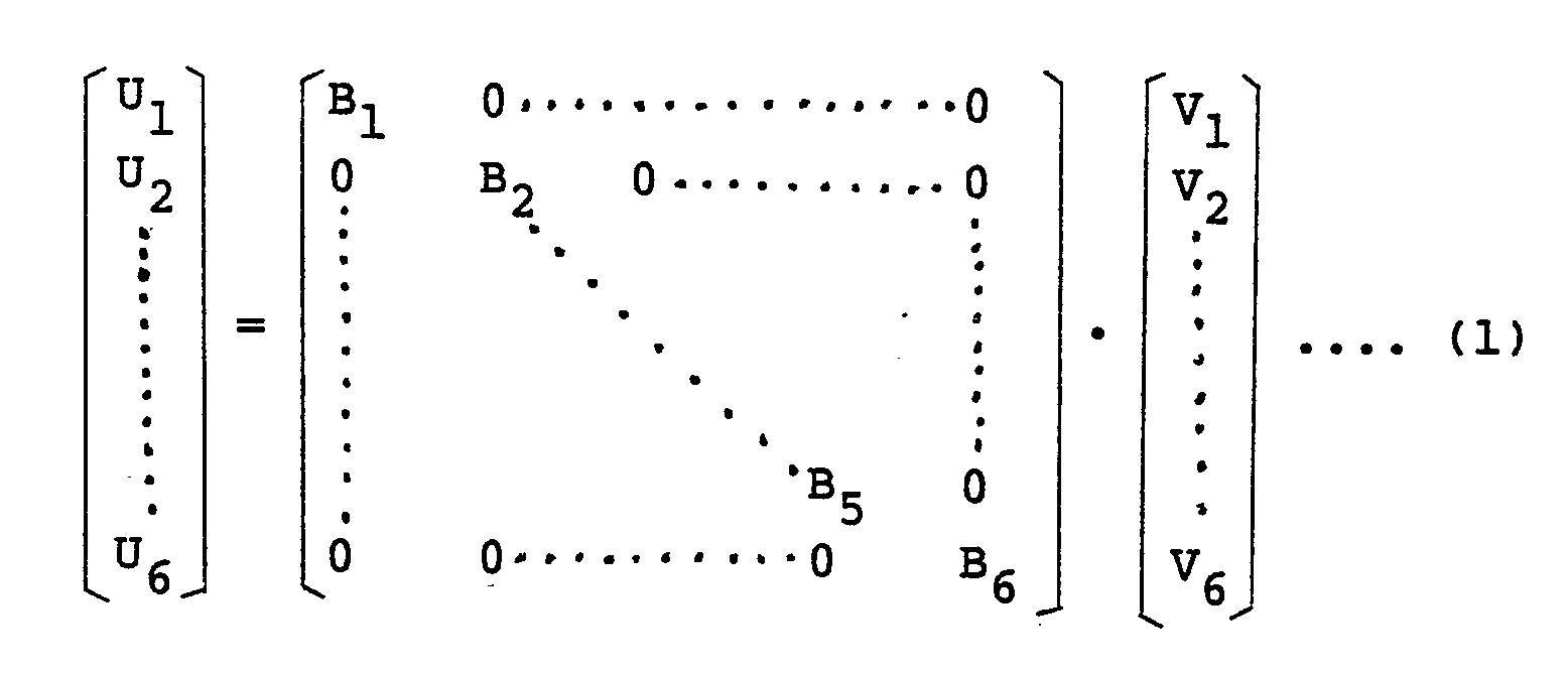
- On the other hand, the relation between the fine motion unit displacements U₁-U₆ and the standard-point displacements x-ϑz can be represented by the following determinant:

- In the determinant (2), the 36 constants C₁₁-C₆₆ can be known by conducting at least 6 times an operation that the respective standard-point displacements x-ϑz are measured upon production of certain displacements in six fine-motion units respectively, the respective standard-point displacements x-ϑz are measured upon production of different displacements in the same fine motion units, and then the resulting equation is then solved. Incidentally, the measurement of these standard-point displacement components x-ϑz can be effected by a sensor provided externally, such as laser displacement sensor.
- The individual matrices of the above determinants (1) and (2) are now abbreviated as follows:


- Then, the determinant (1) and (2) can be expressed as follows:
{Ui} = {Bi}·{Vi} ............... (3)
{Xj} = {Cji}· {Ui) .............. (4) - In the above description, parameters other than those described above may also be expressed in the same manner.
- From the foregoing description, it is only necessary for the characteristic
compensation computing unit 152 to determine a drive voltage {Vi} which can satisfy the following equation. Namely, the drive voltage {Vi} and standard-point displacement (Xj} are determined.
{Xj} = (Dji}·{Vi} ............... (5)
Here, the matrix {Dji} in the equation (5) can be determined by the same method as that employed to determine the matrix {Cji} in the determinant (2). From the equation (5), the drive voltage {Vi} for obtaining the desired standard-point displacement {Xj} can be determined by effecting computation in accordance with the following equation.
{Vi} = {Dji}⁻¹·{Xi} ........... (6) - Consequently, the characteristic
compensation computing unit 152 has as compensation characteristics the inverse characteristics {Dji}⁻¹ of the characteristic matrix {Dji} determined by the above equation (5). Computation is performed in accordance with these inverse characteristics {Dji}⁻¹. - The operation of this displacement controller will next be described. When a target displacement (which will be expressed by (X0j}) of the standard point is set in the target
displacement setting unit 151, this target displacement {X0j} is input to the characteristiccompensation computing unit 152 so that computation is performed in accordance with the above equation (6). This computation apparently results in a solution obtained by substituting the target displacement {X0j} to the standard-point displacement {Xj} in the equation (6). When a drive voltage {Vi} obtained from the above computation is input to afine positioning device 150, a displacement {X0j} occurs at its standard point. - The above operation is now described with reference to the preceding specific embodiment. When x = x, y = 0, z = 0, ϑx = 0, ϑy = 0 and ϑz = 0 are set in the target displacement setting unit in order to produce a desired translational displacement (x, 0, ....,0) at the standard point, these values are input to the characteristic
compensation computing unit 152 to perform computation in accordance with the equation (6), namely,
- The displacement controller shown in Figure 28 has been described above. In the case of ideal characteristics that each fine motion unit is free of any interference unlike the above-mentioned case, the following equation (7) can be derived from the above-described equations (3) and (4):
{Xj} ={Cji}·{Bi}·{Vi} ....... (7)
From a comparison of the equation (7) with the equation (5), the following relation can be derived.
{Dji} = {Cji}·{Bi}
The compensation characteristics {Dji}⁻¹ of the characteristiccompensation computing unit 152 can therefore be obtained as an inverse matrix of the product of the matrices {Bi} and {Cji}. In this case, the fine motion unit displacement {Ui} in the equations (3) and (4) is measured by strain gauges provided with each fine motion unit as shown in Figure 14A or 22. Needless to say, the measurement is also feasible by a displacement sensor other than strain gauge as described before. - Owing to the above construction, the displacement controller of this embodiment can obtain displacements of extremely high accuracy even if it is manufactured with ordinary machining and assembly accuracy.
- Figure 29 is a block diagram of a still further displacement controller for a multi-axis fine positioning device, in which elements of structure identical to their corresponding elements shown in Figure 28 are identified by like reference numerals and letters. Description of these elements is omitted herein.
Numeral 153 indicates an external displacement sensor for detecting each displacement of the standard point of thefine positioning device 150. Theexternal displacement sensor 153 outputs an electrical signal proportional to the displacement detected. A laser displacement sensor is generally used as the external displacement sensor. The laser displacement sensor is provided outside thefine positioning device 150 so as to detect any displacement of its standard point. Designated atnumeral 154 is a subtractor for computing the difference between each detection output {Xj} of theexternal displacement sensor 153 and the target displacement {X0j} set in the targetdisplacement setting unit 151.Numeral 155 indicates a constant generating unit for generating a predetermined constant K₁, whilenumeral 156 designates a multiplying unit for multiplying by the constant K₁ each difference {ΔXj} output from thesubtractor 154. Designated atnumeral 157 is an adding unit for adding together the target displacement {X0j} and each value obtained at the multiplyingunit 156. The displacement controller of this embodiment has such a construction that the so-called feedback control is applied to the construction of the displacement controller shown in Figure 28. The constant K₁ is a feedback gain. - The operation of this displacement controller will next be described. When a target displacement {X0j} of the standard point is set in the
target setting unit 151, a drive voltage {Vi} is output from the characteristiccompensation computing unit 152 like the preceding embodiment so that the standard point of thefine positioning device 150 undergoes a displacement. This displacement {Xj} is detected by theexternal displacement sensor 153, and its difference {Δxj} from the target displacement {X0j}, i.e., {Δxj} = {X0j} - {Xj} is computed at thesubtractor 154. The constant K₁ is multiplied to the thus-computed difference {ΔXj} at the multiplyingunit 156. The product K₁·{Δxj} is then input to the addingunit 157, so that the target displacement {X0j} is adjusted. This adjusted value is then input to the characteristiccompensation computing unit 152 and a new drive voltage {Vi} is then output responsive to the adjusted value, whereby the displacement of the standard point of thefine positioning device 150 is adjusted. - Any deviation of the displacement of the standard point relative to the target displacement {X0j} is gradually corrected by repeating the above-mentioned series of operations. The standard point is stopped when the displacement has coincided with the target displacement.
- In the above description, a proportional control method in which the difference {ΔXj} is multiplied by the feedback gain K₁ is used in order to perform the feedback control effectively. The present invention is however not necessarily limited to the use of such a proportional control method. Needless to say, so-called integral control or differential control may also be used. Therefore, the signal added to the target displacement {X0j} at the adding
unit 157 may be called in more generic term, i.e., "a signal corresponding to the difference {ΔXj}". - In the displacement controller described above, feedback control in which each displacement of the standard point of the fine positioning device is fed back has been applied to the construction of the preceding embodiment. It is hence possible to perform displacement of the standard point with still higher accuracy. If an error is involved for some reasons in the course of obtaining the compensating characteristics {Dji}⁻¹ of the characteristic compensation computing unit or drift characteristics and non-linear characteristics are involved in an electric circuit when the compensation characteristics are composed by the electric circuit, the displacement of the standard point may not be achieved fully with desirable accuracy when the construction of the displacement controller shown in Figure 28 is relied upon. If feedback control is applied as in the present displacement controller, it is however possible to avoid such an error in the compensating characteristics or the influence due to the drift characteristics and non-linear characteristics of the electric circuit, so that highly-accurate positioning can be performed.
- Figure 30 is a block diagram of a still further displacement controller for a multi-axis fine positioning device. Elements of structure identical to their corresponding elements depicted in Figure 29 are identified by like reference numerals, and their description is omitted herein. Designated at numeral 150c is an internal displacement sensor typified by strain gauges (see Figures 14A and 22) cemented on each fine motion unit or a Wheatstone bridge circuit formed of such strain gauges. The
internal displacement sensor 150c output a signal proportional to each displacement {Ui} of each fine motion unit. Displacement indicators of other types may also be used obviously. Numeral 155ʹ indicates a constant generating unit for generating a feedback gain K₂. Designated atnumeral 158 is a displacement transducer for converting a target displacement signal {X0j} into its corresponding fine motion unit displacement signal {U0i}. The present embodiment constitutes a feedback control system as apparent from the drawing. - Here, the
above displacement transducer 158 is described in detail. In order to have thedisplacement transducer 158 produce the displacement {X0j} at the standard point of thefine positioning device 150 as described above when the target displacement signal (X0j} is input, thedisplacement transducer 158 has a function that determines how each fine motion unit should be displaced. In order to exhibit this function, characteristics correlating the standard point displacement {Xj} with the fine motion unit displacement {Ui} are essential. These characteristics are indicated by the displacement interference characteristics {Cji} in the equation (4). Thus, thedisplacement transducer 158 has inverse characteristics {Cji}⁻¹of the displacement interference characteristics {Cji}. By performing computation in accordance the inverse characteristics {Cji}⁻¹, it is possible to output the fine motion unit displacement signal {U0i} for obtaining the target displacement {X0j}. - The operation of the displacement controller will next be described. When the target displacement {X0j} is set in the target
displacement setting unit 151, the fine motion unit displacement signal {X0j} for producing the target displacement {X0j) at the standard point of thefine positioning device 150 is computed at thedisplacement transducer 158 and is then output. When the target displacement {X0j) is input to the characteristiccompensation computing unit 152, its corresponding drive voltage {V0i} is output. This drive voltage {V0i) is converted into the drive voltage{Vi} by way of the addingunit 157. The drive voltage {Vi} is then applied to each fine motion unit of thefine positioning device 150. The parallel and/or radial flexible beams composing each fine motion unit are hence deformed to make the fine motion unit undergo a displacement, whereby the standard point of thefine positioning device 150 is displaced. - When the parallel and/or radial flexible beams are deformed on the other hand, the resistance values of the plural strain gauges cemented there vary responsive to the deformation. These strain gauges are formed into a Wheatstone bride circuit as described above so that a signal proportional to the displacement of the fine motion unit is output from the Wheatstone bridge circuit. Namely, the displacement {Ui} of each fine motion unit is output from the
internal displacement sensor 150c. - At the
subtractor 154, computation is performed to determine the difference {ΔUi} ({ΔUi} = {U0i} - {Ui}) between the target fine motion unit displace ment signal {U0i} output from thedisplacement transducer 158 and the actual fine motion unit displacement {Ui} output from theinternal displacement sensor 150c. At the multiplyingunit 156, the constant K₂ is multiplied to the difference {ΔUi} computed above. The product, K₂·{ΔUi}, is then input to the addingunit 157, whereby the drive voltage {V0i} of the characteristiccompensation computing unit 152 is corrected to output a new drive voltage {Vi} so that the displacement of the standard point of thefine positioning device 150 is corrected. By repeating such correction, the deviation of the standard point from the target displacement {X0j} is corrected gradually. The standard point is stopped when the displacement has coincided with the target displacement. - Similar to the preceding displacement controller, it is possible to use not only proportional control but also integral control or differential control for the feedback control of the displacement controller of this embodiment. It is also similar to the preceding case that capacitance displacement sensors or over-current displacement sensors may also be used as internal displacement sensors instead of strain gauges.
- In the above description, the inverse charac teristics {Cji}⁻¹ of the displacement interference characteristics {Cji} are used by way of example for computation at the
displacement transducer 158. It is a prerequisite for the use of such inverse characteristics to employ an ideal fine motion unit that undergoes displacements in the direction of its main displacement Ui and does not undergo any displacements in other directions as indicated in Figure 27 and by the above equation (1), when the drive voltage {Vi} is applied to a desired fine motion unit. Such a situation however does not exist practically when observed strictly. When the drive voltage {Vi} is applied, it is usual that an interference displacement occurs besides the displacement {Ui} in the main direction of displacements although such an interference displacement is small. If such an interference displacement exists, an issue arises whether the conversion at thedisplacement transducer 158 could be handled solely in relation to the relationship between the fine motion unit displacement {Ui} and the standard point displacement {Xj}, namely, on basis of the inverse characteristics {Cji}⁻¹ alone of the displacement interference characteristics {Cji}. All interference displacement components including the above-mentioned new interference component are however contained in the displacement interference characteristics{Cji} as defined by the equations (2) and (4), provided that {Cji} as defined by the equations (2) and (4) is defined newly as the relation between the fine motion unit displacement {Ui}, which occurs upon application of the drive voltage {Vi} to each of the fine motion units composing an actual fine positioning device, and the standard point displacement {Xj}. Even if one or more interference displacement components are involved in the fine motion unit displacement {Ui}, compensating computation can be performed including all interference components provided that a conversion is effected on the basis of the inverse characteristics {Cji}⁻¹ of {C ji}, which inverse characteristics have been defined newly at thedisplacement transducer 158. Needless to say, it is apparent that {Cji} according to the new definition is not contradictory at all to {Cji) according to the preceding definition. - Owing to the construction described above, the displacement controller of the above embodiment can perform displacements of still higher accuracy. In addition to such an advantage, the displacement controller has remarkable effects as will be described below. Namely, like the displacement controller shown in Figure 29, laser displacement sensors capable of performing detection on the order of micrometers are used as external displacement sensors for detecting displacements of the standard point of a fine positioning device. However, the mounting and adjustment of these laser displacement sensors are extremely cumbersome. A lot of labor and time are therefore required for their mounting and adjustment and moreover, such laser displacement sensors per se are extremely expensive. The above displacement controller does not use such external displacement sensors but makes use of the internal displacement sensors which the fine positioning device itself has. Therefore, the above displacement controller is extremely simple in structure and can be constructed easily at a low price. These advantageous effects have been brought about for the first time, because owing to the use of parallel flexible-beam displacement mechanisms and/or radial flexible-beam displacement mechanisms as fine motion units, the detection of a displacement of one of fine motion units is not affected at all by the drive of the remaining fine motion units and an independent displacement detection is feasible for each fine motion unit.
- Having now fully described the invention, it will be apparent to one of ordinary skill in the art that many changes and modifications can be made without departing from the spirit or scope of the invention as set forth herein.
Claims (60)
a central rigid portion (15);
a first set of outwardly-extending portions (16a,16b) extending symmetrically along a first axis from the central rigid portion (15);
a second set of outwardly-extending portions (17a,17b) extending symmetrically from the central rigid portion (15) along a second axis which is perpendicular to the first axis;
a first set of parallel flexible-beam displacement mechanisms (16Fxa,16Fxb) provided symmetrically to each other with the first set of outwardly-extending portions (16a,16b) respectively to produce translational displacements along the second axis; and
a second set of parallel flexible-beam displacement mechanisms (17Fya,17Fyb) provided symmetrically to each other with the second set of outwardly-extending portions (17a,17b) respectively to produce translational displacements along the first axis.
a rigid support member (35);
a first set of radial flexible-beam displacement mechanisms (36Mya,36Myb) provided symmetrically to each other on the support member (35) to produce angular displacements about a first axis;
a second set of radial flexible-beam displacement mechanisms (36Mxa,36Mxb) provided symmetrically to each other on the support member (35) to produce angular displacements about a second axis which is perpendicular to the first axis; and
a third set of radial flexible-beam displacement mechanisms (41Mza,41Mzb) connected to either one (36Mya, 36Myb) of the sets of radial flexible-beam displacement mechanisms to produce angular displacements about a third axis which is perpendicular to both first and second axes.
a first block (B₁) comprising a central rigid portion (15), a first set of outwardly-extending portions (16a,16b) extending symmetrically along a first axis from the central rigid portion (15) and equipped respectively with first parallel flexible-beam displacement mechanisms (16Fxa,16Fxb) to produce in the first set of outwardly-extending portions (16a,16b) translational displacements along a second axis which is perpendicular to the first axis, and a second set of outwardly-extending portions (17a,17b) extending symmetrically along the second axis from the central rigid portion (15) and equipped respectively with second parallel flexible-beam displacement mechanisms (17Fya,17Fyb) to produce in the second set of outwardly-extending portions (17a,17b) translational displacements along the first axis;
a second block (B₂) comprising a central rigid portion (65) and a set of outwardly-extending portions (66a,66b) extending symmetrically along the second axis from the central rigid portion (65), said outwardly-extending portions (66a,66b) being equipped respectively with parallel flexible-beam displacement mechanisms (66Fza,66Fzb) adapted to produce translational displacement along a third axis, which is perpendicular to both first and second axes, and connected to the second set of outwardly-extending portions (17a,17b) respectively; and a third block (B₃) comprising a rigid ring (35), a set of first radial flexible-beam displacement mechanisms (36Mya,36Myb) provided on the rigid ring (35) and adapted to produce angular displacements about the first axis, a set of second radial flexible-beam displacement mechanisms (36Mxa, 36Mxb) provided on the rigid ring (35) and adapted to produce angular displacements about the second axis, and a set of outwardly-extending portions (37a,37b) extending symmetrically from a central rigid portion (40), which is connected to the central rigid portion (65) of the second block (B₂), and equipped respectively with third radial flexible-beam displace ment mechanisms (41Mza,41Mzb) for producing angular displacements about the third axis.
a central rigid portion (70);
a first set of outwardly-extending portions (71a,71b) extending symmetrically along a first axis from the central rigid portion (70);
a second set of outwardly-extending portions (72a,72b) extending symmetrically from the central rigid portion (70) along a second axis which is perpendicular to the first axis;
a set of radial flexible-beam displacement mechanisms (71Mza,71Mzb) provided symmetrically to each other with the first set of outwardly-extending portions (71a,71b) respectively and adapted to produce angular displacements about a third axis which is perpendicular to both first and second axes, and a set of parallel flexible-beam displacement mechanisms (71Fxa,71Fxb) provided symmetrically to each other with the first set of outwardly-extending portions (71a,71b) respectively and adapted to produce translational displacements along the second axis; and
a set of parallel flexible-beam displacement mechanisms (72Fya,72Fyb) provided symmetrically to each other with the second set of outwardly-extending portions (72a,72b) and adapted to produce translational displacements along the first axis.
a central rigid portion (70);
a first set of outwardly-extending portions (71a,71b) extending symmetrically along a first axis from the central rigid portion (70);
a second set of outwardly-extending portions (72a,72b) extending symmetrically from the central rigid portion (70) along a second axis which is perpendicular to the first axis;
a set of radial flexible-beam displacement mechanisms (71Mza,71Mzb) provided symmetrically to each other with the first set of outwardly-extending portions (71a,71b) respectively and adapted to produce angular displacements about a third axis which is perpendicular to both first and second axes, and a set of parallel flexible-beam displacement mechanisms (71Fxa,71Fxb) provided symmetrically to each other with the first set of outwardly-extending portions (71a,71b) respectively and adapted to produce translational displacements along the second axis;
a set of parallel flexible-beam displacement mechanisms (72Fya,72Fyb) provided symmetrically to each other with the second set of outwardly-extending portions (72a,72b) and adapted to produce translational displacements along the first axis; and
a set of parallel flexible-beam displacement mechanisms (72Fza,72Fzb) provided symmetrically to each other with the second set of outwardly-extending portions (72a,72b) and adapted to produce translational displacements along the third axis.
a rigid support plate (77);
radial flexible-beam displacement mechanisms (78Mya,78Myb) provided on the support plate (77) and adapted to produce angular displacements about a first axis; and
radial flexible-beam displacement mechanisms (78Mxa,78Mxb) provided on the support plate (77) and adapted to produce angular displacements about a second axis which is perpendicular to the first axis.
a central rigid portion (70);
a first set of outwardly-extending portions (71a,71b) extending symmetrically along a first axis from the central rigid portion (70);
a second set of outwardly-extending portions (72a,72b) extending symmetrically from the central rigid portion (70) along a second axis which is perpendicular to the first axis;
a set of radial flexible-beam displacement mechanisms (71Mza,71Mzb) provided symmetrically to each other with the first set of outwardly-extending portions (71a,71b) respectively and adapted to produce angular displacements about a third axis which is perpendicular to both first and second axes, and a set of parallel flexible-beam displacement mechanisms (71Fxa,71Fxb) provided symmetrically to each other with the first set of outwardly-extending portions (71a,71b) respectively and adapted to produce translational displacements along the second axis;
a set of parallel flexible-beam displacement mechanisms (72Fya,72Fyb) provided symmetrically to each other with the second set of outwardly-extending portions (72a,72b) and adapted to produce translational displacements along the first axis, and a set of parallel flexible-beam displacement mechanisms (72Fza, 72Fzb) provided symmetrically to each other with the second set of outwardly-extending portions (72a,72b) and adapted to produce translational displacements along the third axis;
a rigid support plate (77);
radial flexible-beam displacement mechanisms (78Mya,78Myb) provided on the support plate (77) and adapted to produce angular displacements about the fist axis and radial flexible-beam displacement mechanisms (78Mxa,78Mxb) provided on the support plate (77) and adapted to produce angular displacements about the second axis; and
connecting portions (74a,74b,81a,81b) connecting rigid portions (80a,80b) of one set of radial flexible-beam displacement mechanisms (78Mxa,78Mxb), out of both radial flexible beam displacement mechanisms (78Mya, 78Myb,78Mxa,78Mxb) provided on the support plate (77), to one ends of one set of outwardly-extending portions (72a,72b) out of the first and second sets of outwardly-extending portions (71a,71b,72a,72b).
displacement detection means (90a₁-90b₄;135a₁-135b₂;145a₁-145b₂;106a-106b) arranged at predetermined points on the respective planar structural units (29a, 29b;63a,63b);
displacement setting means (95) for setting a target displacement for the fine positioning device and outputting values corresponding to displacements of the respective planar structural units (29a,29b;63a,63b) corresponding to the target displacement; and
control means for controlling voltages to be applied to the respective actuators (26a,26b;60a,60b) so that values obtained by the displacement detection means (90a₁-90b₂;106a-106b,135a₁-135a₂;145a₁-145b₂) and representing the displacements of the respective planar structural units (29a,29b,63a,63b) are coincided with the values output from the displacement setting means (95) and relating to the corresponding displacements.
displacement detection means (90a₁-90b₄; 106a-106b;135a₁-135b₂;145a₁-145b₂) arranged at predetermined points on the respective planar structural units (29a,29b;63a,63b);
displacement setting means (125) for setting a target displacement for the fine positioning device and outputting a value corresponding to the target displacement;
means (131,132,140,141x,141z) for determining, by the displacement detection means (90a₁-90b₂; 106a-106b;135a₁-135a₂;145a₁-145b₂) a first degree of displacement based on a desired displacement form and a second degree of displacement based on a displacement form other than the desired displacement form; and
control means for controlling voltages to be applied to the respective actuator in such a way that the first degree of displacement is coincided with the value output from the displacement setting means and the detection value of the second degree of displacement is controlled at "0".
a target displacement setting unit (151) for outputting a target displacement for each predetermined point on the fine positioning device (150); and
a characteristic compensation computing unit (152) having characteristics opposite to a characteristic matrix, which represents the relation between the drive voltage applied to each fine motion unit and the resulting displacement at the predetermined point, and adapted to compute a drive voltage for each fine motion unit on the basis of the target displacement in accordance with the opposite characteristics.
Applications Claiming Priority (18)
| Application Number | Priority Date | Filing Date | Title |
|---|---|---|---|
| JP210618/86 | 1986-09-09 | ||
| JP21061686A JPS6366613A (en) | 1986-09-09 | 1986-09-09 | Fine positioning device |
| JP210619/86 | 1986-09-09 | ||
| JP21061986A JPS6366615A (en) | 1986-09-09 | 1986-09-09 | Fine positioning device |
| JP61210618A JPH071447B2 (en) | 1986-09-09 | 1986-09-09 | Fine positioning device |
| JP210616/86 | 1986-09-09 | ||
| JP262437/86 | 1986-11-04 | ||
| JP26243786A JPH0652489B2 (en) | 1986-11-04 | 1986-11-04 | Displacement control device for fine positioning device |
| JP61283063A JPH071450B2 (en) | 1986-11-29 | 1986-11-29 | Fine positioning device |
| JP283061/86 | 1986-11-29 | ||
| JP283063/86 | 1986-11-29 | ||
| JP61283061A JPH071448B2 (en) | 1986-11-29 | 1986-11-29 | Fine positioning device |
| JP283062/86 | 1986-11-29 | ||
| JP61283062A JPH071449B2 (en) | 1986-11-29 | 1986-11-29 | Fine positioning device |
| JP76270/87 | 1987-03-31 | ||
| JP76269/87 | 1987-03-31 | ||
| JP7627087A JPH071454B2 (en) | 1986-09-09 | 1987-03-31 | Control device for fine positioning device |
| JP7626987A JPH071453B2 (en) | 1986-09-09 | 1987-03-31 | Control device for fine positioning device |
Publications (3)
| Publication Number | Publication Date |
|---|---|
| EP0264147A2 true EP0264147A2 (en) | 1988-04-20 |
| EP0264147A3 EP0264147A3 (en) | 1988-10-05 |
| EP0264147B1 EP0264147B1 (en) | 1994-01-12 |
Family
ID=27577169
Family Applications (1)
| Application Number | Title | Priority Date | Filing Date |
|---|---|---|---|
| EP87201701A Expired - Lifetime EP0264147B1 (en) | 1986-09-09 | 1987-09-08 | Fine positioning device and displacement controller therefor |
Country Status (3)
| Country | Link |
|---|---|
| US (4) | US4920660A (en) |
| EP (1) | EP0264147B1 (en) |
| DE (1) | DE3788773T2 (en) |
Cited By (6)
| Publication number | Priority date | Publication date | Assignee | Title |
|---|---|---|---|---|
| EP0388898A1 (en) * | 1989-03-21 | 1990-09-26 | BANDEMER, Adalbert | Device for real time regulation of a position |
| WO1994025209A1 (en) * | 1993-04-21 | 1994-11-10 | Mahle Gmbh | Variable mounting of a boring bar on the work spindle of a fineboring machine |
| US6453566B1 (en) | 1999-12-22 | 2002-09-24 | Agie Sa | Movement transmission unit and movement transmission apparatus employing the same |
| DE102007054308A1 (en) | 2007-11-08 | 2009-05-20 | INSTITUT FüR MIKROTECHNIK MAINZ GMBH | Drive device for EDM tools |
| TWI678253B (en) * | 2019-01-10 | 2019-12-01 | 大銀微系統股份有限公司 | Flexible mechanism |
| CN111434969A (en) * | 2019-01-15 | 2020-07-21 | 大银微系统股份有限公司 | Flexible mechanism |
Families Citing this family (30)
| Publication number | Priority date | Publication date | Assignee | Title |
|---|---|---|---|---|
| WO1991001848A1 (en) * | 1989-08-04 | 1991-02-21 | Hatheway Alson E | Precision motion transducer |
| US5187876A (en) * | 1989-08-04 | 1993-02-23 | Hatheway Alson E | Precision motion transducer |
| JP2834832B2 (en) * | 1990-03-15 | 1998-12-14 | 松下電工株式会社 | Attitude control device |
| US5130523A (en) * | 1991-04-22 | 1992-07-14 | Raleigh Freddie L | Coordinate measuring machine with improved flexure and clamp for fiber optic connection |
| US5351412A (en) * | 1991-06-11 | 1994-10-04 | International Business Machines Corporation | Micro positioning device |
| US5360974A (en) * | 1992-10-20 | 1994-11-01 | International Business Machines Corp. | Dual quad flexure scanner |
| US5862003A (en) * | 1995-06-23 | 1999-01-19 | Saif; Muhammad T. A. | Micromotion amplifier |
| RU2130374C1 (en) * | 1998-05-26 | 1999-05-20 | Научно-производственное объединение "Государственный институт прикладной оптики" (Федеральный научно-производственный центр) | Dividing machine for making periodic structures, mainly, ruled diffraction gratings (versions) |
| US6347004B1 (en) | 1998-08-31 | 2002-02-12 | Ricoh Company, Ltd. | Optical scanning apparatus and scanning image forming lens |
| US6183097B1 (en) | 1999-01-12 | 2001-02-06 | Cornell Research Foundation Inc. | Motion amplification based sensors |
| CN1451162A (en) * | 2000-03-30 | 2003-10-22 | 西加特技术有限责任公司 | Microacturator assisted seek and hysteresis correction method and apparatus for a disc drive |
| US6513250B2 (en) * | 2000-07-14 | 2003-02-04 | Rensselaer Polytechnic Institute | Micro positioning device with shared actuators |
| US6606444B2 (en) | 2000-09-28 | 2003-08-12 | Murray R. Harman | Positioning device especially for assembling optical components |
| US20050274219A1 (en) * | 2004-06-01 | 2005-12-15 | Molecular Imprints, Inc. | Method and system to control movement of a body for nano-scale manufacturing |
| JP3792675B2 (en) * | 2003-06-05 | 2006-07-05 | ファナック株式会社 | Fine positioning apparatus and tool correction method |
| US6836968B1 (en) * | 2003-06-25 | 2005-01-04 | Itt Manufacturing Enterprises, Inc. | Precision frictionless flexure based linear translation mechanism insensitive to thermal and vibrational environments |
| US20050170128A1 (en) * | 2004-02-04 | 2005-08-04 | Jean Card And Gift Co., Ltd. | Bag-packed three-dimensional decorative sticker |
| KR100568206B1 (en) * | 2004-02-13 | 2006-04-05 | 삼성전자주식회사 | Stage device |
| US7116463B2 (en) * | 2004-07-15 | 2006-10-03 | Optron Systems, Inc. | High angular deflection micro-mirror system |
| DE102004054359B4 (en) * | 2004-11-10 | 2015-11-05 | Fraunhofer-Gesellschaft zur Förderung der angewandten Forschung e.V. | Device for generating a torsional motion and use thereof |
| KR100687717B1 (en) * | 2004-12-16 | 2007-02-27 | 한국전자통신연구원 | Micro stage with piezoelectric element |
| US7107693B2 (en) * | 2005-01-14 | 2006-09-19 | Illinois Institute Of Technology | Apparatus and method for precise angular positioning |
| JP5197101B2 (en) * | 2008-03-31 | 2013-05-15 | 日本トムソン株式会社 | Movable table device |
| JP6068349B2 (en) * | 2010-10-21 | 2017-01-25 | ソルラブス、 インコーポレイテッドThorlabs, Inc. | Parallelism maintenance device for nanopositioners |
| US9370865B1 (en) * | 2012-05-23 | 2016-06-21 | Western Digital Technologies, Inc. | Flexure based compliance device for use with an assembly device |
| WO2014057843A1 (en) * | 2012-10-11 | 2014-04-17 | 株式会社クリエイティブ テクノロジー | Workpiece holder and method using same for detecting lateral displacement of workpiece |
| CN104016117B (en) * | 2014-05-28 | 2017-01-18 | 京东方科技集团股份有限公司 | Forked plate capable of automatically adjusting position of base plate and adjustment method |
| US10284118B2 (en) * | 2015-02-06 | 2019-05-07 | New Scale Technologies, Inc. | Two-axis angular pointing device and methods of use thereof |
| US12565912B2 (en) * | 2024-03-14 | 2026-03-03 | The Regents Of The University Of Michigan | In-plane inter-stage connection in flexure mechanisms |
| US20250290541A1 (en) * | 2024-03-14 | 2025-09-18 | The Regents Of The University Of Michigan | Out of plane inter-stage connection in flexure mechanisms |
Family Cites Families (16)
| Publication number | Priority date | Publication date | Assignee | Title |
|---|---|---|---|---|
| US3492894A (en) * | 1967-10-02 | 1970-02-03 | Heald Machine Co | Machine tool |
| DE1764325A1 (en) * | 1968-05-17 | 1971-07-01 | Elektromat Veb | Device for aligning and securing epitaxially coated semiconductor material |
| FR2098524A5 (en) * | 1970-07-17 | 1972-03-10 | Thomson Csf | |
| US4019109A (en) * | 1974-05-13 | 1977-04-19 | Hughes Aircraft Company | Alignment system and method with micromovement stage |
| JPS5611515A (en) * | 1979-07-10 | 1981-02-04 | Chiyou Lsi Gijutsu Kenkyu Kumiai | Aligning unit |
| JPS5774601A (en) * | 1980-10-29 | 1982-05-10 | Pentel Kk | Apparatus for fixing finely displacing table |
| US4575942A (en) * | 1982-10-18 | 1986-03-18 | Hitachi, Ltd. | Ultra-precision two-dimensional moving apparatus |
| ATE30960T1 (en) * | 1983-08-09 | 1987-12-15 | Siemens Ag | ADJUSTMENT OR POSITIONING TABLE AND METHOD OF PRODUCTION. |
| US4520570A (en) * | 1983-12-30 | 1985-06-04 | International Business Machines Corporation | Piezoelectric x-y-positioner |
| JPS60150950A (en) * | 1984-01-20 | 1985-08-08 | Hitachi Ltd | Guidance device |
| US4559717A (en) * | 1984-02-21 | 1985-12-24 | The United States Of America As Represented By The Secretary Of Commerce | Flexure hinge |
| DE3411651C1 (en) * | 1984-03-29 | 1989-04-27 | bso Steuerungstechnik GmbH, 6603 Sulzbach | Control arrangement for the synchronization of several drives |
| JPS60259347A (en) * | 1984-06-02 | 1985-12-21 | Canon Inc | Piezoelectric type finely moving element and finely positioning device using thereof |
| GB2185323B (en) * | 1984-10-12 | 1988-01-06 | Vickers Plc | Microscope having an improved stage |
| US4686440A (en) * | 1985-03-11 | 1987-08-11 | Yotaro Hatamura | Fine positioning device |
| US4667415A (en) * | 1985-11-29 | 1987-05-26 | Gca Corporation | Microlithographic reticle positioning system |
-
1987
- 1987-09-08 DE DE3788773T patent/DE3788773T2/en not_active Expired - Fee Related
- 1987-09-08 EP EP87201701A patent/EP0264147B1/en not_active Expired - Lifetime
-
1988
- 1988-09-14 US US07/244,169 patent/US4920660A/en not_active Expired - Lifetime
- 1988-09-14 US US07/244,102 patent/US5005298A/en not_active Expired - Lifetime
- 1988-09-14 US US07/244,101 patent/US4991309A/en not_active Expired - Lifetime
- 1988-09-14 US US07/244,168 patent/US4888878A/en not_active Expired - Lifetime
Cited By (8)
| Publication number | Priority date | Publication date | Assignee | Title |
|---|---|---|---|---|
| EP0388898A1 (en) * | 1989-03-21 | 1990-09-26 | BANDEMER, Adalbert | Device for real time regulation of a position |
| WO1994025209A1 (en) * | 1993-04-21 | 1994-11-10 | Mahle Gmbh | Variable mounting of a boring bar on the work spindle of a fineboring machine |
| US6453566B1 (en) | 1999-12-22 | 2002-09-24 | Agie Sa | Movement transmission unit and movement transmission apparatus employing the same |
| DE102007054308A1 (en) | 2007-11-08 | 2009-05-20 | INSTITUT FüR MIKROTECHNIK MAINZ GMBH | Drive device for EDM tools |
| US8445806B2 (en) | 2007-11-08 | 2013-05-21 | Institut Fur Mikrotechnik Mainz Gmbh | Drive device for erosion tools |
| TWI678253B (en) * | 2019-01-10 | 2019-12-01 | 大銀微系統股份有限公司 | Flexible mechanism |
| CN111434969A (en) * | 2019-01-15 | 2020-07-21 | 大银微系统股份有限公司 | Flexible mechanism |
| CN111434969B (en) * | 2019-01-15 | 2021-10-15 | 大银微系统股份有限公司 | Flexible mechanism |
Also Published As
| Publication number | Publication date |
|---|---|
| US4991309A (en) | 1991-02-12 |
| DE3788773T2 (en) | 1994-08-04 |
| US4920660A (en) | 1990-05-01 |
| US5005298A (en) | 1991-04-09 |
| DE3788773D1 (en) | 1994-02-24 |
| EP0264147A3 (en) | 1988-10-05 |
| EP0264147B1 (en) | 1994-01-12 |
| US4888878A (en) | 1989-12-26 |
Similar Documents
| Publication | Publication Date | Title |
|---|---|---|
| US5005298A (en) | Displacement controller for fine positioning device | |
| EP0195479B1 (en) | Fine positioning device | |
| CN111094922B (en) | Force sensor, torque sensor, force sensing sensor, fingertip force sensor, and method for manufacturing same | |
| JP7755609B2 (en) | Torque sensor using coupled loads and fewer strain gauges | |
| JP2767766B2 (en) | 6-axis force sensor | |
| US6860020B2 (en) | Ultra-precision feeding apparatus | |
| JPS60259347A (en) | Piezoelectric type finely moving element and finely positioning device using thereof | |
| JPH0772026A (en) | Strain element structure and multi-axis force detection sensor using the strain element structure | |
| JPH07109566B2 (en) | Fine positioning device | |
| JPH0555263B2 (en) | ||
| JPS62174811A (en) | Finely positioning device | |
| JPS6157825A (en) | Multiaxial force sensor | |
| JP3130647B2 (en) | Fine movement mechanism | |
| JPS63226707A (en) | Displacement controller for fine positioning device | |
| JPH0351792A (en) | Fine adjustment mechanism | |
| JPH071454B2 (en) | Control device for fine positioning device | |
| JPH07280670A (en) | Drive / detection structure and its control device | |
| JPH071453B2 (en) | Control device for fine positioning device | |
| JPH07319548A (en) | Fine positioning controller | |
| Redmond et al. | Active control of bending vibrations in thick bars using pzt stack actuators | |
| JPH0652489B2 (en) | Displacement control device for fine positioning device | |
| Patrick et al. | Compliant joints with remote centre of compliance for the improvement of the motion accuracy of a gantry stage | |
| JPH0392232A (en) | machine tool table | |
| JPS62187912A (en) | Fine positioning device | |
| JPH0192687A (en) | Fine movement mechanism |
Legal Events
| Date | Code | Title | Description |
|---|---|---|---|
| PUAI | Public reference made under article 153(3) epc to a published international application that has entered the european phase |
Free format text: ORIGINAL CODE: 0009012 |
|
| AK | Designated contracting states |
Kind code of ref document: A2 Designated state(s): DE FR GB NL |
|
| PUAL | Search report despatched |
Free format text: ORIGINAL CODE: 0009013 |
|
| AK | Designated contracting states |
Kind code of ref document: A3 Designated state(s): DE FR GB NL |
|
| 17P | Request for examination filed |
Effective date: 19890404 |
|
| 17Q | First examination report despatched |
Effective date: 19900824 |
|
| GRAA | (expected) grant |
Free format text: ORIGINAL CODE: 0009210 |
|
| AK | Designated contracting states |
Kind code of ref document: B1 Designated state(s): DE FR GB NL |
|
| REF | Corresponds to: |
Ref document number: 3788773 Country of ref document: DE Date of ref document: 19940224 |
|
| ET | Fr: translation filed | ||
| PGFP | Annual fee paid to national office [announced via postgrant information from national office to epo] |
Ref country code: GB Payment date: 19940825 Year of fee payment: 8 |
|
| PGFP | Annual fee paid to national office [announced via postgrant information from national office to epo] |
Ref country code: FR Payment date: 19940929 Year of fee payment: 8 |
|
| PGFP | Annual fee paid to national office [announced via postgrant information from national office to epo] |
Ref country code: NL Payment date: 19940930 Year of fee payment: 8 |
|
| PGFP | Annual fee paid to national office [announced via postgrant information from national office to epo] |
Ref country code: DE Payment date: 19941027 Year of fee payment: 8 |
|
| PLBE | No opposition filed within time limit |
Free format text: ORIGINAL CODE: 0009261 |
|
| STAA | Information on the status of an ep patent application or granted ep patent |
Free format text: STATUS: NO OPPOSITION FILED WITHIN TIME LIMIT |
|
| 26N | No opposition filed | ||
| PG25 | Lapsed in a contracting state [announced via postgrant information from national office to epo] |
Ref country code: GB Effective date: 19950908 |
|
| PG25 | Lapsed in a contracting state [announced via postgrant information from national office to epo] |
Ref country code: NL Effective date: 19960401 |
|
| GBPC | Gb: european patent ceased through non-payment of renewal fee |
Effective date: 19950908 |
|
| PG25 | Lapsed in a contracting state [announced via postgrant information from national office to epo] |
Ref country code: FR Effective date: 19960531 |
|
| PG25 | Lapsed in a contracting state [announced via postgrant information from national office to epo] |
Ref country code: DE Effective date: 19960601 |
|
| NLV4 | Nl: lapsed or anulled due to non-payment of the annual fee |
Effective date: 19960401 |
|
| REG | Reference to a national code |
Ref country code: FR Ref legal event code: ST |