EP0260128A2 - Vakuumsaugvorrichtung - Google Patents
Vakuumsaugvorrichtung Download PDFInfo
- Publication number
- EP0260128A2 EP0260128A2 EP87307981A EP87307981A EP0260128A2 EP 0260128 A2 EP0260128 A2 EP 0260128A2 EP 87307981 A EP87307981 A EP 87307981A EP 87307981 A EP87307981 A EP 87307981A EP 0260128 A2 EP0260128 A2 EP 0260128A2
- Authority
- EP
- European Patent Office
- Prior art keywords
- article
- gripping
- frame
- suction
- hand
- Prior art date
- Legal status (The legal status is an assumption and is not a legal conclusion. Google has not performed a legal analysis and makes no representation as to the accuracy of the status listed.)
- Granted
Links
Images


Classifications
-
- B—PERFORMING OPERATIONS; TRANSPORTING
- B25—HAND TOOLS; PORTABLE POWER-DRIVEN TOOLS; MANIPULATORS
- B25J—MANIPULATORS; CHAMBERS PROVIDED WITH MANIPULATION DEVICES
- B25J15/00—Gripping heads and other end effectors
- B25J15/06—Gripping heads and other end effectors with vacuum or magnetic holding means
- B25J15/0616—Gripping heads and other end effectors with vacuum or magnetic holding means with vacuum
-
- B—PERFORMING OPERATIONS; TRANSPORTING
- B65—CONVEYING; PACKING; STORING; HANDLING THIN OR FILAMENTARY MATERIAL
- B65G—TRANSPORT OR STORAGE DEVICES, e.g. CONVEYORS FOR LOADING OR TIPPING, SHOP CONVEYOR SYSTEMS OR PNEUMATIC TUBE CONVEYORS
- B65G47/00—Article or material-handling devices associated with conveyors; Methods employing such devices
- B65G47/74—Feeding, transfer, or discharging devices of particular kinds or types
- B65G47/90—Devices for picking-up and depositing articles or materials
- B65G47/91—Devices for picking-up and depositing articles or materials incorporating pneumatic, e.g. suction, grippers
-
- B—PERFORMING OPERATIONS; TRANSPORTING
- B65—CONVEYING; PACKING; STORING; HANDLING THIN OR FILAMENTARY MATERIAL
- B65G—TRANSPORT OR STORAGE DEVICES, e.g. CONVEYORS FOR LOADING OR TIPPING, SHOP CONVEYOR SYSTEMS OR PNEUMATIC TUBE CONVEYORS
- B65G49/00—Conveying systems characterised by their application for specified purposes not otherwise provided for
- B65G49/05—Conveying systems characterised by their application for specified purposes not otherwise provided for for fragile or damageable materials or articles
- B65G49/06—Conveying systems characterised by their application for specified purposes not otherwise provided for for fragile or damageable materials or articles for fragile sheets, e.g. glass
- B65G49/061—Lifting, gripping, or carrying means, for one or more sheets forming independent means of transport, e.g. suction cups, transport frames
-
- B—PERFORMING OPERATIONS; TRANSPORTING
- B65—CONVEYING; PACKING; STORING; HANDLING THIN OR FILAMENTARY MATERIAL
- B65G—TRANSPORT OR STORAGE DEVICES, e.g. CONVEYORS FOR LOADING OR TIPPING, SHOP CONVEYOR SYSTEMS OR PNEUMATIC TUBE CONVEYORS
- B65G2249/00—Aspects relating to conveying systems for the manufacture of fragile sheets
- B65G2249/04—Arrangements of vacuum systems or suction cups
-
- Y—GENERAL TAGGING OF NEW TECHNOLOGICAL DEVELOPMENTS; GENERAL TAGGING OF CROSS-SECTIONAL TECHNOLOGIES SPANNING OVER SEVERAL SECTIONS OF THE IPC; TECHNICAL SUBJECTS COVERED BY FORMER USPC CROSS-REFERENCE ART COLLECTIONS [XRACs] AND DIGESTS
- Y10—TECHNICAL SUBJECTS COVERED BY FORMER USPC
- Y10S—TECHNICAL SUBJECTS COVERED BY FORMER USPC CROSS-REFERENCE ART COLLECTIONS [XRACs] AND DIGESTS
- Y10S294/00—Handling: hand and hoist-line implements
- Y10S294/902—Gripping element
Definitions
- the present invention relates to a vacuum suction hand for attachment to an article handling machine, e.g., an arm of a robot.
- the invention relates to a composite hand mechanism of an industrial robot having a mechanism which is attached to the wrist portion of the arm of an industrial robot, manipulator, crane, or the like and performs a composite function such as to sucionally engage and grip an article.
- Hands to hold or grip an article are attached to such devices. These hands are mainly classified into fingerless hands and fingered hands.
- the fingered hand has the ability to grip an article. For example, it has the ability to pinch, sandwich, grasp or the like.
- the fingerless hand has the ability to hold an article.
- Fingerless hands are further classified into the type having an adsorbing ability and the type having a receiving ability or the like. Further, fingerless hands having the said adsorbing ability may be further classified into the vacuum suction type and the magnetic type.
- the adsorption type hand is used in the case of closely piled up articles. Further, in the case of articles which cannot be picked up by magnetism, the vacuum suction type of the adsorption type hand is used.
- the vacuum suction type hand is formed with a vacuum chamber communicating with a vacuum source.
- a vacuum chamber communicating with a vacuum source.
- the upper surface of an article is picked up by the vacuum chamber.
- the hand and industrial robot arm, together with the article the latter may be subjected to predetermined operations such as loading, unloading, or other movements.
- the article After completion of such operations on the article, the article can be easily released by releasing air into the vacuum chamber.
- the suction type hand since only the upper surface of an article is held, there are advantages such that the handling operations can be simplified and the structure of the hand itself is simple. Moreover, the suction force may be relatively large so that even a fairly heavy article can be safely handled.
- the suction force to hold a packaged article is decided by the total area of the holes formed in the punched metal, the surface other than the holes not contributing to the suction force and functioning as what may be called dead space. Since such a dead space exists, a suction surface having a large area is needed to obtain a desired suction force, causing a problem in that the size of the hand must be increased.
- the suction hand has a drawback in that although the holding force in the vertical direction is large, the holding force in the horizontal direction is small. As a result, if a force in the horizontal direction acts on an article, the article may be displaced from the suction pad since the suction force in the horizontal direction is relatively weak. Therefore, although the suction force of the suction type hand is large, in order to more safely perform operations on an article, it is necessary also to provide a mechanical means which can reliably grasp the material.
- Another object of the invention is to provide a composite hand mechanism, i.e. a hand having a mechanism to perform composite functions to suctionally hold and grip an article, having a mechanism such that even if a force in the horizontal direction acts on an article being, the position in which the hand holds the article is not changed, and the suction force is assisted.
- a vacuum suction hand comprising: a frame, arranged to be coupled with an article handling machine, for engaging and holding an article; a recess formed in said frame and communicating with a vacuum source; a porous plate having a plurality of holes covering said recess; a vacuum chamber defined in said frame by said recess and said porous plate; and a sponge layer having continuous air bubbles, attached to the outer surface of said porous plate.
- the invention provides a composite hand mechanism for use in an industrial robot, comprising; a suction mechanism located substantially in the central portion of a frame coupled with an end wrist portion of an arm of the industrial robot and which is arranged to hold the upper surface of an article by a suction force; and gripping mechanisms disposed on both sides of said suction mechanism to grip both side surfaces of the article; wherein said gripping mechanisms include gripping frames which are pivotally attached to said frame by hinge pins and whose gripping width and gripping force can be changed, and gripping plates which are movable in the vertical direction relative to said gripping frame and are arranged to grip the article; and said gripping plate is movable in the vertical direction by a rack and pinion mechanism by a distance which is twice as long as the movement of a member of a driving mechanism.
- the said frame is attached to an arm of an article handling machine, e.g. an arm of a robot, and the sponge material having continuous air bubbles comes into contact with the surface of the article.
- the vacuum chamber is connected to a vacuum source.
- the article is held to the frame by way of the sponge material. In this manner, desired article handling operations can be performed, in particular on a number of articles which are closely piled up.
- a porous plate having a plurality of holes is used.
- the sponge material is attached to the outer surface of the porous plate, even in the case of holding an article packaged in a film, the holes in the porous material are not closed by the film. Therefore, the effective area of suction is equal to the whole area of the said recess, i.e. almost the whole surface of the vacuum chamber, resulting in an increase in suction force.
- the portion which comes into contact with the article consists of sponge material, the article is not damaged. In particular, in the case of handling a plastic film pack age, the plastic film is not damaged.
- the sponge material functions as a filter, it can prevent dust from closing the air suction ports of the vacuum source or vacuum chamber. Particularly, when the vacuum is created by an ejector type vacuum pump, the inflow of the dust can cause a failure of the pump, by choking the orifice. However, since the sponge material functions as a filter, such a problem can be prevented. Further, there is a phenomenon such that if a pin hole exists in the film, the suction force is weakened. By use of this phenomenon, the presence or absence of a pin hole in the packing film can be checked by reference to the ability of the hand to hold the package.
- the frame is attached to an article handling machine or the like, for example the arm of a robot.
- a vacuum source is connected to the suction mechanism.
- a power source or hydraulic pressure source is connected to the drive mechanism of the gripping frame or to the drive mechanism of the rack and pinion mechanism, thereby driving the gripping frame or rack and pinion mechanism.
- the article handling hand is moved over the article and applied to the upper surface of the article.
- the griping plate is set to a predetermined length by the rack and pinion mechanism and the article is gripped from both sides thereof. After the gripping operation of the article is completed in this manner, the arm is driven to move and work the article in accordance with a predetermined procedure.
- Handling operations on a plurality of articles can also be performed as explained above.
- the gripping mechanisms are provided on both sides of the suction mechanism and both sides of the article are gripped during handling, even if a force in the horizontal direction acts on the article, displacement of the article in the horizontal direction is prevented by the griping plates, and at the same time dropping of the article is also prevented. Therefore, the article handling operations are safely performed.
- the gripping mechanisms are provided, even if an accident occurs such as the suction force provided by the vacuum being suddenly lost, dropping of the article can be prevented. Therefore, the article handling operations are safely performed. Further, by gripping the article by the gripping mechanisms, the positions of the suction mechanism and the article are aligned. Thus the composite hand mechanism also functions to adjust the position of the article.
- a punched metal as the porous plate. This is because punched metal has relatively large strength and is cheap.
- a metal mesh can be also used as the porous plate.
- a plate in which a plurality of slits are formed can be also used. It is prefer able to detachably or exchangeably attach the sponge material to the porous plate. Since the sponge material is easily damaged, it is recommended to have many spare sponge materials and to regularly exchange the old damaged sponge material for a new one.
- a composite hand mechanism for use in an industrial robot, it is preferred to drive the gripping frame and the pinion of the rack and pinion mechanism by means of a hydraulic cylinder. Since the suction mechanism needs a vacuum source, when an ejector type vacuum pump is used it is convenient to use a cylinder which is actuated by pneumatic pressure provided by the vacuum pump.
- a frame 1 having a vacuum chamber 2 is supported by a supporting frame 20.
- the plan shape of the frame 1 is substantially rectangular.
- a recess 2a is formed in the lower surface of the frame 1, i.e., in the surface which faces an article.
- the recess 2a partly defines the vacuum chamber 2.
- a sealing pad 3 is received in the peripheral edge portion of the frame 1 around the recess 2a.
- a tapered face 4 is formed on the inside of the sealing pad 3, thereby increasing the hermetical property of the seal surface of the pad and also enabling the frame 1 to be aligned with the article over a wide area.
- a stepped portion 5 is formed in the peripheral edge portion of the recess 2a.
- a porous plate 6 is received in the stepped portion 5.
- the vacuum chamber 2 is formed by the recess 2a and the porous plate 6.
- a punched metal sheet is used as the porous plate 6.
- a sponge material 8 is attached to the outer surface of the porous plate 6.
- the sponge material 8 is attached to the porous plate 6 at the outer peripheral edge by suitable means such as a double coated adhesive tape or the like. It will be appreciated that the sponge material 8 can be detachably attached to the porous plate 6 by other means.
- a tapped hole 9 is formed substantially in the centre of the frame 1.
- a connector 10 is screwed into the hole 9 and is coupled with a vacuum source.
- the frame 1 is connected to an article handling machine (not shown), for example an arm of a robot.
- the supporting frame 20 for coupling the suction hand with the arm comprises a first horizontal frame 21, side plates 22 which support both side edges of the horizontal frame 21, and a second horizontal frame 24 which extends below the horizontal frame 21 so as to be located parallel to the frame 21 at a predetermined distance therefrom. Both ends of the second frame 24 are coupled with the side plates 22 by, e.g., bolts 23.
- Two bushes 25 are attached to the second horizontal frame 24 at a predetermined spacing.
- Bolts 26 are slidably inserted through these bushes and are screwed into brackets 28.
- the brackets 28 are fixed to the frame 1 by bolts 27.
- a coil spring 29 is attached.
- the coil spring 29 acts between a flange portion 30 of the bush 25 and the top of the bracket 28, thereby elastically coupling the horizontal frame 24 with the frame 1 so as not to transfer shocks to the supporting frame 20.
- a flange 31 is fixed substantially in the centre of the horizontal frame 21.
- the supporting frame 20 is attached to an arm (not shown) by way of flange 31.
- the arm is driven to move the supporting frame 20 to a position above the article to be handled. Then, the frame 20 is lowered. Thus, the sealing pad 3 provided on the frame 1 first comes into contact with the upper surface of the article and a suction space is formed.
- the vacuum chamber 2 is communicated with a vacuum source by operating a valve or the like, the pressure in the vacuum chamber is reduced and the packing film of the article is sucked by way of the sponge material 8. Thereafter, the arm is driven and operates to move the article, held to the hand, to a predetermined position. Then, by opening the vacuum chamber 2 to atmosphere, the article is released.
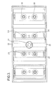
- FIG. 3 An example in which only a single suction hand is provided has been described in the foregoing embodiment, a plurality of suction hands can be provided. Such an example is shown in plan view in Fig. 3.
- four supporting frames 20 and four frames 1 are mounted by a single flange 31.
- the arrangement of the porous plate, sponge material, and the like are the same as in the previous embodiment.
- a suction hand As described in detail above, in a vacuum suction hand according to the invention, since the sponge material is attached to the outer surface of the porous plate forming the vacuum chamber, even if and article to be handled is a packaged article which is wrapped in a plastic film or the like, the film does not close the holes in the porous plate. Therefore the area on which the suction force acts is substantially equal to the area of the vacuum chamber, resulting in an increase in suction force. Thus, a suction hand having a desired suction force can be provided in a compact size. In addition, since it is the sponge material which comes into contact with an article, the article is not damaged. Moreover, since the sponge material also functions as a filter, the problem of choking of the openings in the vacuum source or vacuum chamber or the like does not occur.
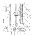
- An article handling hand of the embodiment comprises a frame 101 which is coupled with the arm of a robot or the like, a suction mechanism 120 which is located in substantially the central portion of the frame 101, and gripping mechanisms 140 disposed on both sides of the suction mechanism 120.
- the frame 101 is connected to an article handling machine (not shown), for example the arm of a robot.
- the frame 101 comprises a first horizontal frame 102, side plates 103 which support both sides of the horizontal frame 102, and a second horizontal frame 105 which extends below the horizontal frame 102 so as to be located parallel to the frame 102 at a predetermined distance therefrom.
- Both sides of the second horizontal frame 105 are coupled with the side plates 103 by, e.g., bolts 104.
- Two bushes 106 are attached to the second horizontal frame 105 at a predetermined spacing.
- Bolts 107 are slidably inserted through the bushes 106 and are screwed into brackets 111 which are secured to the suction plate 121 by bolts 108.
- a coil sprin g 109 is attached before each bolt 107 is screwed in.
- the coil spring 109 is disposed between a flange portion 110 of the bush 106 and the bracket 111, thereby elastically coupling the horizontal frame 105 with the suction plate 121 so as not to transfer shocks to the frame 101.
- a flange 112 is fixed substantially in the centre of the horizontal frame 102.
- the frame 101 is coupled with an arm (not shown) of an article handling machine by way of the flange 112.
- the suction plate 121 forms one of the components of the suction mechanism 124, and is rectangular in plan.
- a recess 122 is formed in the lower surface of the suction plate 121, i.e. in the surface which faces an article M.
- the recess 122 partly defines a vacuum chamber 123.
- a sealing pad 124 is attached to the periphery of the recess 122.
- the inside face of the edge of the pad 124 is tapered, thereby enabling the pad 124 to engage the upper surface of an article over a wide range, and increasing its hermetic sealing property.
- a stepped portion 125 is formed in the peripheral edge of the recess 122.
- a porous plate 126 is received in the stepped portion 125.
- the vacuum chamber 123 is defined by the recess 122 and the porous plate 126.
- a plurality of holes 127 are formed in the porous plate 126.
- a punched metal plate is used as the porous plate 126.
- a sponge material 128 having continuous air bubbles is attached to the outer surface of the porous plate 126.
- a connector 129 which is connected to a vacuum source is screw mounted substantially in the centre of the suction plate 121.
- a gripping mechanism 140 comprises a gripping frame 150, a rack and pinion mechanism 160, and a gripping plate 170.
- Two gripping mechanisms 140 are disposed one on each side of the suction mechanism 120.
- the gripping frame 150 is pivotally attached to the side plate 103 by a hinge pin 141.
- the rack and pinion mechanism 160 and gripping plate 170 are attached to the gripping frame 150. Therefore, when the frame 150 swings, the rack and pinion mechanism 160 and gripping plate 170 also swing, so that the article M can be gripped from both sides thereof.
- a coil spring may be used to swing the frame 150 so as to widen the gripping width.
- a piston cylinder unit is used to move the frame 150 so as to grip the aticle.
- a coil spring 142 is attached between the gripping frame 150 and the side plate 103 at a position over the frame 150.
- a piston cylinder uit 143 is disposed between the frame 150 and the side plate 103. The frame 150 is pressed by this piston cylinder unit.
- the rack and pinion mechanism 160 comprises a rack 161 fixed to the frame 150, a rack 171 similarly fixed to the plate 170, a pinion 163 arranged in engagement with the racks 161 and 171, and a piston cylinder unit 164 to drive the pinion 163.
- the gripping plate 170 is disposed so as to be movable in the vertical direction in Fig. 4 relative to the gripping frame 150.
- the rack 171 and plate 170 move by a distance which is twice the movement of the piston of the piston cylinder unit 164, i.e. the movement in the vertical direction of the pinion 163.
- a pad 172 is attached to the plate 170 to enable the plate to come into soft contact with the article M.
- Fig. 4 operates in the following manner.
- the suction mechanism 120 is moved to a position just over the article M.
- the gripping frame 150 is rotated in the direction indicated by arrow A, by the coil spring 142.
- the gripping plate 170 is open downwardly as in the diagram.
- the right and left gripping plates 170 are moved by the rack and pinion mechanisms 160 to positions in which the article can be held and gripped.
- the piston cylinder unit 143 is driven to extend its piston outwardly, whereby the gripping plate 170 is rotated in the direction indicated by arrow B.
- the article M is gripped from both sides therof by the right and left gripping plates 170.
- the position of the centre portion of the article and the central region of the hand become substantially coincident. After such suctioning and gripping of the article the arm is driven to perform the workpiece handling work.
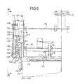
- L-shaped brackets 151 are fixed to the side plate 103 at regular intervals by bolts 152.
- the grippping frame 150 is pivotally attached to the brackets 151 by hinge pins 141 in the horizontal direction.
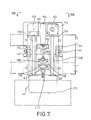
- the piston cylinder unit 164 is attached to the gripping frame 150 by an L-shaped bracket 153. As clearly illustrated in Fig. 7, two shafts 155 are attached by L-shaped metal fittings 154 in the vertical direction. The gripping plate 170 is vertically guided by the shafts 155.
- the rack and pinion mechanism 160 is located in substantially the central portion of the gripping frame 150.
- one rack 161 is fixed to the inside (the right-hand side in Fig. 6) of the frame 150 and the other rack 171 is disposed to face the rack 161 on the inside (the left-hand side in Fig. 6) of the plate 170.
- the pinion 163 is disposed between the racks 161 and 171.
- a rack pin 165 which rotatably axially supports the pinion 163 is disposed in a long hole 167 of a driving mechanism 166.
- the rack pin 165 is urged upwardly by a spring 168, Therefore, if a sudden load was applied to the gripping plate 170, the rack pin 165 moves in the long hole 167, thereby preventing damage to the plate 170.
- the driving mechanism 166 is coupled to a piston rod 169 of the piston cylinder unit 164.
- Two pistons cylinder units 143 are attached to the upper part of the side plate 103.
- a head pin 144 is attached to the end of the piston rod of the unit 143.
- a head receiving member 145 is threadedly attached to the gripping frame 150 at the position where the head pin 144 faces. Therefore, by adjusting the position of the head receiving member 145, the stroke of the piston rod of the unit 143, i.e. the gripping width of the plate 170, can be adjusted.
- two coil springs 142 are attached between the side plate 103 and the frame 150.
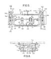
- a single composite hand mechanism is provided.
- a plurality of such hands may be also provided in parallel as shown in Fig. 9.
- four frames, four suction mechanisms, and associated gripping mechanisms are all attached to a single flange 112.
- the gripping mechan isms are provided for each of the frames. Therefore, four articles can be simultaneously handled.
- the positions of the articles can be individually changed to thereby arrange the articles.
- the gripping mechanism to grip both sides of an article are disposed on both sides of the suction mechanism for engaging the upper surface of an article. Therefore, a problem in the suction mechanism is solved in that even if a force in the lateral direction acts on the article, it is not displaced from the suction mechanism.
- the gripping plates of the gripping mechanisms are driven by the rack and pinion mechanism, the driving distance of the pinion is short, so that the whole apparatus can be made of a compact size.
- the gripping plates are movable in the vertical direction, by moving them upwardly, article handling can be provided by only the suction mechanism if desired.
Landscapes
- Engineering & Computer Science (AREA)
- Mechanical Engineering (AREA)
- Robotics (AREA)
- Manipulator (AREA)
Applications Claiming Priority (4)
| Application Number | Priority Date | Filing Date | Title |
|---|---|---|---|
| JP137288/86 | 1986-09-09 | ||
| JP1986137288U JPH074140Y2 (ja) | 1986-09-09 | 1986-09-09 | 真空吸着ハンド |
| JP140590/86 | 1986-09-16 | ||
| JP1986140590U JPH047909Y2 (de) | 1986-09-16 | 1986-09-16 |
Related Child Applications (1)
| Application Number | Title | Priority Date | Filing Date |
|---|---|---|---|
| EP90201735.9 Division-Into | 1987-09-09 |
Publications (3)
| Publication Number | Publication Date |
|---|---|
| EP0260128A2 true EP0260128A2 (de) | 1988-03-16 |
| EP0260128A3 EP0260128A3 (en) | 1988-04-27 |
| EP0260128B1 EP0260128B1 (de) | 1993-05-05 |
Family
ID=26470653
Family Applications (2)
| Application Number | Title | Priority Date | Filing Date |
|---|---|---|---|
| EP90201735A Expired - Lifetime EP0396210B1 (de) | 1986-09-09 | 1987-09-09 | Handmechanismus |
| EP87307981A Expired - Lifetime EP0260128B1 (de) | 1986-09-09 | 1987-09-09 | Vakuumsaugvorrichtung |
Family Applications Before (1)
| Application Number | Title | Priority Date | Filing Date |
|---|---|---|---|
| EP90201735A Expired - Lifetime EP0396210B1 (de) | 1986-09-09 | 1987-09-09 | Handmechanismus |
Country Status (6)
| Country | Link |
|---|---|
| US (1) | US4828304A (de) |
| EP (2) | EP0396210B1 (de) |
| KR (1) | KR950005123B1 (de) |
| AU (2) | AU592667B2 (de) |
| CA (1) | CA1308763C (de) |
| DE (2) | DE3788286T2 (de) |
Cited By (12)
| Publication number | Priority date | Publication date | Assignee | Title |
|---|---|---|---|---|
| DE3817615A1 (de) * | 1988-05-25 | 1989-08-24 | Daimler Benz Ag | Sauggreifer |
| EP0375209A3 (de) * | 1988-12-20 | 1991-09-11 | Texas Instruments Incorporated | Vorrichtung zum Aufheben eines Halbleiterplättchens |
| EP0472354A1 (de) * | 1990-08-14 | 1992-02-26 | Portsmouth Technology Consultants Limited | Vakuum-Greifervorrichtung |
| EP0554592A1 (de) * | 1992-02-04 | 1993-08-11 | House Food Industrial Co., Ltd. | Sauggreifer für Roboter |
| WO1996002444A1 (de) * | 1994-07-15 | 1996-02-01 | Aft Automatisierungs- Und Fördertechnik Gmbh | Lageranlage zum kommissionieren |
| WO1999056518A1 (en) * | 1998-04-28 | 1999-11-04 | Koninklijke Philips Electronics N.V. | Component-handling machine |
| EP1083032A1 (de) * | 1999-09-09 | 2001-03-14 | Tegulas GmbH | Saugkopf |
| GB2378172A (en) * | 2001-06-02 | 2003-02-05 | Tickhill Eng Co Ltd | Gripper in or for a robot |
| WO2004024402A1 (en) * | 2002-09-11 | 2004-03-25 | Automazioni Industriali S.R.L. | Handling unit for cutting machines |
| CN104870341A (zh) * | 2012-10-19 | 2015-08-26 | 陶氏环球技术有限责任公司 | 用于提升和移动可成形的和/或可崩塌的零件的装置、系统和方法 |
| CN105531188A (zh) * | 2013-09-11 | 2016-04-27 | 菲尼克斯电气公司 | 用于处置未封闭折叠箱且用于处置待放置到折叠箱中的件货的处置装置和方法 |
| CN114476743A (zh) * | 2022-01-19 | 2022-05-13 | 业成科技(成都)有限公司 | 片材抓放装置 |
Families Citing this family (62)
| Publication number | Priority date | Publication date | Assignee | Title |
|---|---|---|---|---|
| US5018937A (en) * | 1988-10-05 | 1991-05-28 | Grumman Aerospace Corporation | Shearclip-handling tool |
| US5161847A (en) * | 1989-09-07 | 1992-11-10 | Canon Kabushiki Kaisha | Robot hand |
| EP0535399B1 (de) * | 1991-09-30 | 1995-12-27 | Gisulfo Baccini | Vorrichtung zur Bearbeitung von elektrischen Schaltungen |
| ATE157919T1 (de) * | 1993-03-24 | 1997-09-15 | Hauni Maschinenbau Ag | Robotarm eines flächenportalroboters |
| US5330311A (en) * | 1993-05-14 | 1994-07-19 | Ohmstede-Cawley, Ltd. | Robot means for unloading open boxes |
| US5752729A (en) * | 1993-11-04 | 1998-05-19 | Comalco Aluminium Limited | Vacuum lifting device |
| US5387068A (en) * | 1993-12-06 | 1995-02-07 | Ford Motor Company | Method and system for loading rigid sheet material into shipping containers at a work station and end effector for use therein |
| US5664617A (en) * | 1995-03-24 | 1997-09-09 | Columbia Aluminum Corporation | Sow lifter |
| US5632590A (en) * | 1995-06-30 | 1997-05-27 | Ford Motor Company | Method and system for loading panels into shipping containers at a work station and end effector for use therein |
| EP0978226B1 (de) * | 1997-01-30 | 2001-03-28 | Siemens Aktiengesellschaft | Saugpipette zum greifen von elektrischen bauelementen |
| DE19752896A1 (de) * | 1997-11-28 | 1999-06-02 | Focke & Co | Verfahren und Vorrichtung zum Handhaben von Folien-Weichpackungen |
| US6364387B1 (en) * | 1999-11-10 | 2002-04-02 | Data I/O Corporation | Pick and place system and unit therefor |
| US6264185B1 (en) * | 2000-04-19 | 2001-07-24 | Shoda Iron Works Co., Ltd. | Suction pad |
| US6467824B2 (en) * | 2001-03-13 | 2002-10-22 | Data I/O Corporation | Floating seal pick and place system and unit therefor |
| US6860531B2 (en) * | 2001-12-20 | 2005-03-01 | Abb Inc. | Gripping and vacuum end effector for transferring articles |
| US6988879B2 (en) * | 2002-10-18 | 2006-01-24 | Asm Technology Singapore Pte Ltd | Apparatus and method for reducing substrate warpage |
| CA2560153C (en) * | 2004-03-30 | 2010-09-21 | Jlg Industries, Inc. | Attachment for a telescopic material handler for manipulating a load with five degrees of freedom |
| US20050220599A1 (en) * | 2004-04-02 | 2005-10-06 | Job Matthew A | Clamshell and fork-style material handling apparatus |
| JP2008512321A (ja) * | 2004-09-13 | 2008-04-24 | ミードウエストベコ・コーポレーション | 封筒束および封筒束のパッケージの組立方法 |
| US7789226B2 (en) * | 2004-09-13 | 2010-09-07 | Meadwestvaco Corporation | Packaged banded envelopes |
| US7637711B2 (en) * | 2005-02-08 | 2009-12-29 | Meadwestvaco Corporation | Apparatus with suction head for moving envelopes |
| US7481472B2 (en) * | 2005-03-15 | 2009-01-27 | Sage Automation, Inc. | Layer picking end effector system, apparatus and method |
| DE102006022278A1 (de) * | 2006-05-11 | 2007-11-15 | Deutsche Post Ag | Greifsystem für gestapeltes Stückgut |
| US7409812B2 (en) * | 2006-06-29 | 2008-08-12 | Smart Motion Robotics, Inc. | Robotic packaging device and method |
| US20080187428A1 (en) * | 2007-02-02 | 2008-08-07 | Prototier-1 Inc. | Lift mechanism for a vacuum system |
| US8414042B2 (en) * | 2007-10-15 | 2013-04-09 | Delaware Capital Formation, Inc. | Articulating package palletizing system |
| DE102009011301B4 (de) * | 2009-03-02 | 2020-11-26 | Kuka Roboter Gmbh | Verfahren und Greifer zur Handhabung eines Gebindes mittels eines Manipulators |
| EP2236252B1 (de) * | 2009-03-30 | 2012-10-31 | Carel Johannes Wilhelm Theodoor van Sorgen | Vorrichtung zum Greifen eines Objekts per Ansaugung |
| US8328252B2 (en) * | 2010-03-31 | 2012-12-11 | G.T. Line S.R.L. | Grip assembly, particularly for suitcases and trunks |
| EP2383081B1 (de) * | 2010-04-29 | 2014-06-04 | Trumpf Sachsen GmbH | Fertigungsverfahren zur Erzeugung eines Handhabungsproduktes |
| US20130015675A1 (en) * | 2011-07-15 | 2013-01-17 | Douglas Pickard | Apparatus, system, and method for layer picking and order fulfillment for items stored in a warehouse |
| DE102011111768A1 (de) | 2011-08-24 | 2013-02-28 | Robert Bosch Gmbh | Bernoulli-Greifer mit vollflächiger Werkstückanlage |
| KR101969839B1 (ko) * | 2012-05-07 | 2019-04-18 | 삼성디스플레이 주식회사 | 패널 이송용 흡착기 |
| JP5961064B2 (ja) * | 2012-07-31 | 2016-08-02 | 三星ダイヤモンド工業株式会社 | 吸着テーブルの製造方法並びに吸着テーブル |
| FR2997031B1 (fr) * | 2012-10-23 | 2016-07-01 | Bel Fromageries | Dispositif de prehension d'au moins un produit deformable. |
| CN103192402B (zh) * | 2013-04-14 | 2014-12-10 | 苏州科技学院 | 一种压电超声振动吸附拾取器 |
| KR20160096075A (ko) * | 2013-12-10 | 2016-08-12 | 엔오케이 가부시키가이샤 | 피복재 및 로봇 파지부의 피복 구조 |
| JP6383537B2 (ja) * | 2013-12-10 | 2018-08-29 | 川崎重工業株式会社 | ロボットハンド、ロボット、およびロボットセル |
| KR101500385B1 (ko) * | 2013-12-31 | 2015-03-09 | 현대자동차 주식회사 | 무빙파트 핸들링 장치 |
| EP3206984B1 (de) * | 2014-10-13 | 2018-08-01 | J. Schmalz GmbH | Batteriegreifer |
| EP3341163B1 (de) | 2015-08-26 | 2023-04-19 | Berkshire Grey Operating Company, Inc. | Systeme und verfahren zur kontakterkennung bei einem gelenkarm |
| US10399236B2 (en) | 2015-09-08 | 2019-09-03 | Berkshire Grey, Inc. | Systems and methods for providing dynamic vacuum pressure in an articulated arm end effector |
| US10625432B2 (en) | 2015-11-13 | 2020-04-21 | Berkshire Grey, Inc. | Processing systems and methods for providing processing of a variety of objects |
| ES2922990T3 (es) * | 2016-01-08 | 2022-09-22 | Berkshire Grey Operating Company Inc | Sistemas de adquisición y movimiento de objetos |
| CN105798939A (zh) * | 2016-04-19 | 2016-07-27 | 中国工程物理研究院激光聚变研究中心 | 大口径光学元件真空抓取系统 |
| CN106185313B (zh) * | 2016-08-30 | 2019-01-25 | 苏州万商集包装设备有限公司 | 夹持机构 |
| WO2018165017A1 (en) | 2017-03-06 | 2018-09-13 | Berkshire Grey, Inc. | Systems and methods for efficiently moving a variety of objects |
| JP6702909B2 (ja) * | 2017-04-12 | 2020-06-03 | ファナック株式会社 | ロボットシステム |
| WO2019028242A1 (en) * | 2017-08-03 | 2019-02-07 | Soft Robotics, Inc. | ROBOTIC PREHENSOR FOR HANDLING CARNEOUS PRODUCTS |
| CA3080961C (en) | 2017-11-07 | 2023-10-03 | Berkshire Grey, Inc. | Systems and methods for providing dynamic vacuum pressure at an end effector using a single vacuum source |
| CN107953357A (zh) * | 2017-12-25 | 2018-04-24 | 无锡特恒科技有限公司 | 一种快速抓取装置 |
| CN112752634B (zh) | 2018-07-27 | 2024-05-24 | 伯克希尔格雷营业股份有限公司 | 用于高效地交换端部执行器工具的系统和方法 |
| US11554505B2 (en) | 2019-08-08 | 2023-01-17 | Berkshire Grey Operating Company, Inc. | Systems and methods for providing, in programmable motion devices, compliant end effectors with noise mitigation |
| JP2023507417A (ja) * | 2019-12-19 | 2023-02-22 | テトラ ラバル ホールディングス アンド ファイナンス エス エイ | グリッパユニット |
| US12157223B2 (en) | 2020-02-05 | 2024-12-03 | Berkshire Grey Operating Company, Inc. | Systems and methods for disrupting resonance in vacuum cup assemblies used with programmable motion devices |
| WO2022020178A1 (en) | 2020-07-22 | 2022-01-27 | Berkshire Grey, Inc. | Systems and methods for object processing using a vacuum gripper that provides object retention by shroud inversion |
| CA3189565A1 (en) | 2020-07-22 | 2022-01-27 | Berkshire Grey Operating Company, Inc. | Systems and methods for object processing using a passively collapsing vacuum gripper |
| CA3201277A1 (en) | 2020-11-19 | 2022-05-27 | Berkshire Grey Orerating Company, Inc. | Systems and methods for object processing using grippers for objects with low pose authority |
| US12304062B2 (en) * | 2021-01-04 | 2025-05-20 | The Boeing Company | Part transfer system |
| CA3248499A1 (en) | 2022-01-21 | 2023-07-27 | Berkshire Grey Operating Company, Inc. | Systems and methods for processing objects with programmable motion devices using yawing motion gripping devices |
| DE102023125261A1 (de) * | 2023-09-19 | 2025-03-20 | Liebherr-Verzahntechnik Gmbh | Greifer zur Demontage eines Batteriedeckels |
| DE202023105487U1 (de) * | 2023-09-20 | 2023-10-10 | Krones Aktiengesellschaft | Greiferkopf mit mehreren Sauggreifern und Hebeanordnung mit einem solchen Greiferkopf |
Family Cites Families (11)
| Publication number | Priority date | Publication date | Assignee | Title |
|---|---|---|---|---|
| US2783078A (en) * | 1952-03-07 | 1957-02-26 | Vacuum Concrete Inc | Handling apparatus |
| US3387718A (en) * | 1966-03-10 | 1968-06-11 | Alvey Conveyor Mfg Company | Pallet loading and unloading apparatus |
| US3651957A (en) * | 1970-03-02 | 1972-03-28 | Motorola Inc | Chip packaging and transporting apparatus |
| LU67379A1 (de) * | 1973-04-06 | 1973-06-18 | ||
| DE2600290A1 (de) * | 1976-01-07 | 1977-07-14 | Seifert & Co Rich | Verfahren und vorrichtung zum greifen eines gegenstandes |
| US4355936A (en) * | 1980-08-28 | 1982-10-26 | Diamond International Corporation | Egg transfer apparatus |
| DE3312483A1 (de) * | 1983-04-07 | 1984-10-11 | Blohm + Voss Ag, 2000 Hamburg | Greifer fuer industrieroboter |
| DD220799A1 (de) * | 1984-01-26 | 1985-04-10 | Smab Forsch Entw Rat | Greiforgan fuer rotationssymmetrische und prismatische teile |
| FR2561564B1 (fr) * | 1984-03-26 | 1987-07-03 | Syspro | Dispositif de prehension par ventouse pneumatique |
| US4627785A (en) * | 1984-05-14 | 1986-12-09 | Monforte Robotics, Inc. | Exchangeable multi-function end effector tools |
| DD224801B1 (de) * | 1984-06-21 | 1988-03-23 | Bmk Sued Kb Ipro Dresden Veb | Saugkopf fuer bohrmanipulator |
-
1987
- 1987-09-04 US US07/092,973 patent/US4828304A/en not_active Expired - Fee Related
- 1987-09-08 CA CA000546295A patent/CA1308763C/en not_active Expired - Lifetime
- 1987-09-09 EP EP90201735A patent/EP0396210B1/de not_active Expired - Lifetime
- 1987-09-09 AU AU78190/87A patent/AU592667B2/en not_active Ceased
- 1987-09-09 EP EP87307981A patent/EP0260128B1/de not_active Expired - Lifetime
- 1987-09-09 KR KR1019870009939A patent/KR950005123B1/ko not_active Expired - Fee Related
- 1987-09-09 DE DE90201735T patent/DE3788286T2/de not_active Expired - Fee Related
- 1987-09-09 DE DE8787307981T patent/DE3785712T2/de not_active Expired - Fee Related
-
1989
- 1989-11-08 AU AU44473/89A patent/AU612527B2/en not_active Ceased
Cited By (16)
| Publication number | Priority date | Publication date | Assignee | Title |
|---|---|---|---|---|
| DE3817615A1 (de) * | 1988-05-25 | 1989-08-24 | Daimler Benz Ag | Sauggreifer |
| EP0375209A3 (de) * | 1988-12-20 | 1991-09-11 | Texas Instruments Incorporated | Vorrichtung zum Aufheben eines Halbleiterplättchens |
| EP0472354A1 (de) * | 1990-08-14 | 1992-02-26 | Portsmouth Technology Consultants Limited | Vakuum-Greifervorrichtung |
| EP0554592A1 (de) * | 1992-02-04 | 1993-08-11 | House Food Industrial Co., Ltd. | Sauggreifer für Roboter |
| US5388879A (en) * | 1992-02-04 | 1995-02-14 | House Food Industrial Co., Ltd. | Suction type robot hand |
| WO1996002444A1 (de) * | 1994-07-15 | 1996-02-01 | Aft Automatisierungs- Und Fördertechnik Gmbh | Lageranlage zum kommissionieren |
| WO1999056518A1 (en) * | 1998-04-28 | 1999-11-04 | Koninklijke Philips Electronics N.V. | Component-handling machine |
| EP1083032A1 (de) * | 1999-09-09 | 2001-03-14 | Tegulas GmbH | Saugkopf |
| GB2378172A (en) * | 2001-06-02 | 2003-02-05 | Tickhill Eng Co Ltd | Gripper in or for a robot |
| WO2004024402A1 (en) * | 2002-09-11 | 2004-03-25 | Automazioni Industriali S.R.L. | Handling unit for cutting machines |
| CN104870341A (zh) * | 2012-10-19 | 2015-08-26 | 陶氏环球技术有限责任公司 | 用于提升和移动可成形的和/或可崩塌的零件的装置、系统和方法 |
| CN104870341B (zh) * | 2012-10-19 | 2018-02-06 | 陶氏环球技术有限责任公司 | 用于提升和移动可成形的和/或可崩塌的零件的装置、系统和方法 |
| US9908718B2 (en) | 2012-10-19 | 2018-03-06 | Dow Global Technologies Llc | Device, system, and method for lifting and moving formable and/or collapsible parts |
| CN105531188A (zh) * | 2013-09-11 | 2016-04-27 | 菲尼克斯电气公司 | 用于处置未封闭折叠箱且用于处置待放置到折叠箱中的件货的处置装置和方法 |
| CN114476743A (zh) * | 2022-01-19 | 2022-05-13 | 业成科技(成都)有限公司 | 片材抓放装置 |
| CN114476743B (zh) * | 2022-01-19 | 2024-01-30 | 业成科技(成都)有限公司 | 片材抓放装置 |
Also Published As
| Publication number | Publication date |
|---|---|
| EP0396210B1 (de) | 1993-11-24 |
| EP0260128A3 (en) | 1988-04-27 |
| DE3788286D1 (de) | 1994-01-05 |
| CA1308763C (en) | 1992-10-13 |
| US4828304A (en) | 1989-05-09 |
| EP0260128B1 (de) | 1993-05-05 |
| DE3785712D1 (de) | 1993-06-09 |
| AU4447389A (en) | 1990-03-01 |
| EP0396210A2 (de) | 1990-11-07 |
| KR950005123B1 (ko) | 1995-05-18 |
| DE3785712T2 (de) | 1993-08-19 |
| KR880003713A (ko) | 1988-05-28 |
| AU592667B2 (en) | 1990-01-18 |
| EP0396210A3 (en) | 1990-12-12 |
| DE3788286T2 (de) | 1994-03-31 |
| AU612527B2 (en) | 1991-07-11 |
| AU7819087A (en) | 1988-03-17 |
Similar Documents
| Publication | Publication Date | Title |
|---|---|---|
| EP0260128A2 (de) | Vakuumsaugvorrichtung | |
| KR101715155B1 (ko) | 스택 그리퍼 장치 | |
| JPH0743056Y2 (ja) | 荷役機械 | |
| CN107953354A (zh) | 一种具有柔性夹持固定功能的机器人手爪夹具 | |
| CN212686874U (zh) | 一种夹取机构 | |
| CN213264668U (zh) | 一种装箱码垛自动生产线及其多功能夹具 | |
| CN114671104A (zh) | 拆垛剪打包带机构以及取料装置 | |
| CN209740224U (zh) | 一种袋式物品的抓手 | |
| CN207724320U (zh) | 一种具有柔性夹持固定功能的机器人手爪夹具 | |
| CN207127907U (zh) | 复合码垛机器人抓手 | |
| CN219620300U (zh) | 码垛机机械手以及码垛机 | |
| JP2000141268A (ja) | マニピュレータ用ハンド装置 | |
| CN219098050U (zh) | 一种码拆垛装置 | |
| JP2003192133A (ja) | ボトルハンドリング装置、ボトルハンドリング方法、パレタイズ装置、デパレタイズ装置、コンビネーションパレタイズ装置 | |
| JP4135530B2 (ja) | 物品移載装置 | |
| JPS61257829A (ja) | 物品パレタイジング用ロボツトシステム | |
| CN106697924A (zh) | 一种多功能物料抓手 | |
| CN216830325U (zh) | 取放料机械手和抛光设备 | |
| CN214493489U (zh) | 夹取及码垛装置、机器人 | |
| CN210389228U (zh) | 自动兼容多类产品搬运的机械手末端执行机构 | |
| JPH047909Y2 (de) | ||
| CN115504240A (zh) | 一种集装箱纸盒装货物卸货末端抓取机构及方法 | |
| JP2901782B2 (ja) | 梱包材料の把持ハンド | |
| JPH074140Y2 (ja) | 真空吸着ハンド | |
| KR19980061504U (ko) | 포장보조장치 |
Legal Events
| Date | Code | Title | Description |
|---|---|---|---|
| PUAI | Public reference made under article 153(3) epc to a published international application that has entered the european phase |
Free format text: ORIGINAL CODE: 0009012 |
|
| PUAL | Search report despatched |
Free format text: ORIGINAL CODE: 0009013 |
|
| AK | Designated contracting states |
Kind code of ref document: A2 Designated state(s): DE FR GB IT NL SE |
|
| AK | Designated contracting states |
Kind code of ref document: A3 Designated state(s): DE FR GB IT NL SE |
|
| 17P | Request for examination filed |
Effective date: 19880620 |
|
| 17Q | First examination report despatched |
Effective date: 19890907 |
|
| GRAA | (expected) grant |
Free format text: ORIGINAL CODE: 0009210 |
|
| AK | Designated contracting states |
Kind code of ref document: B1 Designated state(s): DE FR GB IT NL SE |
|
| XX | Miscellaneous (additional remarks) |
Free format text: TEILANMELDUNG 90201735.9 EINGEREICHT AM 09/09/87. |
|
| ITF | It: translation for a ep patent filed | ||
| REF | Corresponds to: |
Ref document number: 3785712 Country of ref document: DE Date of ref document: 19930609 |
|
| ET | Fr: translation filed | ||
| PLBE | No opposition filed within time limit |
Free format text: ORIGINAL CODE: 0009261 |
|
| STAA | Information on the status of an ep patent application or granted ep patent |
Free format text: STATUS: NO OPPOSITION FILED WITHIN TIME LIMIT |
|
| 26N | No opposition filed | ||
| ITTA | It: last paid annual fee | ||
| EAL | Se: european patent in force in sweden |
Ref document number: 87307981.8 |
|
| PGFP | Annual fee paid to national office [announced via postgrant information from national office to epo] |
Ref country code: GB Payment date: 19970724 Year of fee payment: 11 |
|
| PGFP | Annual fee paid to national office [announced via postgrant information from national office to epo] |
Ref country code: SE Payment date: 19970807 Year of fee payment: 11 |
|
| PGFP | Annual fee paid to national office [announced via postgrant information from national office to epo] |
Ref country code: FR Payment date: 19970818 Year of fee payment: 11 |
|
| PGFP | Annual fee paid to national office [announced via postgrant information from national office to epo] |
Ref country code: NL Payment date: 19970930 Year of fee payment: 11 Ref country code: DE Payment date: 19970930 Year of fee payment: 11 |
|
| PG25 | Lapsed in a contracting state [announced via postgrant information from national office to epo] |
Ref country code: GB Free format text: LAPSE BECAUSE OF NON-PAYMENT OF DUE FEES Effective date: 19980909 |
|
| PG25 | Lapsed in a contracting state [announced via postgrant information from national office to epo] |
Ref country code: SE Free format text: LAPSE BECAUSE OF NON-PAYMENT OF DUE FEES Effective date: 19980910 |
|
| PG25 | Lapsed in a contracting state [announced via postgrant information from national office to epo] |
Ref country code: NL Free format text: LAPSE BECAUSE OF NON-PAYMENT OF DUE FEES Effective date: 19990401 |
|
| GBPC | Gb: european patent ceased through non-payment of renewal fee |
Effective date: 19980909 |
|
| EUG | Se: european patent has lapsed |
Ref document number: 87307981.8 |
|
| PG25 | Lapsed in a contracting state [announced via postgrant information from national office to epo] |
Ref country code: FR Free format text: LAPSE BECAUSE OF NON-PAYMENT OF DUE FEES Effective date: 19990531 |
|
| NLV4 | Nl: lapsed or anulled due to non-payment of the annual fee |
Effective date: 19990401 |
|
| PG25 | Lapsed in a contracting state [announced via postgrant information from national office to epo] |
Ref country code: DE Free format text: LAPSE BECAUSE OF NON-PAYMENT OF DUE FEES Effective date: 19990701 |
|
| REG | Reference to a national code |
Ref country code: FR Ref legal event code: ST |
|
| PG25 | Lapsed in a contracting state [announced via postgrant information from national office to epo] |
Ref country code: IT Free format text: LAPSE BECAUSE OF NON-PAYMENT OF DUE FEES;WARNING: LAPSES OF ITALIAN PATENTS WITH EFFECTIVE DATE BEFORE 2007 MAY HAVE OCCURRED AT ANY TIME BEFORE 2007. THE CORRECT EFFECTIVE DATE MAY BE DIFFERENT FROM THE ONE RECORDED. Effective date: 20050909 |