EP0258809A2 - Verfahren und Einrichtung zum Verteilen und Zuführen von Objekten - Google Patents
Verfahren und Einrichtung zum Verteilen und Zuführen von Objekten Download PDFInfo
- Publication number
- EP0258809A2 EP0258809A2 EP87112401A EP87112401A EP0258809A2 EP 0258809 A2 EP0258809 A2 EP 0258809A2 EP 87112401 A EP87112401 A EP 87112401A EP 87112401 A EP87112401 A EP 87112401A EP 0258809 A2 EP0258809 A2 EP 0258809A2
- Authority
- EP
- European Patent Office
- Prior art keywords
- objects
- conveyors
- conveying
- curved
- distributing
- Prior art date
- Legal status (The legal status is an assumption and is not a legal conclusion. Google has not performed a legal analysis and makes no representation as to the accuracy of the status listed.)
- Granted
Links
- 238000000034 method Methods 0.000 title claims abstract description 37
- 239000013013 elastic material Substances 0.000 claims description 2
- 229920003002 synthetic resin Polymers 0.000 claims description 2
- 239000000057 synthetic resin Substances 0.000 claims description 2
- 239000007779 soft material Substances 0.000 claims 1
- 239000000463 material Substances 0.000 description 6
- 230000007246 mechanism Effects 0.000 description 5
- 238000005096 rolling process Methods 0.000 description 4
- 235000012055 fruits and vegetables Nutrition 0.000 description 3
- 230000001788 irregular Effects 0.000 description 2
- 230000000284 resting effect Effects 0.000 description 2
- 238000011144 upstream manufacturing Methods 0.000 description 2
- 239000007767 bonding agent Substances 0.000 description 1
- 230000008021 deposition Effects 0.000 description 1
- 238000011143 downstream manufacturing Methods 0.000 description 1
- 239000000428 dust Substances 0.000 description 1
- 235000013399 edible fruits Nutrition 0.000 description 1
- 239000011521 glass Substances 0.000 description 1
- 239000002184 metal Substances 0.000 description 1
- 229920005989 resin Polymers 0.000 description 1
- 239000011347 resin Substances 0.000 description 1
Images


Classifications
-
- B—PERFORMING OPERATIONS; TRANSPORTING
- B65—CONVEYING; PACKING; STORING; HANDLING THIN OR FILAMENTARY MATERIAL
- B65G—TRANSPORT OR STORAGE DEVICES, e.g. CONVEYORS FOR LOADING OR TIPPING, SHOP CONVEYOR SYSTEMS OR PNEUMATIC TUBE CONVEYORS
- B65G47/00—Article or material-handling devices associated with conveyors; Methods employing such devices
- B65G47/22—Devices influencing the relative position or the attitude of articles during transit by conveyors
- B65G47/26—Devices influencing the relative position or the attitude of articles during transit by conveyors arranging the articles, e.g. varying spacing between individual articles
- B65G47/30—Devices influencing the relative position or the attitude of articles during transit by conveyors arranging the articles, e.g. varying spacing between individual articles during transit by a series of conveyors
-
- B—PERFORMING OPERATIONS; TRANSPORTING
- B65—CONVEYING; PACKING; STORING; HANDLING THIN OR FILAMENTARY MATERIAL
- B65G—TRANSPORT OR STORAGE DEVICES, e.g. CONVEYORS FOR LOADING OR TIPPING, SHOP CONVEYOR SYSTEMS OR PNEUMATIC TUBE CONVEYORS
- B65G47/00—Article or material-handling devices associated with conveyors; Methods employing such devices
- B65G47/52—Devices for transferring articles or materials between conveyors i.e. discharging or feeding devices
- B65G47/68—Devices for transferring articles or materials between conveyors i.e. discharging or feeding devices adapted to receive articles arriving in one layer from one conveyor lane and to transfer them in individual layers to more than one conveyor lane or to one broader conveyor lane, or vice versa, e.g. combining the flows of articles conveyed by more than one conveyor
- B65G47/71—Devices for transferring articles or materials between conveyors i.e. discharging or feeding devices adapted to receive articles arriving in one layer from one conveyor lane and to transfer them in individual layers to more than one conveyor lane or to one broader conveyor lane, or vice versa, e.g. combining the flows of articles conveyed by more than one conveyor the articles being discharged or distributed to several distinct separate conveyors or to a broader conveyor lane
-
- B—PERFORMING OPERATIONS; TRANSPORTING
- B65—CONVEYING; PACKING; STORING; HANDLING THIN OR FILAMENTARY MATERIAL
- B65G—TRANSPORT OR STORAGE DEVICES, e.g. CONVEYORS FOR LOADING OR TIPPING, SHOP CONVEYOR SYSTEMS OR PNEUMATIC TUBE CONVEYORS
- B65G17/00—Conveyors having an endless traction element, e.g. a chain, transmitting movement to a continuous or substantially-continuous load-carrying surface or to a series of individual load-carriers; Endless-chain conveyors in which the chains form the load-carrying surface
- B65G17/30—Details; Auxiliary devices
- B65G17/32—Individual load-carriers
- B65G17/34—Individual load-carriers having flat surfaces, e.g. platforms, grids, forks
-
- B—PERFORMING OPERATIONS; TRANSPORTING
- B65—CONVEYING; PACKING; STORING; HANDLING THIN OR FILAMENTARY MATERIAL
- B65G—TRANSPORT OR STORAGE DEVICES, e.g. CONVEYORS FOR LOADING OR TIPPING, SHOP CONVEYOR SYSTEMS OR PNEUMATIC TUBE CONVEYORS
- B65G21/00—Supporting or protective framework or housings for endless load-carriers or traction elements of belt or chain conveyors
- B65G21/02—Supporting or protective framework or housings for endless load-carriers or traction elements of belt or chain conveyors consisting essentially of struts, ties, or like structural elements
-
- B—PERFORMING OPERATIONS; TRANSPORTING
- B65—CONVEYING; PACKING; STORING; HANDLING THIN OR FILAMENTARY MATERIAL
- B65G—TRANSPORT OR STORAGE DEVICES, e.g. CONVEYORS FOR LOADING OR TIPPING, SHOP CONVEYOR SYSTEMS OR PNEUMATIC TUBE CONVEYORS
- B65G2201/00—Indexing codes relating to handling devices, e.g. conveyors, characterised by the type of product or load being conveyed or handled
- B65G2201/02—Articles
- B65G2201/0202—Agricultural and processed food products
- B65G2201/0211—Fruits and vegetables
Definitions
- the present invention relates to an object distributing and supplying method and apparatus, particularly a method and an apparatus for distributing and conveying a number of objects from various types of conveyors to a plurality of lines, and conveying elements.
- feed mechanisms which comprise a divergent roller conveyor having a large width corresponding to that of the line of many sorting conveyors so as to distribute and supply the objects in uniform rows onto the sorting conveyors equally spaced between them and installed in parallel with each other (for example, as described in the Japanese Utility Model Publication No. Sho 56-47147).
- connection conveyors the conventional feed mechanisms present the disadvantages that although they are designed on the assumption that objects will roll in the desired direction by the aid of their rotations in the course of their travel from the upstream line (the preceding process line) to the downstream apparatuses (hereinafter referred to as "connection conveyors"), the objects may not be uniformly distributed onto three or more connection conveyors due to their different forms and sizes which do not cause the objects to roll properly in the desired direction, but in random directions, and that much more objects may be distributed (conveyed) onto the connection conveyors in the central part of the conveying line than those on the right and left sides of the line.
- top plate chain conveyors using flat plates or top plates as conveying paths have been used to carry objects such as bottles and cans.
- the conventional top plate chain conveyors which comprise a flat plate of metal or resin, and guide rails at both sides of the conveying path on which the top plate runs, are suitable to convey the regularly-formed objects such as glass bottles and metallic cans which have flat bottoms and constant sizes as well as relatively hard surfaces not subject to damage in contact with the side guide rails, while they are not practically applicable to convey the objects such as ball like fruits and vegetables which are soft in surface, liable to roll out and different in size, because these objects are unstable on the conveying paths, apt to be rolled and damaged during the transfer from the preceding process line or during the transportation, and subject to damage in contact with the side rails.
- top plate chain conveyors cannot be supported on their return sides where the chain conveyors are turned over with the top surfaces of the top plates sliding over the return rails.
- the top plate chain conveyors present the demerit that the conveying paths may be stained with dust and oil on the return rails.
- the main object of the present invention is to provide a method and an apparatus which can eliminate various disadvantages presented by the conventional feed mechanisms and which can distribute and supply objects in uniform rows and in a streamline onto the connection conveyors equally spaced and installed in parallel with each other in the downstream process line, in whatever conditions the objects are supplied from the preceding process line (or if the objects are supplied in irregular quantity, or by any of the feed or supply methods).
- Another object of the present invention is to provide a conveying apparatus which can carry soft objects, like balls liable to roll, without rolling them on curved paths.
- Another object of the present invention is to provide conveying elements which permit to carry soft ball-like objects, irregular in form and sizes, in the stable conditions without rolling them, and which can run the conveying surface on the return side without sliding.
- the present invention relates to means for distributing and supplying a number of objects, vulnerable to damage and easy to roll, and supplied at random from the preceding process line, continuously onto many downstream apparatuses (or connection conveyors) equally spaced from each other and installed in parallel with each other.
- the most preferred means for rearranging a number of objects supplied at random in the predetermined number of rows may be constructed so that the conveying apparatus receives objects at its wide receiving comprising starting straight portions of a predetermined number of narrow curved conveyors arranged side by side adjacent to each other, and the curved conveyors each conveying the objects thereon gradually diverge and are increasingly spaced from each other toward a downstream apparatus to connect directly to the downstream apparatus in a almost straight line form so as to supply the objects to the downstream apparatus.
- the conveying apparatus comprises the predetermined number of curved conveyors which have a narrow conveying surface on which at least a row of ball-like objects is carried in the direction of their travel, and which are equipped with conveying elements in a special form to make the conveyors divergently curved.
- the starting end parts of the curved conveyors are connected adjacently and traversely with each other to form a wider part of the conveying surface as the receiving part thereof, where the conveying elements of the conveyors are arranged in parallel rows along the predetermined distance (or length).
- the preceding process line which supplies objects to the receiving part of the conveying apparatus is preferably performed by using a conveying apparatus as wide as the receiving part, and so connected to the receiving part that objects can be uniformly supplied from the preceding process line into the receiving part.
- the curved conveyors have the spacing more widened out divergently and curvedly as it is more distant from the receiving part of the conveying surface, to form a row of conveying paths with the predetermined spacing between each other.
- the terminating end parts of the spaced and curved conveyors are connected directly to the next process line (for example, sorting conveyors) in parallel with each other in the running direction.
- the curved conveyors may be individually driven by the corresponding motors. However, it is preferable that they are driven in interlock by a motor through an intermediate shaft. Alternatively, any other desired driving method may be employed.
- the curved conveyors may comprise any of various chains, or preferably a chain such as the known Side Bow Roller Chain (the brand name of chains by Yamahisa) or Curved Chain (the brand name of chains by Tsubakimoto), which has the same principal sizes as the JIS roller chains as well as a flexibility and side bends (in the form of an arc) with a special clearance between links, and conveying elements according to the present invention.
- a chain such as the known Side Bow Roller Chain (the brand name of chains by Yamahisa) or Curved Chain (the brand name of chains by Tsubakimoto), which has the same principal sizes as the JIS roller chains as well as a flexibility and side bends (in the form of an arc) with a special clearance between links, and conveying elements according to the present invention.
- Each of the conveying elements has a conveying surface which has a central concave part and two right and left convex side parts, and two guide support parts which extend vertically down from the conveying surface of the element and are folded outward at the lower ends respectively so that a pin link of the chain can be fitted between the guide support parts.
- Two guide rails are fitted in the spaces defined by the right and left concave guide support parts of the conveying elements respectively so that the guide rails support the conveying elements horizontally and that the concave guide support parts of the conveying elements are slided on the guide rails.
- the guide rails form a moderately curved conveying path extending from the starting end parts to the terminating end parts of the conveyors respectively.
- the narrow conveying elements are arranged so that they can be run along the curved conveying path formed by the guide rails.
- the guide rails are formed by simple round or square bar members so that they can be formed very easily in the desired curved lines.
- the combined mechanism of the chain and the conveying elements may be constructed by any assembling method, for example, using rivets and screws, elastic fasteners of plastic material, or any bonding agent.
- each conveying element has two guide support parts on both lower sides of the elements as described above, the conveying elements of the conveyor according to the present invention are reversely hung by the guide rails with the conveying surface not in contact with the conveyor frames nor the guide rails, while they are running on the return side (or lower return way) of the conveyor.
- the conveying surfaces of the conveying elements may be covered with a cushion material, or coated with elastic or flexible materials like fins, or artificial lawn or fur planted so as to carry soft and rollable objects in the stable conditions.
- a conveyor frame is constructed by 4 guide rails, or 2 upper rails and 2 lower rails, connected with each other at several points and combined with the guide support parts of the conveying elements.
- the conveying surfaces of the conveying elements according to the present invention are formed in a special concave of which the right and left side parts are higher than the central part, and covered with a cushion material, or coated with elastic or flexible materials like fins, or artificial lawn or fur planted so as to receive soft and rollable objects in the stable conditions.
- the concave form of the conveying surface can prevent ball-like objects from rolling out of the conveying surface, and the projections formed on the conveying surfaces of the conveying elements can serve as a cushion where the soft projections are flexed by the weights of objects, and rest the objects stably.
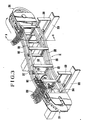
- Figs. 1 and 2 illustrate a preferred embodiment of the present invention together with the downstream and upstream apparatuses as required.
- 1 is a feed conveyor on the preceding process line.
- 2 is a feeder
- 3 is a distributing and supplying apparatus according to the present invention
- 4 is an arraying apparatus which conveys the distributed and supplied objects on arraying and positioning them and adjusting their orientations.
- 5 is a set of conveyors
- 6 is a set of connection conveyors
- 7 is an overflow conveyor which discharge the objects overflowing the arraying apparatus 4.
- the conveying path of the feed conveyor 1 on the preceding process line is as wide as the receiving inlet part of the distributing and supplying apparatus 3, the width of which depends upon the number of rows in which the supplied objects are divided, and that if the conveying path of the feed conveyor 1 is narrower or wider, a feeder 2 is installed between the feed conveyor 1 and the distributing and supplying apparatus 3 to adjust the difference of width between them.
- the feeder 2 may be also used to spread out the superposed objects on the others supplied from the feed conveyor 1 and supply the objects in a layer to the inlet of the distributing and supplying apparatus 3.
- the feeder 2 may be removed.
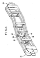
- the distributing and supplying apparatus 3 comprises a number of curved conveyors of narrow width 31 corresponding to the number of connection conveyors 6 (4 conveyors in this embodiment) on the next process line, as shown in Figs. 1 to 7.
- Each of the curved conveyor 31 comprises a curvilinear chain 311 equipped with many conveying elements of narrow width 201 in a special form.
- the receiving part 313 of the distributing and supplying apparatus 3 is composed of the starting end parts 314 of the curved conveyors 31, connected together adjacently and in parallel with each other along a certain length so as to form a wide conveying surface.
- the receiving part 313 is preferably long enough to stabilize the positions of rollable objects transferred from the preceding process line into the receiving part 313.
- the terminating end parts 316 of the curved conveyors 31 are installed in parallel with each other in the running direction, and connected to the arraying apparatus 4, which is connected in turn straightforward to the next process line.
- the curved conveyor 31 comprises a chain 311, preferably a known chain, having a flexibility and side bends, and conveying elements 201.
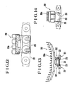
- Each of the conveying elements 201 has two guide support parts 312 which extend vertically downward from the top surface of the element 201 and are folded outward at the lower ends respectively so that a pin link 311a of the chain 311 can be fitted between the guide support parts 312 of the conveying element 201.
- Guide rails 315 are installed in combination with the guide support parts 312 of the conveying elements 201 so that the chain 311 and the conveying elements 201 of a curved conveyor 31 are curvilinearly run.
- the guide rails 315 extend from the starting end part 314 of a curved conveyor 31 to the predetermined position in the terminating end part 316 of the curved conveyor 31 to form a moderately-curved conveying path of the curved conveyor 31.
- the guide rails 315 are installed symmetrically on the upper or conveying path side and the lower or return side of the curved conveyor 31. Therefore, the conveying elements 201 on the return side of the conveyor 31 are hung by the guide support parts 312 of the conveying elements 201 while they are running.
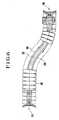
- the conveying paths of the curved conveyors 31 may be installed radially and divergently from the starting end parts 314 to the terminating end parts 316 of the conveyors 31 respectively, as shown in Fig. 1, or otherwise they may be bent to the right (as shown) or left in their courses, as shown in Fig. 21 illustrating another embodiment of the present invention.
- the conveying paths may be installed in the combination of the configurations as shown in Figs. 1 and 21.
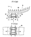
- the width setting members 317 as shown in Figs. 3, 4 and 5 are installed so that the horizontal distance between 2 upper or lower guide rails 315 is constant.
- the connecting members 318 as shown in the figures fix the guide rails 315 on the conveying side and return side of the conveyor 31 vertically.
- the frame of the curved conveyor 31 is formed by the curved guide rails 315 as well as the width setting members 317 and the connecting members 318 mounted on the guide rails 315 at several points.
- the frame of the curved conveyor 31 is fixed on the bases 320 with fixing fittings 319.
- the guide rails 315 of this conveyor 31 serve as both the frame and the chain rails, which it is not required to install separately.
- 304 is a chain tension device installed in the starting end part 314 of the conveyor 31.
- the curved conveyors 31 may be individually driven by motors (not shown), or otherwise driven by a motor in interlock through an intermediate shaft (not shown).
- the curved conveyors 31 receive together the soft and rollable objects supplied from the preceding process line, divide them in rows, and convey them on the moderately curved paths respectively to the predetermined downstream position by widening out the spacing between the rows of objects.
- FIGs. 8 to 18 show several embodiments of conveying element according to the present invention.
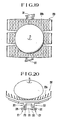
- a conveying element 201 has a top surface formed in a special concave where the right and left sides are higher than the central part.
- the top surface of the conveying element 201 may be provided with soft projections 201a of synthetic resin such as soft PVC, elastic material or flexible material like fins, needles or rods, inclined at a certain angle relative to the conveying top surface of the element 201.
- Figs. 3, 8 and 12 show projections 201a like fins.
- Figs. 9 and 14 show projections 201a like needles or rods.
- the chain 311 is generally known and has side bends and a flexibility.
- Figs. 10 to 12 show the assembly of a conveying element 201 and the chain 311.
- the chain mounting part of the conveying element 201 is designed so that the link plates 321 of the chain 311 are fitted between the lower parts of the conveying element 201.
- the chain mounting part of the conveying element 201 is formed by two guide support parts 312 which extend downward from the top surface of the element 201 and are folded outward at their lower end parts 211 respectively.
- the lower end parts 211 of the guide support parts 312 are provided with pawls 213 mounted inside to fix the link plates 321 respectively. These pawls 213 are elastically engaged with the link plates 321 of the chain 311 respectively, after the link plates 321 have been forcedly fitted between the guide support parts 312 of the conveying element 201.
- the chain 311 may be fitted in the conveying elements 201 by using screws or rivets.
- Figs. 19 and 20 show an object like a ball resting on the top surface of the conveying element 201.
- the soft projections 201a are flexed by the weight of the object and serve as a cushion to rest the object stably.
- the guide rails 315 are fitted in the laterally concave guide support parts 312 of the conveying element 201 respectively to support the conveying element 201 horizontally. These guide rails 315 form a moderately curved conveying path extending from the starting end part 314 to the terminating end part 316 of the curved conveyor 31 so that the guide support parts 312 of the conveying elements 201 are sliding along the conveying path.
- the upper and lower pairs of guide rails are symmetrically installed, the lower or return side of which hangs the running conveying elements 201 at their guide support parts 312 so that the projections 201a on the top surface of the conveying elements 201 are not in contact with the guide rails 315.
- Fig. 15 shows the mounting of the conveying element on the chain.
- Figs. 16 to 18 show another embodiment of the method for mounting the conveying element on the chain.
- the pawls 213 are elastically engaged with the connecting pins 322 of the chain 311 respectively.
- the conveyor 31 thus constructed runs curvilinearly or linearly and carries soft and rollable ball-like objects resting softly and stably on the projections 201a of the conveying elements 201 to the next process line.
- the present invention can receive soft and rollable objects supplied in bulks from the preceding process line as they are, divide them in rows and convey the rows of objects on the moderately curved paths to the downstream line so that the objects are distributed and conveyed smoothly without receiving any external pressure due to any forced rotation, contact or friction.
- the conveying element according to the present invention has two laterally concave type guide support parts which extend downward from the top surface of the conveying element and are folded outward at their lower ends so that the conveying element supports the chain fitted between the vertical parts of the guide support parts and the guide rails fitted in the laterally concave parts of the guide support parts, no chain rail is required, the conveying elements running on the return side of the conveyor 31 are hung by the guide rails, and the top surface of the conveying element which is not in contact with the guide rails and others may be provided with soft and elastic projections formed like fur so that soft and fragile fruits can be conveyed stably on the top surfaces of the conveying elements without giving any damage to them.
- objects can be distributed and supplied on several conveying paths which are installed straight or bent to the right or left by widening out their spacing gradually. Therefore, the facilities using these apparatuses can be freely laid out by utilizing the available space economically and efficiently.
Landscapes
- Engineering & Computer Science (AREA)
- Mechanical Engineering (AREA)
- Branching, Merging, And Special Transfer Between Conveyors (AREA)
- Processing And Handling Of Plastics And Other Materials For Molding In General (AREA)
- Feeding Of Articles To Conveyors (AREA)
Applications Claiming Priority (6)
| Application Number | Priority Date | Filing Date | Title |
|---|---|---|---|
| JP202822/86 | 1986-08-29 | ||
| JP61202822A JPH0780549B2 (ja) | 1986-08-29 | 1986-08-29 | 青果物の曲線搬送コンベア |
| JP1986136492U JPS6342609U (de) | 1986-09-05 | 1986-09-05 | |
| JP136492/86 | 1986-09-05 | ||
| JP1986141554U JPS6348714U (de) | 1986-09-16 | 1986-09-16 | |
| JP141554/86 | 1986-09-16 |
Publications (3)
| Publication Number | Publication Date |
|---|---|
| EP0258809A2 true EP0258809A2 (de) | 1988-03-09 |
| EP0258809A3 EP0258809A3 (en) | 1989-04-19 |
| EP0258809B1 EP0258809B1 (de) | 1992-05-06 |
Family
ID=27317284
Family Applications (1)
| Application Number | Title | Priority Date | Filing Date |
|---|---|---|---|
| EP87112401A Expired - Lifetime EP0258809B1 (de) | 1986-08-29 | 1987-08-26 | Verfahren und Einrichtung zum Verteilen und Zuführen von Objekten |
Country Status (8)
| Country | Link |
|---|---|
| US (1) | US4840265A (de) |
| EP (1) | EP0258809B1 (de) |
| KR (1) | KR930006601B1 (de) |
| CN (1) | CN1016596B (de) |
| AU (1) | AU600508B2 (de) |
| DE (1) | DE3778801D1 (de) |
| ES (1) | ES2030687T3 (de) |
| NZ (1) | NZ221591A (de) |
Cited By (3)
| Publication number | Priority date | Publication date | Assignee | Title |
|---|---|---|---|---|
| WO1989011429A1 (en) * | 1988-05-27 | 1989-11-30 | Systeng Pty. Ltd. | Separator counter |
| WO2013139566A1 (de) * | 2012-03-19 | 2013-09-26 | Wafios Ag | Umformmaschine mit einer transporteinrichtung |
| EP3040297A1 (de) * | 2014-12-22 | 2016-07-06 | Weber Maschinenbau GmbH Breidenbach | Vorrichtung zum bewegen von objekten |
Families Citing this family (20)
| Publication number | Priority date | Publication date | Assignee | Title |
|---|---|---|---|---|
| US5154281A (en) * | 1990-10-03 | 1992-10-13 | Garner Frank D | Automated device for harvesting plants with uniform stem length |
| IT1253225B (it) * | 1991-10-24 | 1995-07-11 | Azionaria Costruzioni Acma Spa | Unita' compattatrice di gruppi di prodotti appiattiti disposti affiancati di taglio |
| US5628393A (en) * | 1995-06-08 | 1997-05-13 | Steeber; Dorian F. | Conveyor apparatus having a nodular conveying surface |
| JP2001225029A (ja) * | 2000-02-18 | 2001-08-21 | Hiroshi Maeda | オンライン内部品質検査用搬送装置 |
| US6601697B2 (en) * | 2001-07-25 | 2003-08-05 | Hartness International | Sloped surface conveyor belt |
| DE102009003475A1 (de) * | 2009-02-12 | 2010-08-19 | Krones Ag | Förderer und Verfahren zum Beschicken einer Weiterverarbeitungseinheit |
| DE102009027280A1 (de) * | 2009-06-29 | 2011-03-03 | Robert Bosch Gmbh | Vorrichtung zum Transportieren von Behältern |
| CN102897514B (zh) * | 2012-10-25 | 2014-10-08 | 浙江大学 | 球形水果成行排列上料装置 |
| CN103693363B (zh) * | 2013-12-20 | 2016-01-27 | 大连佳林设备制造有限公司 | 自动转向定位输送机 |
| CN104003156B (zh) * | 2014-05-22 | 2016-02-10 | 杭州中亚机械股份有限公司 | 一种翻转输送装置 |
| CN105293047B (zh) * | 2015-10-28 | 2017-08-22 | 江苏新美星包装机械股份有限公司 | 由一列分为两列的输送装置中的分瓶送瓶机构 |
| BR102016009259A2 (pt) * | 2016-04-26 | 2017-10-31 | Gsi Brasil Indústria E Comércio De Equipamentos Agropecuarios Ltda. | Modulavel lifting conveyor |
| CN106672538A (zh) * | 2017-03-04 | 2017-05-17 | 中国包装和食品机械有限公司 | 一种水果柔性提升设备 |
| CN107380899A (zh) * | 2017-07-19 | 2017-11-24 | 江苏新美星包装机械股份有限公司 | 理坯机与吹瓶机之间的瓶坯输送装置 |
| CN107628303A (zh) * | 2017-10-30 | 2018-01-26 | 青岛海诺生物工程有限公司 | 装棉球装置 |
| CN109969681A (zh) * | 2017-12-27 | 2019-07-05 | 安徽省安美利特环保材料科技有限公司 | 一种用于制造真空石的输送系统 |
| EP3693299B1 (de) | 2019-02-05 | 2023-08-16 | Illinois Tool Works, Inc. | Vorrichtung zum kontinuierlichen fördern von fördergut und verfahren zum kontinuierlichen fördern von fördergut |
| DE102020126448B4 (de) * | 2020-10-08 | 2022-11-10 | Deutsche Post Ag | Verfahren und Vorrichtung zum Beladen von Behältern mit Packstücken |
| CN115178496B (zh) * | 2022-07-11 | 2024-06-21 | 合肥美亚光电技术股份有限公司 | 输送装置、分选设备 |
| CN116079848A (zh) * | 2023-04-06 | 2023-05-09 | 千年舟新材科技集团股份有限公司 | 刨切机送料系统 |
Family Cites Families (26)
| Publication number | Priority date | Publication date | Assignee | Title |
|---|---|---|---|---|
| US2528114A (en) * | 1946-07-06 | 1950-10-31 | California Packing Corp | Conveying system |
| DE1431667A1 (de) * | 1964-09-10 | 1969-04-30 | Konrad Grebe | Fahrbarer Foerderer |
| US3366220A (en) * | 1965-11-23 | 1968-01-30 | Gen Foods Corp | Method and apparatus for single filing |
| US3521322A (en) * | 1967-03-08 | 1970-07-21 | Nordischer Maschinenbau | Conveyor belt for gripping and carrying fish |
| US3669247A (en) * | 1971-03-17 | 1972-06-13 | Velten & Pulver | Conveyor system and attachments therefor |
| JPS524821A (en) * | 1975-07-01 | 1977-01-14 | Fuji Photo Film Co Ltd | Process for manufacturing composition for thermodevelopable photosensi tive material |
| US3722661A (en) * | 1971-05-19 | 1973-03-27 | R Williams | Article conveyor system |
| US3842968A (en) * | 1973-11-19 | 1974-10-22 | Velten & Pulver | Snap-on attachment |
| IT1013761B (it) * | 1974-06-11 | 1977-03-30 | Valli Roberto | Dispositivo di trasferimento verti cale delle uova per impianti di batterie a piu piani per alleva mento ovaiole allo scopo di con sentire il convogliamento e la raccolta di queste in un unica posizione |
| AU493376B1 (en) * | 1975-05-12 | 1977-11-17 | Baker Perkins Pty. Ltd | Article turning arrangements |
| JPS533583A (en) * | 1976-06-29 | 1978-01-13 | Nakajima Sakao | Photosynthesis utilizying liquid membrane flow on light source surface |
| JPS556739A (en) * | 1978-06-30 | 1980-01-18 | Nippon Telegraph & Telephone | Method of manufacturing cable sheath |
| JPS5546660A (en) * | 1978-09-29 | 1980-04-01 | Fujitsu Ltd | Timing signal extraction circuit device |
| JPS5647147A (en) * | 1979-09-27 | 1981-04-28 | Ricoh Co Ltd | Data transmission system |
| JPS5638024A (en) * | 1980-07-16 | 1981-04-13 | Canon Inc | Photographing control unit |
| JPS5732981A (en) * | 1980-08-07 | 1982-02-22 | Mitsubishi Electric Corp | Heating element for printing |
| JPS5734173A (en) * | 1980-08-09 | 1982-02-24 | Tadashi Takahashi | Aerosol composition |
| FR2524435B1 (fr) * | 1982-04-01 | 1989-03-03 | Gross Maurice | Chaine a forte adherence |
| JPS5928973A (ja) * | 1982-08-07 | 1984-02-15 | 株式会社トツプ | 薬液充填済みの注射筒の製造方法 |
| JPS5928972A (ja) * | 1982-08-10 | 1984-02-15 | 株式会社日本メデイカル・サブライ | 血液浄化用吸着体及びその製造方法 |
| JPH06102488B2 (ja) * | 1985-08-20 | 1994-12-14 | 株式会社マキ製作所 | 青果物の分配供給装置 |
| DE8526919U1 (de) * | 1985-09-20 | 1985-11-14 | Affeldt Verpackungsmaschinen GmbH, 2201 Neuendorf | Verteilerband für Wiege- oder Zählvorrichtungen, insbesondere für Obst, Gemüse und dgl. |
| US5232892A (en) * | 1991-09-03 | 1993-08-03 | Minnesota Mining And Manufacturing Company | Dye receptor sheet for thermal dye transfer imaging |
| JPH05212470A (ja) * | 1992-02-06 | 1993-08-24 | Mitsuboshi Seisakusho:Kk | インプットシャフトとその製造方法 |
| JPH05333986A (ja) * | 1992-05-29 | 1993-12-17 | Nec Eng Ltd | 入力文字表示機能付きキーボード |
| JPH05333987A (ja) * | 1992-05-29 | 1993-12-17 | Matsushita Electric Ind Co Ltd | キーボード装置 |
-
1987
- 1987-08-18 US US07/086,711 patent/US4840265A/en not_active Expired - Lifetime
- 1987-08-19 AU AU77228/87A patent/AU600508B2/en not_active Expired
- 1987-08-26 EP EP87112401A patent/EP0258809B1/de not_active Expired - Lifetime
- 1987-08-26 ES ES198787112401T patent/ES2030687T3/es not_active Expired - Lifetime
- 1987-08-26 DE DE8787112401T patent/DE3778801D1/de not_active Expired - Lifetime
- 1987-08-27 NZ NZ221591A patent/NZ221591A/xx unknown
- 1987-08-28 CN CN87106056A patent/CN1016596B/zh not_active Expired
- 1987-08-29 KR KR1019870009508A patent/KR930006601B1/ko not_active Expired - Lifetime
Cited By (3)
| Publication number | Priority date | Publication date | Assignee | Title |
|---|---|---|---|---|
| WO1989011429A1 (en) * | 1988-05-27 | 1989-11-30 | Systeng Pty. Ltd. | Separator counter |
| WO2013139566A1 (de) * | 2012-03-19 | 2013-09-26 | Wafios Ag | Umformmaschine mit einer transporteinrichtung |
| EP3040297A1 (de) * | 2014-12-22 | 2016-07-06 | Weber Maschinenbau GmbH Breidenbach | Vorrichtung zum bewegen von objekten |
Also Published As
| Publication number | Publication date |
|---|---|
| KR930006601B1 (ko) | 1993-07-21 |
| AU600508B2 (en) | 1990-08-16 |
| ES2030687T3 (es) | 1992-11-16 |
| CN87106056A (zh) | 1988-03-23 |
| AU7722887A (en) | 1988-03-03 |
| KR880002732A (ko) | 1988-05-11 |
| CN1016596B (zh) | 1992-05-13 |
| US4840265A (en) | 1989-06-20 |
| EP0258809B1 (de) | 1992-05-06 |
| DE3778801D1 (de) | 1992-06-11 |
| EP0258809A3 (en) | 1989-04-19 |
| NZ221591A (en) | 1989-03-29 |
Similar Documents
| Publication | Publication Date | Title |
|---|---|---|
| EP0258809B1 (de) | Verfahren und Einrichtung zum Verteilen und Zuführen von Objekten | |
| KR930006602B1 (ko) | 구르기 쉽고 손상되기 쉬운 과일 및 야채와 같은 물품의 분배공급방법 및 장치 | |
| EP0517342B1 (de) | Apparat zum Überführen von Gegenständen wie Eier unter Verwendung einer Bürste | |
| US4351429A (en) | Conveyor with slip cleats | |
| EP0888985A1 (de) | Trennwand zur Montage über einem Band zum Transport von Gegenständen wie Flaschen oder dergleichen | |
| JPH10147425A (ja) | 卵等の実質上円形または楕円形物品の自動分配装置 | |
| US5992615A (en) | Curved conveyor section | |
| US6170637B1 (en) | Article feeding apparatus | |
| US8061511B2 (en) | Conveyor belt guide | |
| US11242207B2 (en) | Multistage conveyor units for separating parcels | |
| US6481567B2 (en) | Conveyor system with intermediate drive and related method | |
| EP0928758A1 (de) | Zuführvorrichtung für Artikel | |
| US4410079A (en) | Egg conveyor turning apparatus | |
| US3752293A (en) | Article grouping system | |
| US3298499A (en) | Conveying and transfer apparatus for eggs | |
| JPS6360811A (ja) | 青果物の曲線搬送コンベア | |
| JPS6366014A (ja) | 青果物の整列供給装置 | |
| JP2935011B2 (ja) | 鶏卵の向きを揃える装置 | |
| JP2613500B2 (ja) | 搬送装置 | |
| JP2572290B2 (ja) | 鶏卵の整列装置 | |
| JPH01209217A (ja) | 物品の整列搬送装置 | |
| US1945324A (en) | Conveyer | |
| US4763774A (en) | Transport device | |
| JP2533123B2 (ja) | 球塊状青果物の整列供給装置 | |
| JPH08157046A (ja) | 長尺野菜の整列定ピッチ供給装置 |
Legal Events
| Date | Code | Title | Description |
|---|---|---|---|
| PUAI | Public reference made under article 153(3) epc to a published international application that has entered the european phase |
Free format text: ORIGINAL CODE: 0009012 |
|
| AK | Designated contracting states |
Kind code of ref document: A2 Designated state(s): DE ES FR GB IT NL |
|
| PUAL | Search report despatched |
Free format text: ORIGINAL CODE: 0009013 |
|
| AK | Designated contracting states |
Kind code of ref document: A3 Designated state(s): DE ES FR GB IT NL |
|
| RHK1 | Main classification (correction) |
Ipc: B65G 47/71 |
|
| 17P | Request for examination filed |
Effective date: 19891012 |
|
| 17Q | First examination report despatched |
Effective date: 19900213 |
|
| GRAA | (expected) grant |
Free format text: ORIGINAL CODE: 0009210 |
|
| AK | Designated contracting states |
Kind code of ref document: B1 Designated state(s): DE ES FR GB IT NL |
|
| ITF | It: translation for a ep patent filed | ||
| REF | Corresponds to: |
Ref document number: 3778801 Country of ref document: DE Date of ref document: 19920611 |
|
| ET | Fr: translation filed | ||
| REG | Reference to a national code |
Ref country code: ES Ref legal event code: FG2A Ref document number: 2030687 Country of ref document: ES Kind code of ref document: T3 |
|
| PLBE | No opposition filed within time limit |
Free format text: ORIGINAL CODE: 0009261 |
|
| STAA | Information on the status of an ep patent application or granted ep patent |
Free format text: STATUS: NO OPPOSITION FILED WITHIN TIME LIMIT |
|
| 26N | No opposition filed | ||
| PGFP | Annual fee paid to national office [announced via postgrant information from national office to epo] |
Ref country code: ES Payment date: 20000804 Year of fee payment: 14 |
|
| PGFP | Annual fee paid to national office [announced via postgrant information from national office to epo] |
Ref country code: GB Payment date: 20000816 Year of fee payment: 14 |
|
| PGFP | Annual fee paid to national office [announced via postgrant information from national office to epo] |
Ref country code: FR Payment date: 20000830 Year of fee payment: 14 |
|
| PGFP | Annual fee paid to national office [announced via postgrant information from national office to epo] |
Ref country code: NL Payment date: 20000831 Year of fee payment: 14 |
|
| PGFP | Annual fee paid to national office [announced via postgrant information from national office to epo] |
Ref country code: DE Payment date: 20001021 Year of fee payment: 14 |
|
| PG25 | Lapsed in a contracting state [announced via postgrant information from national office to epo] |
Ref country code: GB Free format text: LAPSE BECAUSE OF NON-PAYMENT OF DUE FEES Effective date: 20010826 |
|
| PG25 | Lapsed in a contracting state [announced via postgrant information from national office to epo] |
Ref country code: ES Free format text: LAPSE BECAUSE OF NON-PAYMENT OF DUE FEES Effective date: 20010827 |
|
| PG25 | Lapsed in a contracting state [announced via postgrant information from national office to epo] |
Ref country code: NL Free format text: LAPSE BECAUSE OF NON-PAYMENT OF DUE FEES Effective date: 20020301 |
|
| GBPC | Gb: european patent ceased through non-payment of renewal fee |
Effective date: 20010826 |
|
| PG25 | Lapsed in a contracting state [announced via postgrant information from national office to epo] |
Ref country code: FR Free format text: LAPSE BECAUSE OF NON-PAYMENT OF DUE FEES Effective date: 20020430 |
|
| NLV4 | Nl: lapsed or anulled due to non-payment of the annual fee |
Effective date: 20020301 |
|
| PG25 | Lapsed in a contracting state [announced via postgrant information from national office to epo] |
Ref country code: DE Free format text: LAPSE BECAUSE OF NON-PAYMENT OF DUE FEES Effective date: 20020501 |
|
| REG | Reference to a national code |
Ref country code: FR Ref legal event code: ST |
|
| REG | Reference to a national code |
Ref country code: ES Ref legal event code: FD2A Effective date: 20020911 |
|
| PG25 | Lapsed in a contracting state [announced via postgrant information from national office to epo] |
Ref country code: IT Free format text: LAPSE BECAUSE OF NON-PAYMENT OF DUE FEES;WARNING: LAPSES OF ITALIAN PATENTS WITH EFFECTIVE DATE BEFORE 2007 MAY HAVE OCCURRED AT ANY TIME BEFORE 2007. THE CORRECT EFFECTIVE DATE MAY BE DIFFERENT FROM THE ONE RECORDED. Effective date: 20050826 |