EP0256901A1 - Schaltvorrichtung mit symmetrischer Perkussion unter Verwendung eines Sprungwerkes mit Überschreitung eines Totpunktes - Google Patents
Schaltvorrichtung mit symmetrischer Perkussion unter Verwendung eines Sprungwerkes mit Überschreitung eines Totpunktes Download PDFInfo
- Publication number
- EP0256901A1 EP0256901A1 EP87401599A EP87401599A EP0256901A1 EP 0256901 A1 EP0256901 A1 EP 0256901A1 EP 87401599 A EP87401599 A EP 87401599A EP 87401599 A EP87401599 A EP 87401599A EP 0256901 A1 EP0256901 A1 EP 0256901A1
- Authority
- EP
- European Patent Office
- Prior art keywords
- actuator
- spring
- lever
- movable contact
- force
- Prior art date
- Legal status (The legal status is an assumption and is not a legal conclusion. Google has not performed a legal analysis and makes no representation as to the accuracy of the status listed.)
- Granted
Links
- 238000009527 percussion Methods 0.000 title claims abstract description 8
- 230000007935 neutral effect Effects 0.000 claims abstract description 26
- 238000006073 displacement reaction Methods 0.000 claims abstract description 10
- 239000000969 carrier Substances 0.000 claims description 14
- 230000002441 reversible effect Effects 0.000 claims description 6
- 230000003042 antagnostic effect Effects 0.000 claims description 4
- 238000010586 diagram Methods 0.000 description 15
- 230000014509 gene expression Effects 0.000 description 6
- 230000001960 triggered effect Effects 0.000 description 3
- 240000008042 Zea mays Species 0.000 description 2
- 238000012550 audit Methods 0.000 description 2
- 238000001816 cooling Methods 0.000 description 2
- 230000001627 detrimental effect Effects 0.000 description 2
- 230000000694 effects Effects 0.000 description 2
- 238000010438 heat treatment Methods 0.000 description 2
- 206010003830 Automatism Diseases 0.000 description 1
- 101100536354 Drosophila melanogaster tant gene Proteins 0.000 description 1
- 241000287107 Passer Species 0.000 description 1
- 230000001154 acute effect Effects 0.000 description 1
- 230000000712 assembly Effects 0.000 description 1
- 238000000429 assembly Methods 0.000 description 1
- 230000007423 decrease Effects 0.000 description 1
- 238000012423 maintenance Methods 0.000 description 1
- 238000004519 manufacturing process Methods 0.000 description 1
- 238000000034 method Methods 0.000 description 1
- 238000000926 separation method Methods 0.000 description 1
- 230000011664 signaling Effects 0.000 description 1
Images

Classifications
-
- H—ELECTRICITY
- H01—ELECTRIC ELEMENTS
- H01H—ELECTRIC SWITCHES; RELAYS; SELECTORS; EMERGENCY PROTECTIVE DEVICES
- H01H9/00—Details of switching devices, not covered by groups H01H1/00 - H01H7/00
-
- H—ELECTRICITY
- H01—ELECTRIC ELEMENTS
- H01H—ELECTRIC SWITCHES; RELAYS; SELECTORS; EMERGENCY PROTECTIVE DEVICES
- H01H5/00—Snap-action arrangements, i.e. in which during a single opening operation or a single closing operation energy is first stored and then released to produce or assist the contact movement
- H01H5/04—Energy stored by deformation of elastic members
- H01H5/06—Energy stored by deformation of elastic members by compression or extension of coil springs
-
- H—ELECTRICITY
- H01—ELECTRIC ELEMENTS
- H01H—ELECTRIC SWITCHES; RELAYS; SELECTORS; EMERGENCY PROTECTIVE DEVICES
- H01H83/00—Protective switches, e.g. circuit-breaking switches, or protective relays operated by abnormal electrical conditions otherwise than solely by excess current
- H01H83/20—Protective switches, e.g. circuit-breaking switches, or protective relays operated by abnormal electrical conditions otherwise than solely by excess current operated by excess current as well as by some other abnormal electrical condition
- H01H83/22—Protective switches, e.g. circuit-breaking switches, or protective relays operated by abnormal electrical conditions otherwise than solely by excess current operated by excess current as well as by some other abnormal electrical condition the other condition being imbalance of two or more currents or voltages
- H01H83/223—Protective switches, e.g. circuit-breaking switches, or protective relays operated by abnormal electrical conditions otherwise than solely by excess current operated by excess current as well as by some other abnormal electrical condition the other condition being imbalance of two or more currents or voltages with bimetal elements
-
- H—ELECTRICITY
- H01—ELECTRIC ELEMENTS
- H01H—ELECTRIC SWITCHES; RELAYS; SELECTORS; EMERGENCY PROTECTIVE DEVICES
- H01H71/00—Details of the protective switches or relays covered by groups H01H73/00 - H01H83/00
- H01H71/10—Operating or release mechanisms
- H01H2071/109—Operating or release mechanisms with provisions for selecting between automatic or manual reset
-
- H—ELECTRICITY
- H01—ELECTRIC ELEMENTS
- H01H—ELECTRIC SWITCHES; RELAYS; SELECTORS; EMERGENCY PROTECTIVE DEVICES
- H01H5/00—Snap-action arrangements, i.e. in which during a single opening operation or a single closing operation energy is first stored and then released to produce or assist the contact movement
- H01H5/04—Energy stored by deformation of elastic members
- H01H5/06—Energy stored by deformation of elastic members by compression or extension of coil springs
- H01H5/12—Energy stored by deformation of elastic members by compression or extension of coil springs having two or more snap-action motions in succession
Definitions
- the present invention relates to a symmetrical percussion switching device, using a device with overshoot of neutral position.
- the neutral position is reached when the spring extends collinearly to the lever.
- the invention therefore more particularly aims to eliminate these drawbacks by dissociating the actuation function provided by the device beyond dead center from the switching function and by using, for this switching function, switch devices actuated by percussion by the device when passing neutral.
- a device using a bistable device with overshoot of neutral point comprising a movable actuator between at least two positions, and a control member whose displacement causes a tilting from one position to the other of the actuator, after crossing a neutral position, and two switch devices, the actuating members of which are arranged on either side of the actuator so that each of these actuating members cooperates with said actuator in a fraction of the travel thereof, adjoining one corresponding to the two positions.
- this device is more particularly characterized in that said actuator consists of a lever mounted to rotate about a first fixed axis so as to be able to switch between two stops defining two angular portions, and comprising at least one part capable of cooperate with said actuating members, this lever being subjected to the action of a spring, a first end of which is fixed to the lever at a location remote from said fixed axis, and a portion of which located at a distance from said end is movable under the action of said control member, the assembly comprising said lever and said spring constituting said bistable device.
- the actuating members of these switch devices are biased by elastic means so as to exert an antagonistic force but of value less than that produced by the actuator during the above-mentioned cooperation.
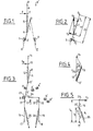
- the conventional double change-over contact with neutral point overrun device consists of a movable contact carrier in the form of a lever 1 (or a blade) articulated, at the one of its ends, around an axis 0 and carrying, at its other end, a double contact pad 2.
- This lever 1 can oscillate between two angular positions OX, OZ for which the double contact pad 2 comes into abutment stroke on two respective fixed contact elements 3, 4.
- the actuation of this lever 1 is effected by means of a spring 5, one end 6 of which is connected to lever 1, and the other end of which 7 is fixed on a support at a point 8 thanks to a mechanical connection 9 possibly flexible.
- the displacement of the end 7 of the spring can therefore be ensured, either by a displacement, for example in translation of the support point 8, or by exerting on this end 7 a force F.
- the relative arrangement of the spring 5 and the lever 1 is provided so that during the trajectory of its end 7, in one direction or the other, the spring 5 becomes collinear with the lever and that in each of said directions , a passage through neutral is obtained, beyond which the lever which was in one of the OX or OZ positions, will tilt until it occupies the other position, bringing the double pad 2 into contact with the element of corresponding fixed contact.
- the end 11 ′ of the lever 11 does not support a contact element but cooperates with the actuating members of two switch devices arranged on either side of this end.
- the crossing of the neutral position by the end 13 of the spring 12 will cause, following the tilting of the lever 11, percussion of one or the other of the actuating members of the switching devices.
- the switch devices each comprise a movable contact carrier 15, 16 consisting of a blade articulated at one of its ends 17, 18 and the other end of which is provided with an element mobile contact 19, 20 which cooperates with a fixed contact element 21, 22.
- This end further comprises an abutment surface 23, 24 which extends in the passage of the end 11 ′ of the lever 11 and thus serves as an actuating member on which the device passing through neutral is struck to effect the separation of the movable contact element 19, 20 and of the fixed contact element 21, 22.
- each of the movable contact carriers 15, 16 is biased by a respective return spring 25, 26 tending to apply the movable contact element 19, 20 against the fixed contact element 21, 22 which corresponds to it.
- this spring 25, 26 whose action is antagonistic to that of the spring 12 when the end 11 ′ of the lever 11 cooperates with the abutment surface 23, 24 of the movable contact element 15 , 16 which is associated with it, serves to ensure a slight anticipation of the passage from neutral.
- stops can act as well on the lever 11, as is the case of the stops A, A ', A ", as on the movable contact carriers 15, 16. This is the reason why there are shown stops B, B ', B "corresponding to this second case.
- Manual reset can, for its part, be effected by a displacement of the stop A "(or B") until it occupies the position of the stop A '(or B').
- the advantage of the device described above consists in that it eliminates the risk of having a zero contact pressure of the mobile and fixed contact elements both on tripping and on resetting. This makes it possible to have better reliability of the control of subordinate members and thereby avoid known disturbances (micro-cuts, beats) encountered with certain conventional devices with exceeding dead center.
- this device is particularly suitable for serving as a trigger / signaling element for a thermal relay.
- the force Fc supplied in the rest position perpendicular to the end 11 ′ of the lever 11 has the expression: this force canceling out when the angle a is zero, that is to say when the spring 12 is in the axis of the lever 11.
- the force F c supplied to the end 11 ′ of the lever 11 depends only on the force F R assumed to be constant and the angle a assumed to be small. It can therefore be assumed that the force / stroke diagram at the end 11 ′ of the lever 11 is linear during the tilting.
- the force Fo supplied at the contact surface 24 by the movable contact carrier 16 and its spring 26 has the expression: in which the expressions 1 5 , 1 6 , F 2 and 8 are the counterparts of the expressions 1 3 , 1 4 , Fi and y.
- the force / stroke diagrams of these movable contact carriers are symmetrical .
- the force F F supplied at rest by the movable contact carrier 15 is antagonistic to that Fc of the lever 11.
- the action of the bimetallic strips on the end 13 will, by deforming the spring 12, reduce the angle a and the force Fc .
- Fc becomes slightly lower than F F
- the lever 11 can swing certainly until its second stable state. It is therefore necessary that in passing, it can provide on the abutment surface 24 a force greater than that of the resistant force provided by the spring 26 of the movable contact carrier 16 to cause the opening of the contact elements 20, 22 .
- this passage must be able to take place technically outside kinetic energy, that is to say that statically, the motor force produced by the lever 11 and the movable contact carrier 15 is greater than the resistant force exerted by the abutment surface 24.
- the slope of the motor force Fc must be much greater than that of the resistant forces exerted by the movable contact carriers.
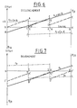
- FIGS. 6 and 7 This particularity is illustrated by the diagrams of FIGS. 6 (triggering) and 7 (rearming) on each of which is plotted on the abscissa a racing scale and on the ordinate, a force scale. These two scales are in arbitrary units. These diagrams are representative of the forces and strokes at the abutment surfaces 23 and 24. For reasons of symmetry, the total stroke has been divided into three substantially equal parts.
- the abscissa point 1 corresponds to the attack on the abutment surface 24 of the movable contact carrier 16 by the end 11 ′ of the lever 11.
- the abscissa point 2 corresponds to the closing of the switch device comprising the contacts 19 and 21.
- the abscissa point 3 corresponds to the triggered state.
- the sawtooth curve OABCDE represents the result (algebraic sum) of the forces involved at the abutment surfaces 23, 24.
- the automatic reset of the device is carried out by means of a reverse process which is illustrated in FIG. 7.
- the invention proposes a solution making it possible to produce a mobile contact carrier having an almost zero slope c.
- this movable contact carrier consists of a contact blade 30 pivotally mounted at one of its ends by means of a Y joint and movable between two angular positions YS, YS '.
- This blade 30 is biased by a spring 31 whose fixed point of attachment 32 is located on a straight line D passing through the articulation Y and perpendicular to the blade 30, when the latter occupies a median position between the two positions YS, YS '.
Landscapes
- Electrophonic Musical Instruments (AREA)
- Mechanisms For Operating Contacts (AREA)
- Mechanical Control Devices (AREA)
- Thermally Actuated Switches (AREA)
- Fluid-Pressure Circuits (AREA)
- Hybrid Cells (AREA)
- Primary Cells (AREA)
- Mechanical Operated Clutches (AREA)
- Secondary Cells (AREA)
- Curing Cements, Concrete, And Artificial Stone (AREA)
- Working-Up Tar And Pitch (AREA)
- Interface Circuits In Exchanges (AREA)
- Transmitters (AREA)
- Gears, Cams (AREA)
- Electronic Switches (AREA)
- Fittings On The Vehicle Exterior For Carrying Loads, And Devices For Holding Or Mounting Articles (AREA)
- Brushes (AREA)
- Massaging Devices (AREA)
- Toys (AREA)
- Push-Button Switches (AREA)
- Driving Mechanisms And Operating Circuits Of Arc-Extinguishing High-Tension Switches (AREA)
Priority Applications (1)
| Application Number | Priority Date | Filing Date | Title |
|---|---|---|---|
| AT87401599T ATE72357T1 (de) | 1986-08-14 | 1987-07-08 | Schaltvorrichtung mit symmetrischer perkussion unter verwendung eines sprungwerkes mit ueberschreitung eines totpunktes. |
Applications Claiming Priority (2)
| Application Number | Priority Date | Filing Date | Title |
|---|---|---|---|
| FR8611737A FR2602908B1 (fr) | 1986-08-14 | 1986-08-14 | Dispositif de commutation a double percussion, utilisant un dispositif a depassement de point mort |
| FR8611737 | 1986-08-14 |
Publications (2)
| Publication Number | Publication Date |
|---|---|
| EP0256901A1 true EP0256901A1 (de) | 1988-02-24 |
| EP0256901B1 EP0256901B1 (de) | 1992-01-29 |
Family
ID=9338302
Family Applications (1)
| Application Number | Title | Priority Date | Filing Date |
|---|---|---|---|
| EP87401599A Expired - Lifetime EP0256901B1 (de) | 1986-08-14 | 1987-07-08 | Schaltvorrichtung mit symmetrischer Perkussion unter Verwendung eines Sprungwerkes mit Überschreitung eines Totpunktes |
Country Status (20)
| Country | Link |
|---|---|
| US (1) | US4841106A (de) |
| EP (1) | EP0256901B1 (de) |
| JP (1) | JPH07101574B2 (de) |
| KR (1) | KR900005868B1 (de) |
| AT (1) | ATE72357T1 (de) |
| AU (1) | AU595348B2 (de) |
| BE (1) | BE1004511A4 (de) |
| BR (1) | BR8703920A (de) |
| CA (1) | CA1274563A (de) |
| CH (1) | CH673173A5 (de) |
| DE (1) | DE3776459D1 (de) |
| DK (1) | DK169244B1 (de) |
| ES (1) | ES2008175A6 (de) |
| FI (1) | FI88085C (de) |
| FR (1) | FR2602908B1 (de) |
| GB (1) | GB2193842B (de) |
| IN (1) | IN172195B (de) |
| IT (1) | IT1222112B (de) |
| MY (1) | MY101310A (de) |
| ZA (1) | ZA875460B (de) |
Cited By (1)
| Publication number | Priority date | Publication date | Assignee | Title |
|---|---|---|---|---|
| FR2618019A1 (fr) * | 1987-07-08 | 1989-01-13 | Telemecanique Electrique | Relais thermique |
Families Citing this family (3)
| Publication number | Priority date | Publication date | Assignee | Title |
|---|---|---|---|---|
| FR2602908B1 (fr) * | 1986-08-14 | 1993-09-24 | Telemecanique Electrique | Dispositif de commutation a double percussion, utilisant un dispositif a depassement de point mort |
| US6492606B1 (en) | 2001-08-21 | 2002-12-10 | Electroswitch Corporation | Snap action switch |
| CA3053044A1 (en) | 2019-08-26 | 2021-02-26 | Alpha Technologies Ltd. | Bi-stable transfer switch |
Citations (4)
| Publication number | Priority date | Publication date | Assignee | Title |
|---|---|---|---|---|
| DE1907420A1 (de) * | 1969-02-14 | 1971-01-21 | Danfoss As | Bimetallschalter mit Schnappsystem |
| DE2043740A1 (de) * | 1970-08-28 | 1972-03-02 | Siemens Ag | Meß oder Regelgerat |
| EP0053194A1 (de) * | 1980-11-28 | 1982-06-09 | Square D Starkstrom GmbH | Kontaktvorrichtung |
| FR2536906A1 (fr) * | 1982-11-25 | 1984-06-01 | Telemecanique Electrique | Relais thermique a reenclenchement automatique ajustable |
Family Cites Families (8)
| Publication number | Priority date | Publication date | Assignee | Title |
|---|---|---|---|---|
| US1768943A (en) * | 1929-08-10 | 1930-07-01 | Minneapolishoneywell Regulator | Switch |
| US2752446A (en) * | 1953-10-19 | 1956-06-26 | John E Carlson | Snap switch |
| AU3537271A (en) * | 1970-12-17 | 1973-05-10 | Westinghouse Electric Corporation | Improvements in or relating to circuit interrupter |
| JPS499586U (de) * | 1972-04-24 | 1974-01-26 | ||
| JPS5037394A (de) * | 1973-08-06 | 1975-04-08 | ||
| JPS539886U (de) * | 1976-07-09 | 1978-01-27 | ||
| SU698064A1 (ru) * | 1978-06-19 | 1979-11-15 | Специальное Конструкторское Бюро По Приборостроению | Микровыключатель |
| FR2602908B1 (fr) * | 1986-08-14 | 1993-09-24 | Telemecanique Electrique | Dispositif de commutation a double percussion, utilisant un dispositif a depassement de point mort |
-
1986
- 1986-08-14 FR FR8611737A patent/FR2602908B1/fr not_active Expired - Fee Related
-
1987
- 1987-07-08 DE DE8787401599T patent/DE3776459D1/de not_active Expired - Lifetime
- 1987-07-08 EP EP87401599A patent/EP0256901B1/de not_active Expired - Lifetime
- 1987-07-08 AT AT87401599T patent/ATE72357T1/de not_active IP Right Cessation
- 1987-07-13 IN IN587/DEL/87A patent/IN172195B/en unknown
- 1987-07-13 BE BE8700771A patent/BE1004511A4/fr not_active IP Right Cessation
- 1987-07-16 MY MYPI87001030A patent/MY101310A/en unknown
- 1987-07-16 GB GB8716807A patent/GB2193842B/en not_active Expired - Lifetime
- 1987-07-16 CH CH2712/87A patent/CH673173A5/fr not_active IP Right Cessation
- 1987-07-21 AU AU75963/87A patent/AU595348B2/en not_active Ceased
- 1987-07-23 IT IT21419/87A patent/IT1222112B/it active
- 1987-07-24 ZA ZA875460A patent/ZA875460B/xx unknown
- 1987-07-30 BR BR8703920A patent/BR8703920A/pt not_active IP Right Cessation
- 1987-08-04 CA CA000543702A patent/CA1274563A/fr not_active Expired - Lifetime
- 1987-08-13 FI FI873515A patent/FI88085C/fi not_active IP Right Cessation
- 1987-08-13 US US07/084,730 patent/US4841106A/en not_active Expired - Lifetime
- 1987-08-13 KR KR1019870008902A patent/KR900005868B1/ko not_active Expired
- 1987-08-14 JP JP62202988A patent/JPH07101574B2/ja not_active Expired - Fee Related
- 1987-08-14 DK DK426287A patent/DK169244B1/da not_active IP Right Cessation
- 1987-08-14 ES ES8702414A patent/ES2008175A6/es not_active Expired
Patent Citations (4)
| Publication number | Priority date | Publication date | Assignee | Title |
|---|---|---|---|---|
| DE1907420A1 (de) * | 1969-02-14 | 1971-01-21 | Danfoss As | Bimetallschalter mit Schnappsystem |
| DE2043740A1 (de) * | 1970-08-28 | 1972-03-02 | Siemens Ag | Meß oder Regelgerat |
| EP0053194A1 (de) * | 1980-11-28 | 1982-06-09 | Square D Starkstrom GmbH | Kontaktvorrichtung |
| FR2536906A1 (fr) * | 1982-11-25 | 1984-06-01 | Telemecanique Electrique | Relais thermique a reenclenchement automatique ajustable |
Cited By (1)
| Publication number | Priority date | Publication date | Assignee | Title |
|---|---|---|---|---|
| FR2618019A1 (fr) * | 1987-07-08 | 1989-01-13 | Telemecanique Electrique | Relais thermique |
Also Published As
| Publication number | Publication date |
|---|---|
| FR2602908B1 (fr) | 1993-09-24 |
| DK426287A (da) | 1988-02-15 |
| FI88085C (fi) | 1993-03-25 |
| KR900005868B1 (ko) | 1990-08-13 |
| ZA875460B (en) | 1988-02-04 |
| MY101310A (en) | 1991-09-05 |
| JPS6348713A (ja) | 1988-03-01 |
| FR2602908A1 (fr) | 1988-02-19 |
| KR880003358A (ko) | 1988-05-16 |
| IT1222112B (it) | 1990-08-31 |
| FI873515L (fi) | 1988-02-15 |
| GB2193842B (en) | 1990-02-14 |
| ES2008175A6 (es) | 1989-07-16 |
| GB2193842A (en) | 1988-02-17 |
| FI873515A0 (fi) | 1987-08-13 |
| DK169244B1 (da) | 1994-09-19 |
| AU7596387A (en) | 1988-02-18 |
| ATE72357T1 (de) | 1992-02-15 |
| DK426287D0 (da) | 1987-08-14 |
| GB8716807D0 (en) | 1987-08-19 |
| CA1274563A (fr) | 1990-09-25 |
| EP0256901B1 (de) | 1992-01-29 |
| AU595348B2 (en) | 1990-03-29 |
| BE1004511A4 (fr) | 1992-12-08 |
| BR8703920A (pt) | 1988-04-05 |
| IN172195B (de) | 1993-05-01 |
| US4841106A (en) | 1989-06-20 |
| FI88085B (fi) | 1992-12-15 |
| CH673173A5 (de) | 1990-02-15 |
| JPH07101574B2 (ja) | 1995-11-01 |
| DE3776459D1 (de) | 1992-03-12 |
| IT8721419A0 (it) | 1987-07-23 |
Similar Documents
| Publication | Publication Date | Title |
|---|---|---|
| EP0179677B1 (de) | Schaltvorrichtung mit variabler Zusammensetzung | |
| EP0789380B1 (de) | Betätigungsmechanismus für einen Lastschalter mit durch einen kurzschlussentkuppelbare Verriegelung | |
| EP0977233A1 (de) | Leistungsschalter mit hoher elektrodynamischer Festigkeit und Ausschaltleistung | |
| FR2578354A1 (fr) | Disjoncteur pouvant fonctionner en interrupteur | |
| FR2816106A1 (fr) | Disjoncteur | |
| EP0338930A1 (de) | Lastschalter oder Differential-Lastschalter | |
| EP0079818A1 (de) | Schaltgerät mit Anordnungen zur Selbstunterbrechung von Leistungsstromkreisen und mit einer örtlichen Antriebsvorrichtung | |
| EP0161946A1 (de) | An einen Schutzschalter ankuppelbare Zusatzeinheit | |
| EP0256901B1 (de) | Schaltvorrichtung mit symmetrischer Perkussion unter Verwendung eines Sprungwerkes mit Überschreitung eines Totpunktes | |
| EP0369844B1 (de) | Schlossmechanismus für ein strombegrenzendes Schütz | |
| EP0325501B1 (de) | Automatische Schalter, insbesondere Differential- und Schutzschaltern | |
| EP0657909B1 (de) | Elektrischer Schalter mit Fehlerauslösung | |
| EP0798756B1 (de) | Betätigungsmechanismus für elektrischen Schutzschalter mit grossen Öffnungswinkel | |
| EP1383150B1 (de) | Schalter mit Auslöseeinrichtung | |
| EP0130208B1 (de) | Schalter mit bedientem öffnen und schliessen und mit automatischer öffnung im fall eines überstromes | |
| EP0032870B1 (de) | Auf ein Gestell montierbares Gerät zum Steuern der Bewegung eines Armes und Anwendung dieses Gerätes als Schalter | |
| EP0218497B1 (de) | Schutzschalter mit federnder Lasche | |
| EP0114541B1 (de) | Auslöseeinrichtung für Schaltgeräte mit automatischer oder bedienter Öffnung | |
| EP0370885B1 (de) | Mechanische Knickstütze | |
| EP0926693B1 (de) | Selektiver Auslöser für Leistungsschalter | |
| EP0693765A1 (de) | Elektromagnetischer Auslöser für einen Niederspannungsschutzschalter | |
| EP0271366B1 (de) | Ferngesteuerter Schalter mit einem Hilfsumschalter in dessen Ansteuerschaltung | |
| EP3232459B1 (de) | Elektrisches gerät zum leitungsschutz | |
| FR2621417A1 (fr) | Interrupteur de protection a ecran de coupure d'arc | |
| EP0037295B1 (de) | Schnellschalter mit einer Vorrichtung zur Stossicherung |
Legal Events
| Date | Code | Title | Description |
|---|---|---|---|
| PUAI | Public reference made under article 153(3) epc to a published international application that has entered the european phase |
Free format text: ORIGINAL CODE: 0009012 |
|
| 17P | Request for examination filed |
Effective date: 19870710 |
|
| AK | Designated contracting states |
Kind code of ref document: A1 Designated state(s): AT DE NL SE |
|
| 17Q | First examination report despatched |
Effective date: 19900530 |
|
| RAP1 | Party data changed (applicant data changed or rights of an application transferred) |
Owner name: TELEMECANIQUE |
|
| GRAA | (expected) grant |
Free format text: ORIGINAL CODE: 0009210 |
|
| AK | Designated contracting states |
Kind code of ref document: B1 Designated state(s): AT DE NL SE |
|
| REF | Corresponds to: |
Ref document number: 72357 Country of ref document: AT Date of ref document: 19920215 Kind code of ref document: T |
|
| REF | Corresponds to: |
Ref document number: 3776459 Country of ref document: DE Date of ref document: 19920312 |
|
| PLBE | No opposition filed within time limit |
Free format text: ORIGINAL CODE: 0009261 |
|
| STAA | Information on the status of an ep patent application or granted ep patent |
Free format text: STATUS: NO OPPOSITION FILED WITHIN TIME LIMIT |
|
| 26N | No opposition filed | ||
| EAL | Se: european patent in force in sweden |
Ref document number: 87401599.3 |
|
| PGFP | Annual fee paid to national office [announced via postgrant information from national office to epo] |
Ref country code: AT Payment date: 20050617 Year of fee payment: 19 |
|
| PGFP | Annual fee paid to national office [announced via postgrant information from national office to epo] |
Ref country code: SE Payment date: 20050620 Year of fee payment: 19 |
|
| PGFP | Annual fee paid to national office [announced via postgrant information from national office to epo] |
Ref country code: NL Payment date: 20050623 Year of fee payment: 19 |
|
| PGFP | Annual fee paid to national office [announced via postgrant information from national office to epo] |
Ref country code: DE Payment date: 20050704 Year of fee payment: 19 |
|
| PG25 | Lapsed in a contracting state [announced via postgrant information from national office to epo] |
Ref country code: AT Free format text: LAPSE BECAUSE OF NON-PAYMENT OF DUE FEES Effective date: 20060708 |
|
| PG25 | Lapsed in a contracting state [announced via postgrant information from national office to epo] |
Ref country code: SE Free format text: LAPSE BECAUSE OF NON-PAYMENT OF DUE FEES Effective date: 20060709 |
|
| PG25 | Lapsed in a contracting state [announced via postgrant information from national office to epo] |
Ref country code: NL Free format text: LAPSE BECAUSE OF NON-PAYMENT OF DUE FEES Effective date: 20070201 Ref country code: DE Free format text: LAPSE BECAUSE OF NON-PAYMENT OF DUE FEES Effective date: 20070201 |
|
| EUG | Se: european patent has lapsed | ||
| NLV4 | Nl: lapsed or anulled due to non-payment of the annual fee |
Effective date: 20070201 |