EP0254909B1 - Busette de coulée réfractaire - Google Patents
Busette de coulée réfractaire Download PDFInfo
- Publication number
- EP0254909B1 EP0254909B1 EP87109646A EP87109646A EP0254909B1 EP 0254909 B1 EP0254909 B1 EP 0254909B1 EP 87109646 A EP87109646 A EP 87109646A EP 87109646 A EP87109646 A EP 87109646A EP 0254909 B1 EP0254909 B1 EP 0254909B1
- Authority
- EP
- European Patent Office
- Prior art keywords
- pouring spout
- pouring
- guide element
- spout according
- outflow
- Prior art date
- Legal status (The legal status is an assumption and is not a legal conclusion. Google has not performed a legal analysis and makes no representation as to the accuracy of the status listed.)
- Expired
Links
- 239000002184 metal Substances 0.000 claims description 27
- 229910052751 metal Inorganic materials 0.000 claims description 27
- 238000005266 casting Methods 0.000 claims description 5
- 229910000831 Steel Inorganic materials 0.000 claims description 4
- 238000009749 continuous casting Methods 0.000 claims description 4
- 239000010959 steel Substances 0.000 claims description 4
- 230000001154 acute effect Effects 0.000 claims description 3
- 239000007788 liquid Substances 0.000 claims description 2
- 150000002739 metals Chemical class 0.000 claims description 2
- 230000007423 decrease Effects 0.000 claims 1
- 238000009826 distribution Methods 0.000 description 5
- 238000007711 solidification Methods 0.000 description 2
- 230000008023 solidification Effects 0.000 description 2
- 238000009827 uniform distribution Methods 0.000 description 2
- 230000015572 biosynthetic process Effects 0.000 description 1
- 238000001816 cooling Methods 0.000 description 1
- 238000013016 damping Methods 0.000 description 1
- 230000002349 favourable effect Effects 0.000 description 1
- 229910001338 liquidmetal Inorganic materials 0.000 description 1
- 238000000034 method Methods 0.000 description 1
- 239000000843 powder Substances 0.000 description 1
- 230000000630 rising effect Effects 0.000 description 1
Images
Classifications
-
- B—PERFORMING OPERATIONS; TRANSPORTING
- B22—CASTING; POWDER METALLURGY
- B22D—CASTING OF METALS; CASTING OF OTHER SUBSTANCES BY THE SAME PROCESSES OR DEVICES
- B22D11/00—Continuous casting of metals, i.e. casting in indefinite lengths
- B22D11/10—Supplying or treating molten metal
-
- B—PERFORMING OPERATIONS; TRANSPORTING
- B22—CASTING; POWDER METALLURGY
- B22D—CASTING OF METALS; CASTING OF OTHER SUBSTANCES BY THE SAME PROCESSES OR DEVICES
- B22D41/00—Casting melt-holding vessels, e.g. ladles, tundishes, cups or the like
- B22D41/50—Pouring-nozzles
Definitions
- the invention relates to a fireproof pouring tube for the continuous casting of molten metals, in particular liquid steel into thin slabs in a mold which is preferably funnel-shaped in the middle in the upper region and has outflow openings opposite one another in front of a closed bottom in the tube wall and facing the narrow sides of the mold.
- Such a known pouring tube (Stahleisen-Schriften, Issue 8, "The Continuous Casting of Steel", page 21) is more advantageous compared to a pouring tube that is open at the bottom because, as a result of the division and deflection of the pouring jet, turbulence harmful to the solidification develops the mold can be avoided. It is disadvantageous, however, that when the mold is filled, metal splashes up and cakes to the upper regions of the mold wall, as a result of which the formation of strand shells is prevented and breakthroughs can be caused. In addition, the distribution of the molten metal is not optimal. Too little molten metal gets into the upper areas, so that there is a temperature gradient towards these areas. This creates an uneven solidification front across the cross section of the strand to be cast.
- molten metal can also be brought into areas of the mold that are further away from the pouring tube, but then there is an area in the immediate vicinity of the pouring tube in which molten metal is not directly from the pouring tube can reach.
- the invention has for its object to provide a pouring tube of the type mentioned, in which there is no splashing and caking of metal splashes on the cooled mold wall at the start of pouring and in normal casting operation the molten metal over the cross section of the mold better than in known pouring tubes is distributed.
- outflow openings each have a roof-shaped guide element starting from the tube wall and a tear-off edge formed by the bottom and / or the tube wall in the lower region.
- the guide element Because of the guide element, it is prevented that molten metal splashes up to the upper areas of the cooled mold wall and fills there when it is filled. When the mold is filled, the guide element ensures that molten metal also reaches the upper areas on the narrow sides of the mold wall and that no zone of lower temperature is formed here. Because of the tear-off edge in the lower area, molten metal also gets directly into the area below the pouring tube, so that the result is that the molten metal is evenly distributed over the entire cross section of the mold.
- each roof-shaped guide element on both sides of each outflow opening extends to the lower tear-off edge.
- an embodiment is particularly advantageous in which the distance of the free edge of the lateral parts of the guide element from the tube wall from the upper region of the guide element to the tear-off edge provided in the lower region of the outflow opening becomes, in particular, continuously smaller.
- each tear-off edge lies in a plane running perpendicular to the pipe axis.
- the outflow openings should be arched in the upper area.
- the guide element itself is preferably adapted to the shape of the associated outflow opening.
- the uniform distribution of the molten metal can be further improved in that the clear width of each outflow opening increases from the upper region to the tear-off edge.
- the tear-off edge should extend over the entire inside width of the pipe.
- the part of the guide element lying above the outflow opening forms an acute angle with the part of the tube wall lying above it.
- An angle that is greater than 70 ° has proven to be expedient.
- the clear width of the outflow openings is at most equal to the distance between the broad side walls of the mold in its lower region, which determines the strand format.
- the pouring tube in order to be able to introduce enough molten metal into the mold in the case of molds for wide thin slabs, the pouring tube, as is known per se, can have an oval cross section.
- the outflow openings are provided on the wall areas with the smaller radius of curvature.
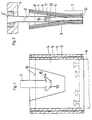
- a pouring tube 2 with a conical head piece 2 ' is held in the bottom of a distribution vessel 1 for liquid metal.
- the pouring tube 2 projects with its lower end into a mold 3 for casting thin slabs of the order of magnitude of preference wise 20-100 mm.
- the mold 3 is formed by two opposite broad side walls 4 and two opposite narrow side walls 5.
- the wide side walls 4 and the narrow side walls 5 are provided with cooling channels 6.
- the broad side walls 4 form in the middle above a format-determining parallel section 7 an upwardly funnel-shaped pouring area 8 for receiving the lower end of the pouring tube 2.
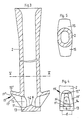
- the pouring tube 2 has an oval flow cross section and is closed at its lower end by a base plate 13. Immediately above the base plate 13 on the narrow sides of the tube wall, arched outlet openings 1 are provided on opposite sides.
- the lower edge 11 'of the outflow opening 11, formed by the base plate 13, lies in a plane perpendicular to the axis of the pouring tube 2 and acts as a tear-off edge.
- the maximum width b of the outflow opening 11 at the tear-off edge 11 ' is equal to or smaller than the clear distance d between the wide side walls 4 of the mold 3 in the format-determining parallel section 7.
- the inside of the base plate 13 is arched into a vertex 14 in an arc shape towards the inside of the pouring tube 2. From the apex 14 of this bulge, guide surfaces 14 'fall in an arc towards the tear-off edges 11'.
- a roof-shaped guide element 15 connects to the lateral edges and the upper edge of the outlet opening 11 shaped like an archway.
- the free edges 15 "of the side parts 15 'of this roof-shaped guide element 15 are chamfered from the upper, most distant part 15" to the tear-off edge 11' in the lower region of the outflow opening 11.
- the molten metal flowing into the pouring tube 2 is divided by the apex 14 and the guide surface 14 'of the bulge of the base plate 13 and exits through the outflow openings 11. Since the mold is not yet filled with the flow-damping molten metal in this phase, the guide element 15 prevents metal from splashing upwards and to the sides and caking on the cooled broad side walls 4 and narrow side walls 5.
- the molten metal flowing out into the mold 3 solidifies on the wall of the mold 3 and connects to a start-up head 9 which closes the mold 3 from below. As soon as the rising mold level 10 exceeds the lateral openings 11, it is covered with mold powder.
- each guide element 15 prevent molten metal from flowing directly against the nearby broad side walls 4 and, together with the upper, far preferred part 15 ", guide the flow of the molten metal into the upper regions near the narrow side walls 5.
Landscapes
- Engineering & Computer Science (AREA)
- Mechanical Engineering (AREA)
- Casting Support Devices, Ladles, And Melt Control Thereby (AREA)
- Continuous Casting (AREA)
- Molds, Cores, And Manufacturing Methods Thereof (AREA)
Claims (13)
Priority Applications (2)
| Application Number | Priority Date | Filing Date | Title |
|---|---|---|---|
| AT87109646T ATE41339T1 (de) | 1986-07-12 | 1987-07-04 | Feuerfestes giessrohr. |
| IN523/CAL/87A IN165890B (fr) | 1986-07-12 | 1987-07-08 |
Applications Claiming Priority (2)
| Application Number | Priority Date | Filing Date | Title |
|---|---|---|---|
| DE19863623660 DE3623660A1 (de) | 1986-07-12 | 1986-07-12 | Feuerfestes giessrohr |
| DE3623660 | 1986-07-12 |
Publications (2)
| Publication Number | Publication Date |
|---|---|
| EP0254909A1 EP0254909A1 (fr) | 1988-02-03 |
| EP0254909B1 true EP0254909B1 (fr) | 1989-03-15 |
Family
ID=6305111
Family Applications (1)
| Application Number | Title | Priority Date | Filing Date |
|---|---|---|---|
| EP87109646A Expired EP0254909B1 (fr) | 1986-07-12 | 1987-07-04 | Busette de coulée réfractaire |
Country Status (10)
| Country | Link |
|---|---|
| US (1) | US4819840A (fr) |
| EP (1) | EP0254909B1 (fr) |
| JP (1) | JPS6372454A (fr) |
| KR (1) | KR880001352A (fr) |
| CN (1) | CN87104752A (fr) |
| BR (1) | BR8703549A (fr) |
| DE (2) | DE3623660A1 (fr) |
| ES (1) | ES2007301B3 (fr) |
| GR (1) | GR3000021T3 (fr) |
| ZA (1) | ZA875017B (fr) |
Families Citing this family (23)
| Publication number | Priority date | Publication date | Assignee | Title |
|---|---|---|---|---|
| JPS63303679A (ja) * | 1987-06-05 | 1988-12-12 | Toshiba Ceramics Co Ltd | 鋳造用浸漬ノズル |
| DE3811751A1 (de) * | 1988-04-08 | 1989-10-19 | Schloemann Siemag Ag | Tauchgiessrohr zum einleiten von metallschmelze in eine metallbandgiesskokille |
| DE3918228C2 (de) * | 1989-06-03 | 1996-11-07 | Schloemann Siemag Ag | Tauchgießrohr zum Einleiten von Stahlschmelze in eine Stranggießkokille |
| US5205343A (en) * | 1989-06-03 | 1993-04-27 | Sms Schloemann-Siemag Aktiengesellschaft | Pouring tube for feeding molten steel into a continuous casting mold |
| DE4032624A1 (de) * | 1990-10-15 | 1992-04-16 | Schloemann Siemag Ag | Tauchgiessrohr zum einleiten von stahlschmelze in eine stranggiesskokille |
| US5944261A (en) * | 1994-04-25 | 1999-08-31 | Vesuvius Crucible Company | Casting nozzle with multi-stage flow division |
| US5785880A (en) * | 1994-03-31 | 1998-07-28 | Vesuvius Usa | Submerged entry nozzle |
| IT1267242B1 (it) * | 1994-05-30 | 1997-01-28 | Danieli Off Mecc | Scaricatore per bramme sottili |
| US5879721A (en) * | 1996-08-28 | 1999-03-09 | Ebaa Iron, Inc. | Movable pouring basin |
| UA51734C2 (uk) * | 1996-10-03 | 2002-12-16 | Візувіус Крусібл Компані | Занурений стакан для пропускання рідкого металу і спосіб пропускання рідкого металу через нього |
| DE19802809A1 (de) * | 1998-01-27 | 1999-07-29 | Km Europa Metal Ag | Flüssigkeitsgekühlte Kokille |
| KR100488988B1 (ko) * | 2000-06-21 | 2005-05-11 | 주식회사 포스코 | 침지노즐 |
| CZ20031269A3 (cs) * | 2000-10-27 | 2004-01-14 | The Ohio State University | Způsob a zařízení k řízení stojatých povrchových vln a turbulence v nádobě na plynulé lití |
| US6543656B1 (en) | 2000-10-27 | 2003-04-08 | The Ohio State University | Method and apparatus for controlling standing surface wave and turbulence in continuous casting vessel |
| US7090918B2 (en) * | 2001-01-11 | 2006-08-15 | Vesuvius Crucible Company | Externally glazed article |
| US6932250B2 (en) * | 2003-02-14 | 2005-08-23 | Isg Technologies Inc. | Submerged entry nozzle and method for maintaining a quiet casting mold |
| DE50301315D1 (de) * | 2003-08-01 | 2006-02-16 | Hof Te Fiennes N V | Giesssystem und Verfahren zum Vergiessen von NE-Metallschmelzen |
| WO2005070589A1 (fr) * | 2004-01-23 | 2005-08-04 | Sumitomo Metal Industries, Ltd | Busette immergee pour la coulee continue et procede de coulee continue utilisant cette busette immergee |
| US8225845B2 (en) | 2009-12-04 | 2012-07-24 | Nucor Corporation | Casting delivery nozzle |
| EP2444177A1 (fr) * | 2010-10-20 | 2012-04-25 | Vesuvius Group S.A | Tube pour l'écoulement de métal liquide |
| JP5578112B2 (ja) * | 2011-03-02 | 2014-08-27 | 新日鐵住金株式会社 | 誘導加熱装置の冷却方法 |
| CN104325126A (zh) * | 2014-10-13 | 2015-02-04 | 上海大学 | 板坯连铸过程控制金属流体流动的浸入式水口 |
| CN111974981B (zh) | 2019-05-23 | 2023-08-29 | 维苏威集团有限公司 | 浇铸水口 |
Family Cites Families (12)
| Publication number | Priority date | Publication date | Assignee | Title |
|---|---|---|---|---|
| BE692176A (fr) * | 1966-03-15 | 1967-06-16 | ||
| CH445034A (de) * | 1966-10-18 | 1967-10-15 | Metacon Ag | Ausgussvorrichtung |
| DE1817067B1 (de) * | 1968-12-21 | 1971-04-29 | Mannesmann Ag | Einrichtung zum abscheiden von verunreinigungen aus fluessi gem stahl waehrend des stranggiessens und ein verfahren dazu |
| DE1939170B2 (de) * | 1969-07-29 | 1971-04-22 | Mannesmann Ag | Einrichtung zum verteilen einer schmelze in einer anlage zum stranggiessen von stahl |
| DE1959097C2 (de) * | 1969-11-20 | 1973-10-04 | Mannesmann Ag, 4000 Duesseldorf | Vorrichtung beim Stranggießen zum Ver teilen eiern Stahlschmelze |
| BE790371A (fr) * | 1971-10-21 | 1973-02-15 | Voest Ag | Tube de coulee refractaire pour le coulage en continu de metauxen fusion |
| CH557707A (de) * | 1973-05-07 | 1975-01-15 | Concast Ag | Vorrichtung zum einbringen einer stahlschmelze in den giesskopf einer stranggiesskokille. |
| DE2342820B1 (de) * | 1973-08-24 | 1974-08-15 | Kloeckner Werke Ag | Tauchausguss fuer eine Stranggiesskokille |
| US4487251A (en) * | 1982-03-08 | 1984-12-11 | Vesuvius Crucible Company | Continuous casting apparatus and a method of using the same |
| JPS6123558A (ja) * | 1984-06-28 | 1986-02-01 | Nippon Kokan Kk <Nkk> | 連続鋳造用浸漬ノズル |
| IT1177924B (it) * | 1984-07-24 | 1987-08-26 | Centro Speriment Metallurg | Perfezionamento negli scaricatori di colata continua |
| US4662546A (en) * | 1985-07-30 | 1987-05-05 | Allegheny Ludlum Corporation | Submerged nozzle for use in the continuous casting of slabs |
-
1986
- 1986-07-12 DE DE19863623660 patent/DE3623660A1/de not_active Withdrawn
-
1987
- 1987-07-04 DE DE8787109646T patent/DE3760064D1/de not_active Expired
- 1987-07-04 EP EP87109646A patent/EP0254909B1/fr not_active Expired
- 1987-07-04 ES ES87109646T patent/ES2007301B3/es not_active Expired - Lifetime
- 1987-07-09 ZA ZA875017A patent/ZA875017B/xx unknown
- 1987-07-10 BR BR8703549A patent/BR8703549A/pt unknown
- 1987-07-10 US US07/072,088 patent/US4819840A/en not_active Expired - Fee Related
- 1987-07-10 JP JP62171302A patent/JPS6372454A/ja active Pending
- 1987-07-11 CN CN198787104752A patent/CN87104752A/zh active Pending
- 1987-07-11 KR KR1019870007474A patent/KR880001352A/ko not_active Application Discontinuation
-
1989
- 1989-03-20 GR GR89400019T patent/GR3000021T3/el unknown
Also Published As
| Publication number | Publication date |
|---|---|
| JPS6372454A (ja) | 1988-04-02 |
| ES2007301B3 (es) | 1990-08-16 |
| US4819840A (en) | 1989-04-11 |
| DE3623660A1 (de) | 1988-01-14 |
| ZA875017B (en) | 1988-01-13 |
| CN87104752A (zh) | 1988-03-02 |
| KR880001352A (ko) | 1988-04-22 |
| BR8703549A (pt) | 1988-03-22 |
| DE3760064D1 (en) | 1989-04-20 |
| GR3000021T3 (en) | 1989-10-31 |
| EP0254909A1 (fr) | 1988-02-03 |
Similar Documents
| Publication | Publication Date | Title |
|---|---|---|
| EP0254909B1 (fr) | Busette de coulée réfractaire | |
| DE4142447C3 (de) | Tauchgießrohr - Dünnbramme | |
| DE69702984T2 (de) | Tauchgiessrohr zum stranggiessen von dünnbrammen | |
| DE69514956T2 (de) | Tauchgiessrohr zum Stranggiessen | |
| DE2527585A1 (de) | Giessrohr mit einer bodenoeffnung zum kontinuierlichen stahlstranggiessen | |
| EP0482423B1 (fr) | Tube plongeur de coulée pour l'introduction d'acier liquide dans une lingotière de coulée continue | |
| DE2442915A1 (de) | Giessrohr mit geschlossenem boden und einander gegenueberliegenden seitlichen oeffnungen | |
| DE2417512A1 (de) | Verfahren zum einbringen von stahl in eine stranggiesskokille und vorrichtung dazu | |
| EP0630711B1 (fr) | Busette de coulée immergée | |
| DE2132294A1 (de) | Verfahren und Vorrichtung zum Giessen von Metallschmelze | |
| DE4116723C1 (en) | Immersion tundish outlet giving quiescent melt flow into mould - includes channel with nozzle shape at inlet to receive stopper, with narrowest section at transition to channel | |
| DE2548585B2 (de) | Vorrichtung zum stranggiessen von stahl | |
| DE2807048A1 (de) | Verfahren und vorrichtung zum behandeln von geschmolzenem metall mit zuschlagstoffen | |
| DE19512208C1 (de) | Tauchausguß zum Gießen von Metall | |
| DE2913024A1 (de) | Verfahren zum kuehlen einer oszillierenden stahl-stranggiesskokille | |
| DE3426107C2 (de) | Schiebeverschluß für den horizontalen Ausguß von Nichteisen-Metallschmelze enthaltenden Gefässen | |
| EP0900609B1 (fr) | Tube plongeur pour introduire un métal fondu, à partir d'un récipient de coulée ou un récipient intermédiaire, dans une coquille | |
| DE2250048A1 (de) | Feuerfestes giessrohr zum stranggiessen schmelzfluessiger metalle | |
| EP1002600B1 (fr) | Tube plongeur pour introduire un métal fondu, dans une coquille pour la coulée en continue de plaques fines | |
| EP0151802B1 (fr) | Dispositif pour l'introduction de métal liquide, en particulier d'acier liquide dans une coquille de coulée continue | |
| DE4319194A1 (de) | Mundstück eines Eintauchausgusses | |
| DE2304943A1 (de) | Feuerfestes giessrohr zum giessen schmelzfluessiger metalle | |
| DE19811957C2 (de) | Anordnung eines Tauchausgusses in einer Kokille zum Stranggießen von Brammen | |
| DE69820595T2 (de) | Radialstrom-Verteiler zum gleichmässigen, nicht turbulenten und nicht tropfenden Stranggiessen von Metallen und entsprechendes Verfahren | |
| DE69809104T2 (de) | Strangiesskokille für Metalle |
Legal Events
| Date | Code | Title | Description |
|---|---|---|---|
| PUAI | Public reference made under article 153(3) epc to a published international application that has entered the european phase |
Free format text: ORIGINAL CODE: 0009012 |
|
| AK | Designated contracting states |
Kind code of ref document: A1 Designated state(s): AT BE CH DE ES FR GB GR IT LI LU NL SE |
|
| 17P | Request for examination filed |
Effective date: 19880226 |
|
| 17Q | First examination report despatched |
Effective date: 19880725 |
|
| ITF | It: translation for a ep patent filed | ||
| GRAA | (expected) grant |
Free format text: ORIGINAL CODE: 0009210 |
|
| AK | Designated contracting states |
Kind code of ref document: B1 Designated state(s): AT BE CH DE ES FR GB GR IT LI LU NL SE |
|
| REF | Corresponds to: |
Ref document number: 41339 Country of ref document: AT Date of ref document: 19890415 Kind code of ref document: T |
|
| REF | Corresponds to: |
Ref document number: 3760064 Country of ref document: DE Date of ref document: 19890420 |
|
| ET | Fr: translation filed | ||
| GBT | Gb: translation of ep patent filed (gb section 77(6)(a)/1977) | ||
| REG | Reference to a national code |
Ref country code: GR Ref legal event code: FG4A Free format text: 3000021 |
|
| PG25 | Lapsed in a contracting state [announced via postgrant information from national office to epo] |
Ref country code: LU Free format text: LAPSE BECAUSE OF NON-PAYMENT OF DUE FEES Effective date: 19890731 |
|
| PLBI | Opposition filed |
Free format text: ORIGINAL CODE: 0009260 |
|
| 26 | Opposition filed |
Opponent name: DIDIER-WERKE AG Effective date: 19891212 |
|
| NLR1 | Nl: opposition has been filed with the epo |
Opponent name: DIDIER-WERKE AG |
|
| PGFP | Annual fee paid to national office [announced via postgrant information from national office to epo] |
Ref country code: FR Payment date: 19900622 Year of fee payment: 4 |
|
| PGFP | Annual fee paid to national office [announced via postgrant information from national office to epo] |
Ref country code: CH Payment date: 19900625 Year of fee payment: 4 |
|
| PGFP | Annual fee paid to national office [announced via postgrant information from national office to epo] |
Ref country code: BE Payment date: 19900628 Year of fee payment: 4 |
|
| PGFP | Annual fee paid to national office [announced via postgrant information from national office to epo] |
Ref country code: SE Payment date: 19900629 Year of fee payment: 4 Ref country code: GR Payment date: 19900629 Year of fee payment: 4 Ref country code: AT Payment date: 19900629 Year of fee payment: 4 |
|
| PGFP | Annual fee paid to national office [announced via postgrant information from national office to epo] |
Ref country code: LU Payment date: 19900702 Year of fee payment: 4 |
|
| PGFP | Annual fee paid to national office [announced via postgrant information from national office to epo] |
Ref country code: ES Payment date: 19900703 Year of fee payment: 4 |
|
| PGFP | Annual fee paid to national office [announced via postgrant information from national office to epo] |
Ref country code: NL Payment date: 19900731 Year of fee payment: 4 |
|
| PGFP | Annual fee paid to national office [announced via postgrant information from national office to epo] |
Ref country code: DE Payment date: 19900827 Year of fee payment: 4 |
|
| PLBN | Opposition rejected |
Free format text: ORIGINAL CODE: 0009273 |
|
| STAA | Information on the status of an ep patent application or granted ep patent |
Free format text: STATUS: OPPOSITION REJECTED |
|
| 27O | Opposition rejected |
Effective date: 19910107 |
|
| PG25 | Lapsed in a contracting state [announced via postgrant information from national office to epo] |
Ref country code: GB Effective date: 19910704 Ref country code: AT Effective date: 19910704 |
|
| PG25 | Lapsed in a contracting state [announced via postgrant information from national office to epo] |
Ref country code: SE Effective date: 19910705 Ref country code: ES Free format text: LAPSE BECAUSE OF THE APPLICANT RENOUNCES Effective date: 19910705 |
|
| NLR2 | Nl: decision of opposition | ||
| ITTA | It: last paid annual fee | ||
| PG25 | Lapsed in a contracting state [announced via postgrant information from national office to epo] |
Ref country code: LI Effective date: 19910731 Ref country code: CH Effective date: 19910731 Ref country code: BE Effective date: 19910731 |
|
| BERE | Be: lapsed |
Owner name: THYSSEN STAHL A.G. Effective date: 19910731 |
|
| PG25 | Lapsed in a contracting state [announced via postgrant information from national office to epo] |
Ref country code: GR Free format text: THE PATENT HAS BEEN ANNULLED BY A DECISION OF A NATIONAL AUTHORITY Effective date: 19920131 |
|
| PG25 | Lapsed in a contracting state [announced via postgrant information from national office to epo] |
Ref country code: NL Effective date: 19920201 |
|
| GBPC | Gb: european patent ceased through non-payment of renewal fee | ||
| NLV4 | Nl: lapsed or anulled due to non-payment of the annual fee | ||
| PG25 | Lapsed in a contracting state [announced via postgrant information from national office to epo] |
Ref country code: FR Effective date: 19920331 |
|
| REG | Reference to a national code |
Ref country code: CH Ref legal event code: PL |
|
| PG25 | Lapsed in a contracting state [announced via postgrant information from national office to epo] |
Ref country code: DE Effective date: 19920401 |
|
| REG | Reference to a national code |
Ref country code: FR Ref legal event code: ST |
|
| REG | Reference to a national code |
Ref country code: GR Ref legal event code: MM2A Free format text: 3000021 |
|
| EUG | Se: european patent has lapsed |
Ref document number: 87109646.7 Effective date: 19920210 |
|
| REG | Reference to a national code |
Ref country code: ES Ref legal event code: FD2A Effective date: 19991007 |
|
| PG25 | Lapsed in a contracting state [announced via postgrant information from national office to epo] |
Ref country code: IT Free format text: LAPSE BECAUSE OF NON-PAYMENT OF DUE FEES;WARNING: LAPSES OF ITALIAN PATENTS WITH EFFECTIVE DATE BEFORE 2007 MAY HAVE OCCURRED AT ANY TIME BEFORE 2007. THE CORRECT EFFECTIVE DATE MAY BE DIFFERENT FROM THE ONE RECORDED. Effective date: 20050704 |