EP0254246A2 - Cuvette - Google Patents
Cuvette Download PDFInfo
- Publication number
- EP0254246A2 EP0254246A2 EP87110447A EP87110447A EP0254246A2 EP 0254246 A2 EP0254246 A2 EP 0254246A2 EP 87110447 A EP87110447 A EP 87110447A EP 87110447 A EP87110447 A EP 87110447A EP 0254246 A2 EP0254246 A2 EP 0254246A2
- Authority
- EP
- European Patent Office
- Prior art keywords
- cuvette
- lancet
- generally
- light
- cavity
- Prior art date
- Legal status (The legal status is an assumption and is not a legal conclusion. Google has not performed a legal analysis and makes no representation as to the accuracy of the status listed.)
- Withdrawn
Links
Images


Classifications
-
- G—PHYSICS
- G01—MEASURING; TESTING
- G01N—INVESTIGATING OR ANALYSING MATERIALS BY DETERMINING THEIR CHEMICAL OR PHYSICAL PROPERTIES
- G01N21/00—Investigating or analysing materials by the use of optical means, i.e. using sub-millimetre waves, infrared, visible or ultraviolet light
- G01N21/01—Arrangements or apparatus for facilitating the optical investigation
- G01N21/03—Cuvette constructions
-
- A—HUMAN NECESSITIES
- A61—MEDICAL OR VETERINARY SCIENCE; HYGIENE
- A61B—DIAGNOSIS; SURGERY; IDENTIFICATION
- A61B5/00—Measuring for diagnostic purposes; Identification of persons
- A61B5/145—Measuring characteristics of blood in vivo, e.g. gas concentration, pH value; Measuring characteristics of body fluids or tissues, e.g. interstitial fluid, cerebral tissue
- A61B5/1455—Measuring characteristics of blood in vivo, e.g. gas concentration, pH value; Measuring characteristics of body fluids or tissues, e.g. interstitial fluid, cerebral tissue using optical sensors, e.g. spectral photometrical oximeters
-
- A—HUMAN NECESSITIES
- A61—MEDICAL OR VETERINARY SCIENCE; HYGIENE
- A61B—DIAGNOSIS; SURGERY; IDENTIFICATION
- A61B5/00—Measuring for diagnostic purposes; Identification of persons
- A61B5/15—Devices for taking samples of blood
- A61B5/150007—Details
- A61B5/150015—Source of blood
- A61B5/150022—Source of blood for capillary blood or interstitial fluid
-
- A—HUMAN NECESSITIES
- A61—MEDICAL OR VETERINARY SCIENCE; HYGIENE
- A61B—DIAGNOSIS; SURGERY; IDENTIFICATION
- A61B5/00—Measuring for diagnostic purposes; Identification of persons
- A61B5/15—Devices for taking samples of blood
- A61B5/150007—Details
- A61B5/150374—Details of piercing elements or protective means for preventing accidental injuries by such piercing elements
- A61B5/150534—Design of protective means for piercing elements for preventing accidental needle sticks, e.g. shields, caps, protectors, axially extensible sleeves, pivotable protective sleeves
- A61B5/150541—Breakable protectors, e.g. caps, shields or sleeves, i.e. protectors separated destructively, e.g. by breaking a connecting area
- A61B5/150549—Protectors removed by rotational movement, e.g. torsion or screwing
-
- A—HUMAN NECESSITIES
- A61—MEDICAL OR VETERINARY SCIENCE; HYGIENE
- A61B—DIAGNOSIS; SURGERY; IDENTIFICATION
- A61B5/00—Measuring for diagnostic purposes; Identification of persons
- A61B5/15—Devices for taking samples of blood
- A61B5/150007—Details
- A61B5/150374—Details of piercing elements or protective means for preventing accidental injuries by such piercing elements
- A61B5/150534—Design of protective means for piercing elements for preventing accidental needle sticks, e.g. shields, caps, protectors, axially extensible sleeves, pivotable protective sleeves
- A61B5/150633—Protective sleeves which are axially extensible, e.g. sleeves connected to, or integrated in, the piercing or driving device; pivotable protective sleeves
-
- A—HUMAN NECESSITIES
- A61—MEDICAL OR VETERINARY SCIENCE; HYGIENE
- A61B—DIAGNOSIS; SURGERY; IDENTIFICATION
- A61B5/00—Measuring for diagnostic purposes; Identification of persons
- A61B5/15—Devices for taking samples of blood
- A61B5/151—Devices specially adapted for taking samples of capillary blood, e.g. by lancets, needles or blades
- A61B5/15101—Details
- A61B5/15103—Piercing procedure
- A61B5/15105—Purely manual piercing, i.e. the user pierces the skin without the assistance of any driving means or driving devices
-
- A—HUMAN NECESSITIES
- A61—MEDICAL OR VETERINARY SCIENCE; HYGIENE
- A61B—DIAGNOSIS; SURGERY; IDENTIFICATION
- A61B5/00—Measuring for diagnostic purposes; Identification of persons
- A61B5/15—Devices for taking samples of blood
- A61B5/151—Devices specially adapted for taking samples of capillary blood, e.g. by lancets, needles or blades
- A61B5/15101—Details
- A61B5/15126—Means for controlling the lancing movement, e.g. 2D- or 3D-shaped elements, tooth-shaped elements or sliding guides
- A61B5/1513—Means for controlling the lancing movement, e.g. 2D- or 3D-shaped elements, tooth-shaped elements or sliding guides comprising linear sliding guides
-
- A—HUMAN NECESSITIES
- A61—MEDICAL OR VETERINARY SCIENCE; HYGIENE
- A61B—DIAGNOSIS; SURGERY; IDENTIFICATION
- A61B5/00—Measuring for diagnostic purposes; Identification of persons
- A61B5/15—Devices for taking samples of blood
- A61B5/151—Devices specially adapted for taking samples of capillary blood, e.g. by lancets, needles or blades
- A61B5/15142—Devices intended for single use, i.e. disposable
- A61B5/15144—Devices intended for single use, i.e. disposable comprising driving means, e.g. a spring, for retracting the piercing unit into the housing
-
- G—PHYSICS
- G01—MEASURING; TESTING
- G01N—INVESTIGATING OR ANALYSING MATERIALS BY DETERMINING THEIR CHEMICAL OR PHYSICAL PROPERTIES
- G01N21/00—Investigating or analysing materials by the use of optical means, i.e. using sub-millimetre waves, infrared, visible or ultraviolet light
- G01N21/01—Arrangements or apparatus for facilitating the optical investigation
- G01N21/03—Cuvette constructions
- G01N21/0303—Optical path conditioning in cuvettes, e.g. windows; adapted optical elements or systems; path modifying or adjustment
-
- A—HUMAN NECESSITIES
- A61—MEDICAL OR VETERINARY SCIENCE; HYGIENE
- A61B—DIAGNOSIS; SURGERY; IDENTIFICATION
- A61B5/00—Measuring for diagnostic purposes; Identification of persons
- A61B5/145—Measuring characteristics of blood in vivo, e.g. gas concentration, pH value; Measuring characteristics of body fluids or tissues, e.g. interstitial fluid, cerebral tissue
- A61B5/14532—Measuring characteristics of blood in vivo, e.g. gas concentration, pH value; Measuring characteristics of body fluids or tissues, e.g. interstitial fluid, cerebral tissue for measuring glucose, e.g. by tissue impedance measurement
-
- A—HUMAN NECESSITIES
- A61—MEDICAL OR VETERINARY SCIENCE; HYGIENE
- A61B—DIAGNOSIS; SURGERY; IDENTIFICATION
- A61B5/00—Measuring for diagnostic purposes; Identification of persons
- A61B5/15—Devices for taking samples of blood
- A61B5/150007—Details
- A61B5/150374—Details of piercing elements or protective means for preventing accidental injuries by such piercing elements
- A61B5/150381—Design of piercing elements
- A61B5/150412—Pointed piercing elements, e.g. needles, lancets for piercing the skin
-
- A—HUMAN NECESSITIES
- A61—MEDICAL OR VETERINARY SCIENCE; HYGIENE
- A61B—DIAGNOSIS; SURGERY; IDENTIFICATION
- A61B5/00—Measuring for diagnostic purposes; Identification of persons
- A61B5/15—Devices for taking samples of blood
- A61B5/150007—Details
- A61B5/150374—Details of piercing elements or protective means for preventing accidental injuries by such piercing elements
- A61B5/150381—Design of piercing elements
- A61B5/150503—Single-ended needles
- A61B5/150519—Details of construction of hub, i.e. element used to attach the single-ended needle to a piercing device or sampling device
-
- A—HUMAN NECESSITIES
- A61—MEDICAL OR VETERINARY SCIENCE; HYGIENE
- A61B—DIAGNOSIS; SURGERY; IDENTIFICATION
- A61B5/00—Measuring for diagnostic purposes; Identification of persons
- A61B5/15—Devices for taking samples of blood
- A61B5/151—Devices specially adapted for taking samples of capillary blood, e.g. by lancets, needles or blades
- A61B5/15186—Devices loaded with a single lancet, i.e. a single lancet with or without a casing is loaded into a reusable drive device and then discarded after use; drive devices reloadable for multiple use
- A61B5/15188—Constructional features of reusable driving devices
- A61B5/15192—Constructional features of reusable driving devices comprising driving means, e.g. a spring, for retracting the lancet unit into the driving device housing
- A61B5/15194—Constructional features of reusable driving devices comprising driving means, e.g. a spring, for retracting the lancet unit into the driving device housing fully automatically retracted, i.e. the retraction does not require a deliberate action by the user, e.g. by terminating the contact with the patient's skin
-
- A—HUMAN NECESSITIES
- A61—MEDICAL OR VETERINARY SCIENCE; HYGIENE
- A61B—DIAGNOSIS; SURGERY; IDENTIFICATION
- A61B5/00—Measuring for diagnostic purposes; Identification of persons
- A61B5/15—Devices for taking samples of blood
- A61B5/157—Devices characterised by integrated means for measuring characteristics of blood
-
- G—PHYSICS
- G01—MEASURING; TESTING
- G01N—INVESTIGATING OR ANALYSING MATERIALS BY DETERMINING THEIR CHEMICAL OR PHYSICAL PROPERTIES
- G01N21/00—Investigating or analysing materials by the use of optical means, i.e. using sub-millimetre waves, infrared, visible or ultraviolet light
- G01N21/01—Arrangements or apparatus for facilitating the optical investigation
- G01N21/03—Cuvette constructions
- G01N2021/0378—Shapes
Definitions
- This invention relates generally to a new and improved cuvette, relates particularly to a new and improved combination of cuvette and lancet, and still more particularly relates to a new and improved cuvette of optically tranparent material of a shape and provided with optical elements such as integrally formed optical elements for causing a beam of light to pass therethrough by total internal reflectance and for causing the beam of light to be reflected back along a line different from the direction of the line of entry into the cuvette such as back along a line generally parallel to the line of entry of the beam of light into the cuvette and in the opposite direction of the direction of entry of the beam of light into the cuvette.
- optical elements such as integrally formed optical elements for causing a beam of light to pass therethrough by total internal reflectance and for causing the beam of light to be reflected back along a line different from the direction of the line of entry into the cuvette such as back along a line generally parallel to the line of entry of the beam of light into the cuvette and in the opposite direction of the direction of entry of the beam of
- cuvettes of optically transparent material for receiving an optically transparent medium including a reagent test system and which in the presence of an analyte reacts with the analyte to cause a change in at least one optical transmissive property or characteristic of the medium such as a change in color, turbidity, light absorption, etc.; typically, after the reaction, a beam of light (sometimes referred to in the art as an analytical light beam) transmitted through the medium is measured and compared with the measurement of a beam of light transmitted previously through the medium prior to the reaction, the light beams are compared and a determination of the analyte, or a characteristic thereof, made, e.g. determination of a substance found in body fluids such as the level of extra cellular (serum) glucose in blood.
- a beam of light sometimes referred to in the art as an analytical light beam
- a body fluid such as blood, or a sample portion thereof
- a body fluid such as blood, or a sample portion thereof
- analyte determination such as the determination of the amount of blood extra cellular (serum) glucose present in the blood.
- blood is typically produced by puncturing the skin of a person.
- the lancet and cuvette are typically physically separate objects thereby making it somewhat tedious or at least difficult to first puncture the human skin with a lancet, dispose of the lancet, and thereafter transfer the blood to a test object such as a bibulous test strip. Accordingly, there exists a need in the art for the combination of a cuvette and lancet to facilitate skin puncture with resulting production of a body fluid of interest such as blood for ready transfer to a physically associated cuvette for analysis or determination of the body fluid.
- the cuvette is made of optically transparent material and is provided with a shape and optical elements such as integrally formed optical elements for causing a light beam to pass therethrough by total internal reflectance and for causing the beam of light to be reflected back along a line different from the direction of the line of entry of the beam of light into the cuvette such as back along a line generally parallel to the line of entry of the beam of light into the cuvette and in the opposite direction to the direction of entry of the beam of light into the cuvette.
- a shape and optical elements such as integrally formed optical elements for causing a light beam to pass therethrough by total internal reflectance and for causing the beam of light to be reflected back along a line different from the direction of the line of entry of the beam of light into the cuvette such as back along a line generally parallel to the line of entry of the beam of light into the cuvette and in the opposite direction to the direction of entry of the beam of light into the cuvette.
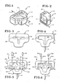
- Cuvette 10 includes a top 14, and a bottom 15 including a base 16 and a closed wall 18 formed integrally with the base and extending upwardly therefrom.
- the top 14 is generally planar and as may be best een in FIG. 3 is generally T-shaped in plan and is provided with an access slot 20 extending therethrough and also generally T-shaped in plan.
- the bottom 15 and wall 18 are generally T-shaped in plan, FIG. 4, and cooperatively provide a cavity indicated by general numerical designation 22 which, as may be best seen in FIG. 4, is also of generally T-shape.
- the top and bottom are complementary in size and shape.
- the top of the closed wall 18, as may be noted from FIG. 4, is provided with a pair of upwardly extending tapered posts 24 and 26 for being received in interference engagement with a pair of inwardly extending tapered holes 28 and 30, FIG. 3, formed in the bottom of the top 14 to secure the top and bottom together.
- the lancet 12 may be secured to the cuvette bottom 15 by providing the rearward portion of the lancet with an irregular shape as shown in dashed outline in FIG. 4 and by molding the cuvette bottom 15 around the rearward portion of the lancet.
- the access slot is of a predetermined size smaller than the cavity 22 for metering a predetermined volume of a fluid of interest, such as blood, into the cavity upon a larger volume of the fluid being present at and or wiped across the access slot.
- a fluid of interest such as blood
- the cavity 22, FIGS. 2 and 4 may be filled with a medium such as the optically transparent gel body provided with a reagent test system as disclosed in United States Patent Application Serial No. 888,755, filed on July 22, 1986, entitled GLUCOSE ASSAY, Rita C. Prodell et al. inventors, and assigned to the same assignee as the present invention.
- a fluid of interest such as a body fluid of interest (e.g. blood plasma)
- the medium undergoes a change in at least one optical transmissive property, as described above, permitting optical determinations of the fluid or analyte as described above.
- the cuvette 10 of the present invention is provided with a shape and a plurality of integrally formed optical elements for causing a beam of light, such as light beam 30 from a suitable source such as photoemissive element 32, to pass through the cuvette and a medium received within the cavity 22, by total internal reflectance and to be reflected, as indicated by reflected light beam, 34, back along a line generally parallel to the line of entry of the beam of light 30 into the cuvette and in the opposite direction of the entry of the beam of light into the cuvette.
- a beam of light such as light beam 30 from a suitable source such as photoemissive element 32
- photoemissive and photodetector elements 32 and 36 to be positioned parallel and opposite the same side or portion of the cuvette thereby permitting, for example, the lancet 12 to be secured to the cuvette on the opposite side of the optical elements 32 and 36 whereby the mechanical action of the cuvette, such as body skin piercing, does not interfere with the optical function, and particularly the optical elements such as 32 and 36 which may be associated with the cuvette as described above.
- ⁇ c sin ⁇ 1 n12 where n12 is the relative index of refraction at the interface I between the internal medium M1 and the external medium M2 and is less than unity; where n12 - n1/n2, and where n1 is the index of refraction of the internal medium M1 through which the beam of light L is transmitted obliquely, and where n2 is the index of refraction of the external medium M2 towards which the beam of light is being transmitted obliquely.
- the generally T-shaped closed wall 18 includes a cross-bar portion indicated by general numerical designation 40 and a descender portion indicated by general numerical designation 42 and wherein the cross-bar portion 40 intersects the descender portion 42 at two generally right angle portions 44 and 46.
- two reflecting prisms, 48 and 50 and formed respectively, and integrally, at the right angle portions 44 and 46 of the closed wall 18.
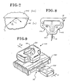
- the presence of existence of such reflecting prisms 48 and 50 may be better understood by reference to FIG. 8 wherein the portions of typical reflecting prisms of the type known to the art but missing in FIG. 5 are shown in dashed outline in FIG. 8.
- dashed outline of the reflecting prisms 48 and 50 which are redundant to the present internal reflectance, are merely removed or are not present in the embodiment of FIG. 5.
- the closed wall 18 includes a first portion 51 having parallel inner and outer surfaces 52 and 53 and a pair of opposed portions 54 and 55 having, respectively, inner surfaces 56 and 57 parallel to inner and outer surfaces 52 and 53 of the first portion 51 and, respectively, outer angular surfaces 58 and 59 disposed at a predetermined angle, e.g. approximately 45°, with respect to the parallel surfaces 52, 53, 56 and 57.
- cuvette 10, particularly closed wall 18 is provided with a shape and integrally formed reflecting prisms 48 and 50 to cause the beam of light 30 upon entry into the cuvette perpendicular to the inner and outer parallel surfaces 52 and 53 of the first portion 51 to pass through the first portion substantially without refractance, through the cavity 22 and a medium received therein, and through opposed portion 54 substantially without refractance and to internally strike the outer angular surface 58 of the opposed portion 54 at an angle ⁇ 1 above the critical angle ⁇ c (as described above) for total internal reflectance and to be reflected internally therefrom through the opposed portion 54 substantially without refractance, again through the cavity 22 and the medium contained therein and through the other opposed portion 55 substantially without refractance and to strike internally the outer angular surface 59 of the opposed portion 55 at an angle ⁇ 2 above the critical angle for total internal reflectance and to be reflected internally therefrom through the opposed portion 55, again through the cavity 22 and the medium contained
- the medium received in the cavity 22 is less dense than the optically transparent material, e.g. a suitable polymeric material, of which the closed wall 18 is made and hence the relative index of refraction between the medium and the wall material is greater than unity and thus no critical angle for reflectance is possible at this interface, however, it will be further understood that the optically transparent material of which the closed wall 18 is made is more dense than the surrounding medium, such as air, and that the relative index of refraction between the wall material of which the closed wall 18 is made and the surrounding medium is less than unity and hence a critical angle ⁇ c for total internal reflectance is present or possible.
- the optically transparent material e.g. a suitable polymeric material, of which the closed wall 18 is made and hence the relative index of refraction between the medium and the wall material is greater than unity and thus no critical angle for reflectance is possible at this interface
- the optically transparent material of which the closed wall 18 is made is more dense than the surrounding medium, such as air, and that the relative index of refraction between the wall material of
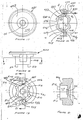
- FIG. 9 A further alternate embodiment of the present invention is illustrated in FIG. 9 and includes a cuvette 10A which, it will be understood, is of the same or substantially the same structure as the embodiments described above and illustrated in FIGS. 2, 5 and 6, except that cuvette 10A is provided with a base 16A of the size and shape shown in FIGS. 9-13.
- embodiment 10A further includes a lancet support member indicated by general numerical designation 70 having a lancet 12A received wholly therein.
- Lancet support member 70 includes a first or rearward portion 72 provided with a plurality of tapered holes 73, 74 and 75, best seen in FIGS.
- the lancet support member 70 includes an integrally formed forward portion 80 having the forward portion of the lancet 12A residing therein and wherein the forward and rearward portions of the lancet support member 70 are connected by an integrally formed intermediate portion 82 of reduced thickness to facilitate breaking of the forward portion away from the rearward portion to expose the forward portion of the lancet to puncture the skin, for example the skin of a human being, to produce a body fluid of interest.
- embodiment 10A has a spherical depression 86 formed in the top of the cuvette 10A and coextensive with the access slot 20; depression 86 facilitates wiping of a fluid of interest across the access slot 20 and entry of the fluid into and through the access slot into the cavity 22 (FIG. 10) provided internally of the cuvette 10A.
- FIGS. 14, 15 and 16 there are illustrated additional alternate embodiments of the improved cuvette of the present invention identified, respectively, by general numerical designations 100, 200, and 300; these views are similar to views 5 and 6 described above.
- Improved cuvette 100 is generally triangularly-shaped and includes a closed wall 118 also generally traingularly-shaped which, it will be understood, overlies a generally triangularly-shaped base and in cooperation therewith provides the generally triangularly shaped cavity 122 for receiving the above-described optically transparent medium including a reagent test system for reacting with a sample portion of a body fluid of interest.
- the closed wall 118 includes a transverse portion 140 for being disposed generally perpendicular to a photoemitter 132 for providing the light beam 130 and triangular wall portions 142 and 144 having formed integrally and generally intermediately thereof reflecting prisms 148 and 150, respectively.
- improved cuvette 100 passes the light beam 130 from a suitable source thereof, such as photoemitter 132, through the cuvette and the medium with test reagent system received within the cavity 122 by total internal reflectance with the internal reflectance occurring, as in embodiment 10 of FIG.
- the light beam 130 strikes wall air interface above the critical angle ⁇ 1 for total internal reflectance, is reflected internally therefrom and strikes the interface again at an angle ⁇ 2 above the critical angle whereafter the light beam is reflected, as indicated by arrow 134, back along a line generally parallel to and in the opposite direction to the direction of the line of entry of the light beam 130 into the cuvette and medium whereafter the light beam is received by the photodetector 136.
- Improved cuvette 200 functions similarly to improved cuvette 10A of FIG. 6, i.e. the material of which the optically transparent cuvette 200 is made is less dense than the medium received within the cavity 222 and thus the light beam passes through the cuvette 200 and the above-described optically transparent medium with test reagent system received within the cavity 222 by total internal reflectance, as indicated by arrows 230, 233 and 234, but with the internal reflectance occurring at the interface between the medium received within the cavity 222 and angular surfaces 161 and 162 of the closed wall 218 as shown; angular surfaces 161 and 162 are disposed generally at 45° with respect to the analytical light beam and it will be understood that angles ⁇ 1 and ⁇ 2 are above the critical angle ⁇ c for total reflectance.
- Closed wall 218 is generally rectangularly shaped and extends upwardly from a generally rectangularly shaped base and includes four wall portions 241, 242, 243 and 244 which cooperate with the base to provide cavity 222 which is generally rectangularly shaped in plan; wall 241 is for being disposed generally perpendicular to the photoemitter 232 and the photodetector 236.
- improved cuvette 300 causes the light beam 330 to pass therethrough and through the medium including a test reagent system received within the cavity 322 by total internal reflectance.
- Cuvette 300 includes a bottom generally rectangularly-shaped in plan including a base and a closed wall 318 generally rectangularly-shaped in plan extending upwardly from the base.
- Wall 318 includes four wall portions, 341, 342, 343 and 344 with the wall 341 being provided with a convex lens 346 formed integrally and intermediately thereof as shown.
- Wall 342 includes an internal surface 347 which may be provided with a suitable mirror 348 suitably secured thereto and disposed generally centrally thereof; alternatively, at least the central portion of the internal surface 347 of wall portion 342 may be suitably mirrored in the manner known to those skilled in the art.
- Wall portion 341 is for being disposed generally perpendicular to a photoemitter 332 and photodetector 336 as illustrated in FIG. 16.
- the analytical light beam 330 emanating from the photoemitter 332 passes through the convex lens 346 and is directed to the mirror 348 passing through the medium including the test reagent system received within the cavity 332 whereupon the light beam is reflected as illustrated passing again through the convex lens 346 and being directed as illustrated by arrow 334 to the photodetector 336.
- the present invention embodies both the described and shown cuvettes in combination with a lancer as well as without the lancet and that patent protection is sought for the cuvette both with and without the lancet.
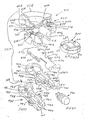
- FIGS. 17-23 there is illustrated an alternate embodiment of combination cuvette and lancet embodying the present invention and identified generally by numerical designation 410; the cuvette is indicated by general numerical designation 420 and a lancet support member is indicated by general numerical designation 460.
- Cuvette 420 (FIGS. 19, 20 and 22) provides a cavity 412 for receiving an optically transparent gel body provided with a reagent test system of the type taught above and is provided with integrally formed optical elements indicated by general numerical designations 424 and 426, which may be reflecting prisms such as reflecting prisms 48 and 50 illustrated in FIGS. 5 and 8 and described above, and further with a shape for eliminating refractance whereby a beam of light 430, as illustrated in FIG. 20 (and similar to the teachings illustrated in FIGS.
- the lancet support member 460 is provided for supporting a lancet, e.g. lancet 462 (FIGS. 22 and 23) for being advanced into engagement with the skin of a person to puncture the skin and produce the body fluid of interest, e.g. a droplet of blood.
- the lancet 462 is mounted not for advancement with the combination cuvette and lancet 410 but instead is mounted for independent advancement with respect to the cuvette whereby the cuvette and optically transparent medium contained therein may be maintained stationary and in constant optical alignment with optical analyzing structure, such as for example that included in the above-noted OPTICAL ANALYZER, at all times.
- the cuvette 420 of this embodiment is structured so as to be filled not from the top but rather from the bottom and to this end the cuvette 420 is provided with a sealing cap indicated by general numerical designation 428 (FIG. 22) for sealing the top of the cuvette cavity 412 during filling.
- a sealing cap indicated by general numerical designation 428 (FIG. 22) for sealing the top of the cuvette cavity 412 during filling.
- the bottom of the cuvette cavity 412 is closed by a top portion of the lancet support member 460, but before the lancet support member is secured to the bottom of the cuvette 420, the sealing cap 428 seals the top of the cuvette cavity 412, the cuvette 420 is inverted, and the cavity 412 is filled with the optically transparent medium such as the above-noted optically transparent gel body provided with a reagent test system.
- cuvette 420 (FIG. 22) includes a body member indicated by general numerical designation 440 in turn including a generally funnel-shaped or inverted conically shaped upper portion 442 including the above-noted bottom 437, an inwardly extending generally spherical surface 443 and a closed wall or closed wall portion 446 (particularly FIG. 18-21) formed integrally with the upper portion 442 and extending downwardly therefrom.
- the closed wall 446 includes opposed angular wall portions indicated by general numerical designations 447 and 448 (FIG. 22) providing, respectively, the above-noted optical elements 424 and 426 which, of course, are in turn formed integrally with the closed wall 446.
- Optical element 424 may be provided with a flat outer surface 451 for being disposed perpendicular to a beam of light 430 (FIG. 20), an outer angular surface 452 disposed at an angle with respect to the outer flat surface 451 to cause the beam of light 430 to internally strike the interface between the angular surface 452 and the surrounding medium (e.g. air) at an angle ⁇ 1 (FIG. 20) above the critical angle ⁇ c for total internal reflectance as taught above, and an inner flat surface 453 for being disposed perpendicular to the beam of light.
- a flat outer surface 451 for being disposed perpendicular to a beam of light 430 (FIG. 20)
- an outer angular surface 452 disposed at an angle with respect to the outer flat surface 451 to cause the beam of light 430 to internally strike the interface between the angular surface 452 and the surrounding medium (e.g. air) at an angle ⁇ 1 (FIG. 20) above the critical angle ⁇ c for total internal reflect
- optical element 426 is provided with an inner flat surface 454 for being disposed perpendicular to the beam of light, and outer angular surface 455 disposed at an angle ⁇ 2 (FIG. 20) with respect to the inner flat surface 454 to cause the beam of light 430 to internally strike the interface between the angular surface 455 and the surrounding medium (e.g. air) above the critical angle ⁇ c for total internal reflectance, and a flat outer surface 456 for being disposed perpendicular to the beam of light, e.g. arrow 434 pf FIG. 20 upon exiting the cuvette 420.
- the beam of light 430 may be provided by a suitable source such as the photoemitter 32 of FIG. 5, and may be received upon exiting the cuvette 420 by a suitable optical receiver such as the photodetector 36 of FIG. 5.
- the lancet support member 460 is for being secured to the bottom of the cuvette 420 to close the cavity 412 as noted above and for performing its function described below and includes a top member 470 and a bottom member 480.
- the bottom member 480 of the lancet support member 460 includes a resilient rearward portion 482 and a forward portion 484.
- the top member 470 of the lancet support member 460 includes a rearward portion 472 and a forward portion 474 with the top and bottom members 470 and 480 being secured together, such as for example, by upwardly extending tapered post 486 provided on the bottom member 480 which tapered post is received in interference fit with an inwardly extending tapered hole 476 formed in the upper member 470.
- top member 470 is provided with a downwardly extending tapered post, not shown, received in interference fit within tapered hole 487 provided in the bottom member 480.
- the forward portions 474 and 484 of the top and bottom members 470 and 480 provide, cooperatively, an internal chamber 488 for slidably receiving the lancet 462 with the forward tip 463 of the lancet for being extended outwardly through a surrounding opening indicated by general numerical designation 464 formed cooperatively by inwardly curved surfaces 479 and 489 formed respectively in the top and bottom members 470 and 480 of the lancet support member 460.
- general numerical designation 464 formed cooperatively by inwardly curved surfaces 479 and 489 formed respectively in the top and bottom members 470 and 480 of the lancet support member 460.
- the rearward portion 465 of the lancet 462 is secured to the resilient rearward portion 482 of the lower member 480 of the lancet support member 460, for movement therpening indicated by general numerical designation 464 formed cooperatively by inwardly curved surfaces 479 and 489 formed respectively in the top and bottom members 470 and 480 of the lancet support member 460.
- general numerical designation 464 formed cooperatively by inwardly curved surfaces 479 and 489 formed respectively in the top and bottom members 470 and 480 of the lancet support member 460.
- the rearward portion 465 of the lancet 462 is secured to th resilient rearward portion 482 of the lower member 480 of the lancet support member 460, for movement therpening indicated by general numerical designation 464 formed cooperatively by inwardly curved surfaces 479 and 489 formed respectively in the top and bottom members 470 and 480 of the lancet support member 460.
- the rearward portion 465 of the lancet 462 is secured to the resilient rearward portion 482 of the lower member 480 of the lancet support member 460, for movement therewith, by being received within an opening or slot shown in cross-section and indicated by numerical designation 481.
- the lancet 462 may be provided with a guide member 467, for example molded integrally therewith, and provided with a shape complementary to the shape of the chamber 499.
- the lower member 480 may be provided with an inwardly curved slot or groove 483.
- the tip 468 of the lancet 462 may be provided with an integrally formed, such as by molding, protective member or shroud 490, shown in FIG. 24, and which may be conveniently removed prior to use of the lancet 462 by twisting of the protective member 490 with respect to the lancet.
- the top member 470 and bottom member 480 of the lancet support member 460 will first be assembled by being secured together by the tapered posts and holes 486, 476, 487 described above. Thereafter, the lancet support member 460 is secured to the bottom of the cuvette 420 as generally described above. For such subsequent assembly, it will be noted that the bottom of the closed wall 446 of the cuvette 420 (also note FIG.
- the combination cuvette and lancet 410 may be placed in a suitable analytical device, such as the above-noted OPTICAL ANALYZER, for use.
- sealing cap 428 Referring specifically to the structure of the sealing cap 428, shown at the top portion of FIG. 22, it will be understood that the bottom surface 429 of the sealing cap 428 is complementary in shape to the top surface 443 of the upper funnel-shaped portion 442 of the cuvette 420 and that the plug member 429 of the sealing cap is complementary in shape to the tapered hole 421 formed centrally of the bottom 437 of the funnel-shaped portion 442 of the cuvette 420; sealing cap plug 429 and opening 421 are provided with a suitable interference fit.
- the sealing cap 428 will be removed, suitable force (such as from a member connected to a compression spring such as compression spring 40 shown in FIG. 2 of the above-noted United States Patent Application Serial No. 888,754 entitled OPTICAL ANALYZER) indicated by arrow 520 in FIG. 23 will be applied to the resilient rearward portion 482 of the lower member 480 of the lancet support member 460, to advance or flex the resilient rearward portion 482, as shown in FIG.
- suitable force such as from a member connected to a compression spring such as compression spring 40 shown in FIG. 2 of the above-noted United States Patent Application Serial No. 888,754 entitled OPTICAL ANALYZER
- the lancet 462 forwardly and slidably within the chamber 488 of the lower member 480 to cause the lancet tip 468 to puncture the skin of a person, for example of the finger of a person, to produce a body fluid of interest, namely a droplet of blood.
- the person may thereafter wipe the droplet of blood across the inwardly extending surface 443 of the upper funnel-shaped portion 442 of the cuvette 420, such surface serving as a depression which facilitates wiping of the droplet of blood across the opening 421 and entry of the droplet of blood into and through the opening 421 into the cavity 412 for diffusion into the optically transparent gel body contained therein.
- the optically transparent medium, e.g. gel body contained in the cavity 420 undergoes a change in at least one optical transmissive property which modifies the beam of light passing through the gel body thereby permitting the body fluid of interest, e.g. blood, to be analyzed as noted above.
- the combination cuvette and lancet 410 of the alternate embodiment shown in FIGS. 17-22 functions substantially the same as the embodiment shown in FIGS. 9-13 and described above with the beam of light 430, FIG. 20, being caused to pass through the cuvette 420, and optically transparent gel contained in the cavity 412, by total internal reflectance, as described in detail above, and to cause the beam of light to be reflected back along a line generally parallel to the direction of the line of entry of the beam of light into the cuvette and in the opposite direction of the entry of the beam of light in the cuvette, as illustrated by arrows 430 and 434 of FIG. 20.
- a cavity closure member indicated by general numerical designation 600 may be provided to close the bottom of the cavity 412.
- the top portion of the cavity closure member 600 may be provided with a plurality of inwardly extending openings 610, 612, 614 and 616 which are tapered to receive in interference fit with the downwardly extending tapered posts 510, 512, 514 and 516 provided on the closed wall 446 of the cuvette 420. Further, the top of the cavity closure member 600 may be provided with upwardly extending plug portion 620 complementary in shape to the bottom of the cavity 412, and for being received therein.
- the cuvette 420 may be provided with integrally formed, such as by molding, finger guard members 640 and 650.
- Finger guard members 640 and 650 are particularly useful to facilitate handling of the cuvette 420 by an operator and are particularly useful for preventing engagement of the handling operator's fingers with the outer surfaces 451 and 452 of optical element 424 and outer surfaces 455 and 456 of optical element 426 thereby preventing smearing or smudging of these outer optical surfaces with fingerprints from the handling operator and the placement of body oil, dirt, etc. from the fingers of the handling operator on these outer surfaces of the optical elements.
Applications Claiming Priority (4)
| Application Number | Priority Date | Filing Date | Title |
|---|---|---|---|
| US88875286A | 1986-07-22 | 1986-07-22 | |
| US07/069,505 US4873993A (en) | 1986-07-22 | 1987-07-13 | Cuvette |
| US69505 | 1987-07-13 | ||
| US888752 | 1992-05-27 |
Publications (2)
| Publication Number | Publication Date |
|---|---|
| EP0254246A2 true EP0254246A2 (fr) | 1988-01-27 |
| EP0254246A3 EP0254246A3 (fr) | 1989-08-09 |
Family
ID=26750152
Family Applications (1)
| Application Number | Title | Priority Date | Filing Date |
|---|---|---|---|
| EP87110447A Withdrawn EP0254246A3 (fr) | 1986-07-22 | 1987-07-18 | Cuvette |
Country Status (2)
| Country | Link |
|---|---|
| US (1) | US4873993A (fr) |
| EP (1) | EP0254246A3 (fr) |
Cited By (31)
| Publication number | Priority date | Publication date | Assignee | Title |
|---|---|---|---|---|
| EP0421175A1 (fr) * | 1989-10-02 | 1991-04-10 | F. Hoffmann-La Roche Ag | Tube capillaire pour prélever des échantillons de sang, son procédé de fabrication et dispositif pour mesurer le temps de coagulation |
| US5070884A (en) * | 1989-03-14 | 1991-12-10 | Eastman Kodak Company | Needle device for safely collecting blood or injecting drugs |
| GB2248944A (en) * | 1990-09-28 | 1992-04-22 | Bruker Analytische Messtechnik | Converging lens sample holder having concave and convex surfaces |
| GB2331935A (en) * | 1997-12-04 | 1999-06-09 | Hewlett Packard Co | Cartridge for sampling blood |
| EP1416263A3 (fr) * | 2002-10-29 | 2005-01-26 | Bayer Healthcare, LLC | Appareil pour l'analyse optique de petites quantités d'échantillons |
| US7892183B2 (en) | 2002-04-19 | 2011-02-22 | Pelikan Technologies, Inc. | Method and apparatus for body fluid sampling and analyte sensing |
| US7988645B2 (en) | 2001-06-12 | 2011-08-02 | Pelikan Technologies, Inc. | Self optimizing lancing device with adaptation means to temporal variations in cutaneous properties |
| US8062231B2 (en) | 2002-04-19 | 2011-11-22 | Pelikan Technologies, Inc. | Method and apparatus for penetrating tissue |
| US8079960B2 (en) | 2002-04-19 | 2011-12-20 | Pelikan Technologies, Inc. | Methods and apparatus for lancet actuation |
| US8162853B2 (en) | 2001-06-12 | 2012-04-24 | Pelikan Technologies, Inc. | Tissue penetration device |
| US8197421B2 (en) | 2002-04-19 | 2012-06-12 | Pelikan Technologies, Inc. | Method and apparatus for penetrating tissue |
| US8197423B2 (en) | 2002-04-19 | 2012-06-12 | Pelikan Technologies, Inc. | Method and apparatus for penetrating tissue |
| US8251921B2 (en) | 2003-06-06 | 2012-08-28 | Sanofi-Aventis Deutschland Gmbh | Method and apparatus for body fluid sampling and analyte sensing |
| US8262614B2 (en) | 2003-05-30 | 2012-09-11 | Pelikan Technologies, Inc. | Method and apparatus for fluid injection |
| US8296918B2 (en) | 2003-12-31 | 2012-10-30 | Sanofi-Aventis Deutschland Gmbh | Method of manufacturing a fluid sampling device with improved analyte detecting member configuration |
| US8333710B2 (en) | 2002-04-19 | 2012-12-18 | Sanofi-Aventis Deutschland Gmbh | Tissue penetration device |
| US8360992B2 (en) | 2002-04-19 | 2013-01-29 | Sanofi-Aventis Deutschland Gmbh | Method and apparatus for penetrating tissue |
| US8377381B2 (en) | 2003-01-21 | 2013-02-19 | Bayer Healthcare Llc | Optical format |
| US8439872B2 (en) | 1998-03-30 | 2013-05-14 | Sanofi-Aventis Deutschland Gmbh | Apparatus and method for penetration with shaft having a sensor for sensing penetration depth |
| US8574895B2 (en) | 2002-12-30 | 2013-11-05 | Sanofi-Aventis Deutschland Gmbh | Method and apparatus using optical techniques to measure analyte levels |
| US9072842B2 (en) | 2002-04-19 | 2015-07-07 | Sanofi-Aventis Deutschland Gmbh | Method and apparatus for penetrating tissue |
| US9089294B2 (en) | 2002-04-19 | 2015-07-28 | Sanofi-Aventis Deutschland Gmbh | Analyte measurement device with a single shot actuator |
| US9248267B2 (en) | 2002-04-19 | 2016-02-02 | Sanofi-Aventis Deustchland Gmbh | Tissue penetration device |
| US9261476B2 (en) | 2004-05-20 | 2016-02-16 | Sanofi Sa | Printable hydrogel for biosensors |
| US9427532B2 (en) | 2001-06-12 | 2016-08-30 | Sanofi-Aventis Deutschland Gmbh | Tissue penetration device |
| US9560993B2 (en) | 2001-11-21 | 2017-02-07 | Sanofi-Aventis Deutschland Gmbh | Blood testing apparatus having a rotatable cartridge with multiple lancing elements and testing means |
| US9561000B2 (en) | 2003-12-31 | 2017-02-07 | Sanofi-Aventis Deutschland Gmbh | Method and apparatus for improving fluidic flow and sample capture |
| US9795747B2 (en) | 2010-06-02 | 2017-10-24 | Sanofi-Aventis Deutschland Gmbh | Methods and apparatus for lancet actuation |
| US9820684B2 (en) | 2004-06-03 | 2017-11-21 | Sanofi-Aventis Deutschland Gmbh | Method and apparatus for a fluid sampling device |
| US9839386B2 (en) | 2002-04-19 | 2017-12-12 | Sanofi-Aventis Deustschland Gmbh | Body fluid sampling device with capacitive sensor |
| US10034628B2 (en) | 2003-06-11 | 2018-07-31 | Sanofi-Aventis Deutschland Gmbh | Low pain penetrating member |
Families Citing this family (126)
| Publication number | Priority date | Publication date | Assignee | Title |
|---|---|---|---|---|
| US5564419A (en) * | 1987-11-25 | 1996-10-15 | Radiometer A/S | Method of photometric in vitro determination of the content of oxygen in a blood sample |
| DK163194C (da) * | 1988-12-22 | 1992-06-22 | Radiometer As | Fremgangsmaade ved fotometrisk in vitro bestemmelse af en blodgasparameter i en blodproeve |
| AU635314B2 (en) * | 1989-09-08 | 1993-03-18 | Terumo Kabushiki Kaisha | Measuring apparatus |
| US5371020A (en) * | 1991-09-19 | 1994-12-06 | Radiometer A/S | Method of photometric in vitro determination of the content of an analyte in a sample |
| US5582184A (en) * | 1993-10-13 | 1996-12-10 | Integ Incorporated | Interstitial fluid collection and constituent measurement |
| US5504011A (en) * | 1994-10-21 | 1996-04-02 | International Technidyne Corporation | Portable test apparatus and associated method of performing a blood coagulation test |
| US6614522B1 (en) * | 1995-09-08 | 2003-09-02 | Integ, Inc. | Body fluid sampler |
| US5879367A (en) | 1995-09-08 | 1999-03-09 | Integ, Inc. | Enhanced interstitial fluid collection |
| US6624882B2 (en) * | 1995-09-08 | 2003-09-23 | Integ, Inc. | Methods of sampling body fluid |
| US5682233A (en) * | 1995-09-08 | 1997-10-28 | Integ, Inc. | Interstitial fluid sampler |
| AU7015096A (en) * | 1995-09-08 | 1997-04-09 | Integ, Inc. | Body fluid sampler |
| US6015392A (en) * | 1996-05-17 | 2000-01-18 | Mercury Diagnostics, Inc. | Apparatus for sampling body fluid |
| US20020010406A1 (en) | 1996-05-17 | 2002-01-24 | Douglas Joel S. | Methods and apparatus for expressing body fluid from an incision |
| EP1579814A3 (fr) | 1996-05-17 | 2006-06-14 | Roche Diagnostics Operations, Inc. | Procedes et appareil de prelevement et d'analyse de liquide organique |
| US5951492A (en) * | 1996-05-17 | 1999-09-14 | Mercury Diagnostics, Inc. | Methods and apparatus for sampling and analyzing body fluid |
| US7235056B2 (en) | 1996-05-17 | 2007-06-26 | Amira Medical | Body fluid sampling device and methods of use |
| US5879311A (en) * | 1996-05-17 | 1999-03-09 | Mercury Diagnostics, Inc. | Body fluid sampling device and methods of use |
| ES2121565B1 (es) | 1996-05-17 | 2000-12-16 | Mercury Diagnostics Inc | Elemento desechable para uso en un dispositivo de toma de muestras de fluidos corporales. |
| US6332871B1 (en) | 1996-05-17 | 2001-12-25 | Amira Medical | Blood and interstitial fluid sampling device |
| US7666150B2 (en) | 1996-05-17 | 2010-02-23 | Roche Diagnostics Operations, Inc. | Blood and interstitial fluid sampling device |
| US5857983A (en) * | 1996-05-17 | 1999-01-12 | Mercury Diagnostics, Inc. | Methods and apparatus for sampling body fluid |
| US5951493A (en) * | 1997-05-16 | 1999-09-14 | Mercury Diagnostics, Inc. | Methods and apparatus for expressing body fluid from an incision |
| US7828749B2 (en) | 1996-05-17 | 2010-11-09 | Roche Diagnostics Operations, Inc. | Blood and interstitial fluid sampling device |
| US5948695A (en) * | 1997-06-17 | 1999-09-07 | Mercury Diagnostics, Inc. | Device for determination of an analyte in a body fluid |
| US5964718A (en) * | 1997-11-21 | 1999-10-12 | Mercury Diagnostics, Inc. | Body fluid sampling device |
| US6706000B2 (en) | 1997-11-21 | 2004-03-16 | Amira Medical | Methods and apparatus for expressing body fluid from an incision |
| US6036924A (en) | 1997-12-04 | 2000-03-14 | Hewlett-Packard Company | Cassette of lancet cartridges for sampling blood |
| JP2001527216A (ja) | 1997-12-19 | 2001-12-25 | アミラ メディカル | エンボス加工されたテストストリップシステム |
| US6368563B1 (en) * | 1999-03-12 | 2002-04-09 | Integ, Inc. | Collection well for body fluid tester |
| GB0030929D0 (en) * | 2000-12-19 | 2001-01-31 | Inverness Medical Ltd | Analyte measurement |
| US7691071B2 (en) * | 2001-01-19 | 2010-04-06 | Panasonic Corporation | Lancet-integrated sensor, measurer for lancet-integrated sensor, and cartridge |
| US20020160520A1 (en) * | 2001-03-16 | 2002-10-31 | Phoenix Bioscience | Silicon nano-collection analytic device |
| US7310543B2 (en) * | 2001-03-26 | 2007-12-18 | Kumetrix, Inc. | Silicon microprobe with integrated biosensor |
| US6783502B2 (en) | 2001-04-26 | 2004-08-31 | Phoenix Bioscience | Integrated lancing and analytic device |
| US6731437B2 (en) * | 2001-05-04 | 2004-05-04 | Applera Corporation | Energy beam guide for an electrophoresis system |
| US20020188223A1 (en) * | 2001-06-08 | 2002-12-12 | Edward Perez | Devices and methods for the expression of bodily fluids from an incision |
| EP1406537B1 (fr) | 2001-06-12 | 2011-01-12 | Pelikan Technologies Inc. | Systeme integre de prelevement et d'analyse d'echantillons sanguins avec module de prelevement a utilisation multiple |
| EP1404234B1 (fr) | 2001-06-12 | 2011-02-09 | Pelikan Technologies Inc. | Dispositif permettant d'ameliorer le rendement du prelevement de sang capillaire au bout du doigt |
| US9226699B2 (en) | 2002-04-19 | 2016-01-05 | Sanofi-Aventis Deutschland Gmbh | Body fluid sampling module with a continuous compression tissue interface surface |
| US7981056B2 (en) | 2002-04-19 | 2011-07-19 | Pelikan Technologies, Inc. | Methods and apparatus for lancet actuation |
| DE60238119D1 (de) | 2001-06-12 | 2010-12-09 | Pelikan Technologies Inc | Elektrisches betätigungselement für eine lanzette |
| JP4272051B2 (ja) | 2001-06-12 | 2009-06-03 | ペリカン テクノロジーズ インコーポレイテッド | 血液試料採取装置及び方法 |
| WO2002100254A2 (fr) | 2001-06-12 | 2002-12-19 | Pelikan Technologies, Inc. | Procede et appareil pour un dispositif de lancement de lancette integre sur une cartouche de prelevement de sang |
| DE10134650B4 (de) | 2001-07-20 | 2009-12-03 | Roche Diagnostics Gmbh | System zur Entnahme kleiner Körperflüssigkeitsmengen |
| US6678542B2 (en) * | 2001-08-16 | 2004-01-13 | Optiscan Biomedical Corp. | Calibrator configured for use with noninvasive analyte-concentration monitor and employing traditional measurements |
| CA2458208A1 (fr) | 2001-08-29 | 2003-03-13 | F. Hoffmann-La Roche Ag | Procedes et structures a meche destines a etre utilises dans l'echantillonnage de fluides biologiques |
| FR2829286B1 (fr) * | 2001-09-03 | 2008-04-04 | Ge Med Sys Global Tech Co Llc | Dispositif et procede d'emission de rayons x |
| US20040229347A1 (en) * | 2001-09-17 | 2004-11-18 | Perez Edward P. | Embossed test strip system |
| JP4320255B2 (ja) | 2001-09-26 | 2009-08-26 | エフ ホフマン−ラ ロッシュ アクチェン ゲゼルシャフト | 体液を採取するための携帯型器具 |
| US7344894B2 (en) | 2001-10-16 | 2008-03-18 | Agilent Technologies, Inc. | Thermal regulation of fluidic samples within a diagnostic cartridge |
| US7050157B2 (en) * | 2001-11-08 | 2006-05-23 | Optiscan Biomedical Corp. | Reagent-less whole-blood glucose meter |
| US6989891B2 (en) * | 2001-11-08 | 2006-01-24 | Optiscan Biomedical Corporation | Device and method for in vitro determination of analyte concentrations within body fluids |
| US7061593B2 (en) * | 2001-11-08 | 2006-06-13 | Optiscan Biomedical Corp. | Device and method for in vitro determination of analyte concentrations within body fluids |
| US7141058B2 (en) | 2002-04-19 | 2006-11-28 | Pelikan Technologies, Inc. | Method and apparatus for a body fluid sampling device using illumination |
| US7229458B2 (en) | 2002-04-19 | 2007-06-12 | Pelikan Technologies, Inc. | Method and apparatus for penetrating tissue |
| US8221334B2 (en) | 2002-04-19 | 2012-07-17 | Sanofi-Aventis Deutschland Gmbh | Method and apparatus for penetrating tissue |
| US7374544B2 (en) | 2002-04-19 | 2008-05-20 | Pelikan Technologies, Inc. | Method and apparatus for penetrating tissue |
| US7909778B2 (en) | 2002-04-19 | 2011-03-22 | Pelikan Technologies, Inc. | Method and apparatus for penetrating tissue |
| US7547287B2 (en) | 2002-04-19 | 2009-06-16 | Pelikan Technologies, Inc. | Method and apparatus for penetrating tissue |
| US7485128B2 (en) | 2002-04-19 | 2009-02-03 | Pelikan Technologies, Inc. | Method and apparatus for penetrating tissue |
| US7901362B2 (en) | 2002-04-19 | 2011-03-08 | Pelikan Technologies, Inc. | Method and apparatus for penetrating tissue |
| US7232451B2 (en) | 2002-04-19 | 2007-06-19 | Pelikan Technologies, Inc. | Method and apparatus for penetrating tissue |
| US7976476B2 (en) | 2002-04-19 | 2011-07-12 | Pelikan Technologies, Inc. | Device and method for variable speed lancet |
| US7291117B2 (en) | 2002-04-19 | 2007-11-06 | Pelikan Technologies, Inc. | Method and apparatus for penetrating tissue |
| EP1501402A4 (fr) | 2002-04-19 | 2008-07-02 | Pelikan Technologies Inc | Dispositif et procede pour utiliser une lancette a vitesse variable |
| US7524293B2 (en) | 2002-04-19 | 2009-04-28 | Pelikan Technologies, Inc. | Method and apparatus for penetrating tissue |
| US7297122B2 (en) | 2002-04-19 | 2007-11-20 | Pelikan Technologies, Inc. | Method and apparatus for penetrating tissue |
| US7491178B2 (en) | 2002-04-19 | 2009-02-17 | Pelikan Technologies, Inc. | Method and apparatus for penetrating tissue |
| US7648468B2 (en) | 2002-04-19 | 2010-01-19 | Pelikon Technologies, Inc. | Method and apparatus for penetrating tissue |
| US7244265B2 (en) | 2002-04-19 | 2007-07-17 | Pelikan Technologies, Inc. | Method and apparatus for penetrating tissue |
| US7563232B2 (en) | 2002-04-19 | 2009-07-21 | Pelikan Technologies, Inc. | Method and apparatus for penetrating tissue |
| US7331931B2 (en) | 2002-04-19 | 2008-02-19 | Pelikan Technologies, Inc. | Method and apparatus for penetrating tissue |
| US7410468B2 (en) | 2002-04-19 | 2008-08-12 | Pelikan Technologies, Inc. | Method and apparatus for penetrating tissue |
| US7717863B2 (en) | 2002-04-19 | 2010-05-18 | Pelikan Technologies, Inc. | Method and apparatus for penetrating tissue |
| US9314194B2 (en) | 2002-04-19 | 2016-04-19 | Sanofi-Aventis Deutschland Gmbh | Tissue penetration device |
| US8267870B2 (en) | 2002-04-19 | 2012-09-18 | Sanofi-Aventis Deutschland Gmbh | Method and apparatus for body fluid sampling with hybrid actuation |
| US8372016B2 (en) | 2002-04-19 | 2013-02-12 | Sanofi-Aventis Deutschland Gmbh | Method and apparatus for body fluid sampling and analyte sensing |
| US7371247B2 (en) | 2002-04-19 | 2008-05-13 | Pelikan Technologies, Inc | Method and apparatus for penetrating tissue |
| US20050049522A1 (en) * | 2002-10-30 | 2005-03-03 | Allen John J | Method of lancing skin for the extraction of blood |
| US20040127818A1 (en) * | 2002-12-27 | 2004-07-01 | Roe Steven N. | Precision depth control lancing tip |
| US7815579B2 (en) * | 2005-03-02 | 2010-10-19 | Roche Diagnostics Operations, Inc. | Dynamic integrated lancing test strip with sterility cover |
| US7211052B2 (en) | 2002-12-30 | 2007-05-01 | Roche Diagnostics Operations, Inc. | Flexible test strip lancet device |
| US7214200B2 (en) | 2002-12-30 | 2007-05-08 | Roche Diagnostics Operations, Inc. | Integrated analytical test element |
| US20040132168A1 (en) * | 2003-01-06 | 2004-07-08 | Peter Rule | Sample element for reagentless whole blood glucose meter |
| US6983177B2 (en) * | 2003-01-06 | 2006-01-03 | Optiscan Biomedical Corporation | Layered spectroscopic sample element with microporous membrane |
| US20040132167A1 (en) * | 2003-01-06 | 2004-07-08 | Peter Rule | Cartridge lance |
| US20040131088A1 (en) * | 2003-01-08 | 2004-07-08 | Adtran, Inc. | Shared T1/E1 signaling bit processor |
| US20040193072A1 (en) * | 2003-03-28 | 2004-09-30 | Allen John J. | Method of analyte measurement using integrated lance and strip |
| US20040193202A1 (en) * | 2003-03-28 | 2004-09-30 | Allen John J. | Integrated lance and strip for analyte measurement |
| US7473264B2 (en) * | 2003-03-28 | 2009-01-06 | Lifescan, Inc. | Integrated lance and strip for analyte measurement |
| EP1618389A1 (fr) * | 2003-04-15 | 2006-01-25 | Optiscan Biomedical Corporation | Qualification d'element d'echantillon |
| US20050106749A1 (en) * | 2003-04-15 | 2005-05-19 | Braig James R. | Sample element for use in material analysis |
| US20040225312A1 (en) * | 2003-05-09 | 2004-11-11 | Phoenix Bioscience | Linearly lancing integrated pivot disposable |
| WO2004112602A1 (fr) | 2003-06-13 | 2004-12-29 | Pelikan Technologies, Inc. | Procede et appareil pour dispositif d'analyse sur le lieu de soin |
| US20040258563A1 (en) | 2003-06-23 | 2004-12-23 | Applera Corporation | Caps for sample wells and microcards for biological materials |
| EP1671096A4 (fr) | 2003-09-29 | 2009-09-16 | Pelikan Technologies Inc | Procede et appareil permettant d'obtenir un dispositif de capture d'echantillons ameliore |
| EP1680014A4 (fr) | 2003-10-14 | 2009-01-21 | Pelikan Technologies Inc | Procede et appareil fournissant une interface-utilisateur variable |
| US20050187525A1 (en) * | 2004-02-19 | 2005-08-25 | Hilgers Michael E. | Devices and methods for extracting bodily fluid |
| WO2005111580A1 (fr) * | 2004-05-07 | 2005-11-24 | Optiscan Biomedical Corporation | Élément d’échantillonnage avec des capacites de reduction de bord d’entrefer |
| US9775553B2 (en) | 2004-06-03 | 2017-10-03 | Sanofi-Aventis Deutschland Gmbh | Method and apparatus for a fluid sampling device |
| US20050284757A1 (en) * | 2004-06-29 | 2005-12-29 | Allen John J | Analyte measuring system which prevents the reuse of a test strip |
| US20050284773A1 (en) * | 2004-06-29 | 2005-12-29 | Allen John J | Method of preventing reuse in an analyte measuring system |
| US20060000710A1 (en) * | 2004-06-30 | 2006-01-05 | Klaus Peter Weidenhaupt | Fluid handling methods |
| US7488298B2 (en) * | 2004-10-08 | 2009-02-10 | Roche Diagnostics Operations, Inc. | Integrated lancing test strip with capillary transfer sheet |
| US20070016078A1 (en) * | 2004-12-06 | 2007-01-18 | Hoyt Clifford C | Systems and methods for in-vivo optical imaging and measurement |
| US8652831B2 (en) | 2004-12-30 | 2014-02-18 | Sanofi-Aventis Deutschland Gmbh | Method and apparatus for analyte measurement test time |
| US20060189925A1 (en) * | 2005-02-14 | 2006-08-24 | Gable Jennifer H | Methods and apparatus for extracting and analyzing a component of a bodily fluid |
| US7935063B2 (en) * | 2005-03-02 | 2011-05-03 | Roche Diagnostics Operations, Inc. | System and method for breaking a sterility seal to engage a lancet |
| US9561001B2 (en) | 2005-10-06 | 2017-02-07 | Optiscan Biomedical Corporation | Fluid handling cassette system for body fluid analyzer |
| JP4935286B2 (ja) * | 2005-10-12 | 2012-05-23 | パナソニック株式会社 | 血液センサ |
| EP2363062B1 (fr) * | 2007-04-21 | 2017-11-22 | Roche Diabetes Care GmbH | Système analytique pour détecter une analyse dans un liquide du corps |
| EP3192876A1 (fr) * | 2007-10-10 | 2017-07-19 | Pocared Diagnostics Ltd. | Système permettant d'effectuer l'identification de bactéries dans l'urine |
| CN104251911B (zh) | 2008-02-05 | 2017-05-31 | 普凯尔德诊断技术有限公司 | 用于鉴定生物样品中细菌的系统 |
| WO2009126900A1 (fr) | 2008-04-11 | 2009-10-15 | Pelikan Technologies, Inc. | Procédé et appareil pour dispositif de détection d’analyte |
| US9375169B2 (en) | 2009-01-30 | 2016-06-28 | Sanofi-Aventis Deutschland Gmbh | Cam drive for managing disposable penetrating member actions with a single motor and motor and control system |
| US8309897B2 (en) * | 2009-02-06 | 2012-11-13 | Pocared Diagnostics Ltd. | Optical measurement arrangement |
| WO2011011462A1 (fr) | 2009-07-20 | 2011-01-27 | Optiscan Biomedical Corporation | Connecteur réglable à espace mort réduit |
| US9554742B2 (en) | 2009-07-20 | 2017-01-31 | Optiscan Biomedical Corporation | Fluid analysis system |
| US10288632B2 (en) | 2009-09-21 | 2019-05-14 | Pocared Diagnostics Ltd. | System for conducting the identification of bacteria in biological samples |
| US8965476B2 (en) | 2010-04-16 | 2015-02-24 | Sanofi-Aventis Deutschland Gmbh | Tissue penetration device |
| EP3156796A1 (fr) | 2010-06-09 | 2017-04-19 | Optiscan Biomedical Corporation | Mesure d'analytes dans un échantillon de liquide prélevé chez un patient |
| US8804114B2 (en) | 2010-11-03 | 2014-08-12 | Pocared Diagnostics Ltd. | Optical cup |
| EP2729784A4 (fr) | 2011-07-06 | 2015-05-13 | Optiscan Biomedical Corp | Cellule échantillon pour système d'analyse de fluide |
| US9862920B2 (en) | 2012-12-11 | 2018-01-09 | Pocared Diagnostics Ltd. | Optics cup with curved bottom |
| US10823662B1 (en) | 2020-02-18 | 2020-11-03 | Horiba Instruments, Incorporated | Special purpose cuvette assembly and method for optical microscopy of nanoparticle colloids |
| WO2022157004A1 (fr) * | 2021-01-22 | 2022-07-28 | Löwenstein Medical Technology S.A. | Dispositif de mesure pour analyser un flux de gaz respiratoire |
Citations (8)
| Publication number | Priority date | Publication date | Assignee | Title |
|---|---|---|---|---|
| US3358689A (en) * | 1964-06-09 | 1967-12-19 | Roehr Products Company Inc | Integral lancet and package |
| US3607097A (en) * | 1967-08-09 | 1971-09-21 | Philips Corp | Analyzer for liquid samples |
| GB1322728A (en) * | 1969-11-05 | 1973-07-11 | Smith Kline French Lab | Mixing and measuring container for spectrophotometric analyzing apparatus |
| US4254223A (en) * | 1978-04-18 | 1981-03-03 | Akzona Incorporated | Apparatus for colorimetric determination |
| WO1985004089A1 (fr) * | 1984-03-09 | 1985-09-26 | Geoffrey Charles Palmer | Appareil d'echantillonnage de fluide |
| EP0164148A1 (fr) * | 1984-05-11 | 1985-12-11 | Medscan B.V. | Unité de prélèvement sanguin |
| EP0178384A2 (fr) * | 1984-09-20 | 1986-04-23 | Becton Dickinson and Company | Lancette |
| EP0181962A1 (fr) * | 1984-11-22 | 1986-05-28 | Personal Diagnostics, Inc. | Cuvette à éléments optiques intégraux |
Family Cites Families (5)
| Publication number | Priority date | Publication date | Assignee | Title |
|---|---|---|---|---|
| US3123066A (en) * | 1964-03-03 | brumley | ||
| GB947908A (en) * | 1961-09-26 | 1964-01-29 | Flexile Metal Company Ltd | Improvements in or relating to sampling devices for medical, surgical and/or veterinary use |
| US3847482A (en) * | 1972-07-10 | 1974-11-12 | Bio Data Corp | Apparatus for detecting a change in turbidity of a solution |
| US4303336A (en) * | 1978-08-28 | 1981-12-01 | Baxter Travenol Laboratories, Inc. | Method and apparatus for making a rapid measurement of the hematocrit of blood |
| US4176451A (en) * | 1978-09-14 | 1979-12-04 | Mcmorrow John J | Blood segment processor |
-
1987
- 1987-07-13 US US07/069,505 patent/US4873993A/en not_active Expired - Fee Related
- 1987-07-18 EP EP87110447A patent/EP0254246A3/fr not_active Withdrawn
Patent Citations (8)
| Publication number | Priority date | Publication date | Assignee | Title |
|---|---|---|---|---|
| US3358689A (en) * | 1964-06-09 | 1967-12-19 | Roehr Products Company Inc | Integral lancet and package |
| US3607097A (en) * | 1967-08-09 | 1971-09-21 | Philips Corp | Analyzer for liquid samples |
| GB1322728A (en) * | 1969-11-05 | 1973-07-11 | Smith Kline French Lab | Mixing and measuring container for spectrophotometric analyzing apparatus |
| US4254223A (en) * | 1978-04-18 | 1981-03-03 | Akzona Incorporated | Apparatus for colorimetric determination |
| WO1985004089A1 (fr) * | 1984-03-09 | 1985-09-26 | Geoffrey Charles Palmer | Appareil d'echantillonnage de fluide |
| EP0164148A1 (fr) * | 1984-05-11 | 1985-12-11 | Medscan B.V. | Unité de prélèvement sanguin |
| EP0178384A2 (fr) * | 1984-09-20 | 1986-04-23 | Becton Dickinson and Company | Lancette |
| EP0181962A1 (fr) * | 1984-11-22 | 1986-05-28 | Personal Diagnostics, Inc. | Cuvette à éléments optiques intégraux |
Cited By (67)
| Publication number | Priority date | Publication date | Assignee | Title |
|---|---|---|---|---|
| US5070884A (en) * | 1989-03-14 | 1991-12-10 | Eastman Kodak Company | Needle device for safely collecting blood or injecting drugs |
| US5193552A (en) * | 1989-03-14 | 1993-03-16 | Eastman Kodak Company | Needle device for safely collecting blood or injecting drugs |
| EP0421175A1 (fr) * | 1989-10-02 | 1991-04-10 | F. Hoffmann-La Roche Ag | Tube capillaire pour prélever des échantillons de sang, son procédé de fabrication et dispositif pour mesurer le temps de coagulation |
| GB2248944A (en) * | 1990-09-28 | 1992-04-22 | Bruker Analytische Messtechnik | Converging lens sample holder having concave and convex surfaces |
| US5171995A (en) * | 1990-09-28 | 1992-12-15 | Bruker Analytische Mebtechnik Gmbh | Sample holder for optical spectrometer and method for taking a spectrum |
| GB2248944B (en) * | 1990-09-28 | 1994-07-13 | Bruker Analytische Messtechnik | Converging lens sample holder for optical spectrometer and method for taking a spectrum |
| GB2331935A (en) * | 1997-12-04 | 1999-06-09 | Hewlett Packard Co | Cartridge for sampling blood |
| US6071294A (en) * | 1997-12-04 | 2000-06-06 | Agilent Technologies, Inc. | Lancet cartridge for sampling blood |
| DE19855458C2 (de) * | 1997-12-04 | 2002-01-10 | Agilent Technologies Inc | Lanzettenkassette zur Blutprobennahme |
| GB2331935B (en) * | 1997-12-04 | 2002-10-09 | Hewlett Packard Co | Lancet cartridge for sampling blood |
| US8439872B2 (en) | 1998-03-30 | 2013-05-14 | Sanofi-Aventis Deutschland Gmbh | Apparatus and method for penetration with shaft having a sensor for sensing penetration depth |
| US9694144B2 (en) | 2001-06-12 | 2017-07-04 | Sanofi-Aventis Deutschland Gmbh | Sampling module device and method |
| US8622930B2 (en) | 2001-06-12 | 2014-01-07 | Sanofi-Aventis Deutschland Gmbh | Tissue penetration device |
| US8343075B2 (en) | 2001-06-12 | 2013-01-01 | Sanofi-Aventis Deutschland Gmbh | Tissue penetration device |
| US7988645B2 (en) | 2001-06-12 | 2011-08-02 | Pelikan Technologies, Inc. | Self optimizing lancing device with adaptation means to temporal variations in cutaneous properties |
| US9427532B2 (en) | 2001-06-12 | 2016-08-30 | Sanofi-Aventis Deutschland Gmbh | Tissue penetration device |
| US9802007B2 (en) | 2001-06-12 | 2017-10-31 | Sanofi-Aventis Deutschland Gmbh | Methods and apparatus for lancet actuation |
| US8679033B2 (en) | 2001-06-12 | 2014-03-25 | Sanofi-Aventis Deutschland Gmbh | Tissue penetration device |
| US8337421B2 (en) | 2001-06-12 | 2012-12-25 | Sanofi-Aventis Deutschland Gmbh | Tissue penetration device |
| US8162853B2 (en) | 2001-06-12 | 2012-04-24 | Pelikan Technologies, Inc. | Tissue penetration device |
| US9937298B2 (en) | 2001-06-12 | 2018-04-10 | Sanofi-Aventis Deutschland Gmbh | Tissue penetration device |
| US8360991B2 (en) | 2001-06-12 | 2013-01-29 | Sanofi-Aventis Deutschland Gmbh | Tissue penetration device |
| US8206319B2 (en) | 2001-06-12 | 2012-06-26 | Sanofi-Aventis Deutschland Gmbh | Tissue penetration device |
| US8206317B2 (en) | 2001-06-12 | 2012-06-26 | Sanofi-Aventis Deutschland Gmbh | Tissue penetration device |
| US8211037B2 (en) | 2001-06-12 | 2012-07-03 | Pelikan Technologies, Inc. | Tissue penetration device |
| US9560993B2 (en) | 2001-11-21 | 2017-02-07 | Sanofi-Aventis Deutschland Gmbh | Blood testing apparatus having a rotatable cartridge with multiple lancing elements and testing means |
| US8079960B2 (en) | 2002-04-19 | 2011-12-20 | Pelikan Technologies, Inc. | Methods and apparatus for lancet actuation |
| US9072842B2 (en) | 2002-04-19 | 2015-07-07 | Sanofi-Aventis Deutschland Gmbh | Method and apparatus for penetrating tissue |
| US8333710B2 (en) | 2002-04-19 | 2012-12-18 | Sanofi-Aventis Deutschland Gmbh | Tissue penetration device |
| US9907502B2 (en) | 2002-04-19 | 2018-03-06 | Sanofi-Aventis Deutschland Gmbh | Method and apparatus for penetrating tissue |
| US8337419B2 (en) | 2002-04-19 | 2012-12-25 | Sanofi-Aventis Deutschland Gmbh | Tissue penetration device |
| US9839386B2 (en) | 2002-04-19 | 2017-12-12 | Sanofi-Aventis Deustschland Gmbh | Body fluid sampling device with capacitive sensor |
| US8360992B2 (en) | 2002-04-19 | 2013-01-29 | Sanofi-Aventis Deutschland Gmbh | Method and apparatus for penetrating tissue |
| US8197423B2 (en) | 2002-04-19 | 2012-06-12 | Pelikan Technologies, Inc. | Method and apparatus for penetrating tissue |
| US8366637B2 (en) | 2002-04-19 | 2013-02-05 | Sanofi-Aventis Deutschland Gmbh | Method and apparatus for penetrating tissue |
| US9795334B2 (en) | 2002-04-19 | 2017-10-24 | Sanofi-Aventis Deutschland Gmbh | Method and apparatus for penetrating tissue |
| US8388551B2 (en) | 2002-04-19 | 2013-03-05 | Sanofi-Aventis Deutschland Gmbh | Method and apparatus for multi-use body fluid sampling device with sterility barrier release |
| US8414503B2 (en) | 2002-04-19 | 2013-04-09 | Sanofi-Aventis Deutschland Gmbh | Methods and apparatus for lancet actuation |
| US8430828B2 (en) | 2002-04-19 | 2013-04-30 | Sanofi-Aventis Deutschland Gmbh | Method and apparatus for a multi-use body fluid sampling device with sterility barrier release |
| US8197421B2 (en) | 2002-04-19 | 2012-06-12 | Pelikan Technologies, Inc. | Method and apparatus for penetrating tissue |
| US8562545B2 (en) | 2002-04-19 | 2013-10-22 | Sanofi-Aventis Deutschland Gmbh | Tissue penetration device |
| US8574168B2 (en) | 2002-04-19 | 2013-11-05 | Sanofi-Aventis Deutschland Gmbh | Method and apparatus for a multi-use body fluid sampling device with analyte sensing |
| US9724021B2 (en) | 2002-04-19 | 2017-08-08 | Sanofi-Aventis Deutschland Gmbh | Method and apparatus for penetrating tissue |
| US8157748B2 (en) | 2002-04-19 | 2012-04-17 | Pelikan Technologies, Inc. | Methods and apparatus for lancet actuation |
| US8636673B2 (en) | 2002-04-19 | 2014-01-28 | Sanofi-Aventis Deutschland Gmbh | Tissue penetration device |
| US7892183B2 (en) | 2002-04-19 | 2011-02-22 | Pelikan Technologies, Inc. | Method and apparatus for body fluid sampling and analyte sensing |
| US9498160B2 (en) | 2002-04-19 | 2016-11-22 | Sanofi-Aventis Deutschland Gmbh | Method for penetrating tissue |
| US8062231B2 (en) | 2002-04-19 | 2011-11-22 | Pelikan Technologies, Inc. | Method and apparatus for penetrating tissue |
| US9089678B2 (en) | 2002-04-19 | 2015-07-28 | Sanofi-Aventis Deutschland Gmbh | Method and apparatus for penetrating tissue |
| US9089294B2 (en) | 2002-04-19 | 2015-07-28 | Sanofi-Aventis Deutschland Gmbh | Analyte measurement device with a single shot actuator |
| US9186468B2 (en) | 2002-04-19 | 2015-11-17 | Sanofi-Aventis Deutschland Gmbh | Method and apparatus for penetrating tissue |
| US9248267B2 (en) | 2002-04-19 | 2016-02-02 | Sanofi-Aventis Deustchland Gmbh | Tissue penetration device |
| US7820107B2 (en) | 2002-10-29 | 2010-10-26 | Bayer Healthcare Llc | Optical reagents format for small sample volumes |
| US7964412B2 (en) | 2002-10-29 | 2011-06-21 | Bayer Healthcare Llc | Optical reagent format for small sample volumes |
| US8097466B2 (en) | 2002-10-29 | 2012-01-17 | Bayer Healthcare Llc | Optical reagent format for small sample volumes |
| EP1416263A3 (fr) * | 2002-10-29 | 2005-01-26 | Bayer Healthcare, LLC | Appareil pour l'analyse optique de petites quantités d'échantillons |
| US9034639B2 (en) | 2002-12-30 | 2015-05-19 | Sanofi-Aventis Deutschland Gmbh | Method and apparatus using optical techniques to measure analyte levels |
| US8574895B2 (en) | 2002-12-30 | 2013-11-05 | Sanofi-Aventis Deutschland Gmbh | Method and apparatus using optical techniques to measure analyte levels |
| US8377381B2 (en) | 2003-01-21 | 2013-02-19 | Bayer Healthcare Llc | Optical format |
| US8262614B2 (en) | 2003-05-30 | 2012-09-11 | Pelikan Technologies, Inc. | Method and apparatus for fluid injection |
| US8251921B2 (en) | 2003-06-06 | 2012-08-28 | Sanofi-Aventis Deutschland Gmbh | Method and apparatus for body fluid sampling and analyte sensing |
| US10034628B2 (en) | 2003-06-11 | 2018-07-31 | Sanofi-Aventis Deutschland Gmbh | Low pain penetrating member |
| US9561000B2 (en) | 2003-12-31 | 2017-02-07 | Sanofi-Aventis Deutschland Gmbh | Method and apparatus for improving fluidic flow and sample capture |
| US8296918B2 (en) | 2003-12-31 | 2012-10-30 | Sanofi-Aventis Deutschland Gmbh | Method of manufacturing a fluid sampling device with improved analyte detecting member configuration |
| US9261476B2 (en) | 2004-05-20 | 2016-02-16 | Sanofi Sa | Printable hydrogel for biosensors |
| US9820684B2 (en) | 2004-06-03 | 2017-11-21 | Sanofi-Aventis Deutschland Gmbh | Method and apparatus for a fluid sampling device |
| US9795747B2 (en) | 2010-06-02 | 2017-10-24 | Sanofi-Aventis Deutschland Gmbh | Methods and apparatus for lancet actuation |
Also Published As
| Publication number | Publication date |
|---|---|
| EP0254246A3 (fr) | 1989-08-09 |
| US4873993A (en) | 1989-10-17 |
Similar Documents
| Publication | Publication Date | Title |
|---|---|---|
| EP0254246A2 (fr) | Cuvette | |
| US6365109B1 (en) | Reagentless analysis of biological samples | |
| EP1207780B1 (fr) | Dispositif de verification de haute precision d'un analyseur spectral | |
| KR100562178B1 (ko) | 중공형 절두체 시약 테스트 디바이스 | |
| US5652149A (en) | Mixing apparatus & method for an optical agglutination assay device | |
| KR19980018609A (ko) | 중공형 프러스텀을 사용한 분석물 농도 측정방법 | |
| EP0746754A1 (fr) | Recipient pour appareil d'essai automatise | |
| KR19980018608A (ko) | 원격-투약 분석물 농도 측정기 | |
| US20020110496A1 (en) | Sample tab | |
| WO1996033399A1 (fr) | Microcuvette capillaire | |
| JPH063442B2 (ja) | 液体中の化合物を分光測光法により測定するためのキユベツト | |
| EP0774657A2 (fr) | Appareil et procédé pour la détection d'un liquide | |
| PL207204B1 (pl) | Aparat do analiz zawierający kasetę do analiz, jego zastosowanie, kaseta do analiz, urządzenie do analiz | |
| JP4044163B2 (ja) | 液体検知方法および器具 | |
| WO1988001376A1 (fr) | Procede et dispositif permettant de determiner le niveau d'un analyte dans un echantillon de sang total | |
| US4753531A (en) | Flat container type analytical instrument | |
| US20190224667A1 (en) | Disposable cartridge system for point-of-care testing | |
| KR20190067777A (ko) | 당화혈색소 비율의 측정 방법 | |
| JPH0536364U (ja) | 検体容器 | |
| EP0120715A2 (fr) | Cellules de mesure optique | |
| JPS6063446A (ja) | 流体分析装置 | |
| AU606937B2 (en) | Assay apparatus and use thereof | |
| KR20190049765A (ko) | 당화혈색소 측정용 분리형 카세트 | |
| US20090247841A1 (en) | Lancet with capillary channel | |
| EP1416263A2 (fr) | Appareil pour l'analyse optique de petites quantités d'échantillons |
Legal Events
| Date | Code | Title | Description |
|---|---|---|---|
| PUAI | Public reference made under article 153(3) epc to a published international application that has entered the european phase |
Free format text: ORIGINAL CODE: 0009012 |
|
| AK | Designated contracting states |
Kind code of ref document: A2 Designated state(s): CH DE FR GB IT LI NL SE |
|
| PUAL | Search report despatched |
Free format text: ORIGINAL CODE: 0009013 |
|
| AK | Designated contracting states |
Kind code of ref document: A3 Designated state(s): CH DE FR GB IT LI NL SE |
|
| STAA | Information on the status of an ep patent application or granted ep patent |
Free format text: STATUS: THE APPLICATION IS DEEMED TO BE WITHDRAWN |
|
| 18D | Application deemed to be withdrawn |
Effective date: 19900210 |
|
| RIN1 | Information on inventor provided before grant (corrected) |
Inventor name: PALMIERI, THOMAS Inventor name: MESEROL, PETER M. |